Verilog 入门
Verilog 入门
本内容来自 牛客网Verilog入门特别版
1、一个没有输入和一个输出常数1的输出的电路,输出信号为one
module top_module(one);
    output wire one;
    assign one = 1`b1;
endmodule
2、创建一个具有一个输入和一个输出的模块,其行为类似于电路上的连线。输入信号in0,输出信号out1
module wire0(in0,out1);
    input wire in0;
    output wire out1;
    assign out1 = in0;
endmodule
3、创建一个具有 2个输入和 3个输出的模块,使用线连接的方式:
a -> z
b -> x
b -> y
input wire a b ,output wire x y z
module top_module(a,b,x,y,z);
    input wire a,b;
    output wire x,y,z;
    assign a = z;
    assign b = x;
    assign c = y;
endmodule
4、输出输入信号的值的相反的值,输入in,输出out
module top_module(
   	input in,
	output out
);
// assign out = !in;
assign out = ~in;
endmodule
5、创建实现 AND 门的模块,输入有三个wire,将三个信号(a b c)进行与操作,请思考在实际电路需要几个与门?请写出对应的RTL
输入:a、b、c
输出:d
module top_module(
    input a,
    input b,
    input c,
    output d
);
assign d = a & b & c;
endmodule
6、创建实现 OR和NOR 的模块,NOR 门是输出反相的 OR 门。
c 是 nor输出,d是or输出
输入:a、b
输出:c、d
module top_module(
    input a,
    input b,
    output c,
    output d
);
assign c = ~(a | b);
assign d = a | b;
endmodule
7、创建一个实现 XOR 门的模块
输入:a、b
输出:c
module top_module(
    input a,
    input b,
    output c
);
assign c = a ^ b;
endmodule
8、写出如图的rtl逻辑,限制使用最多四次assign
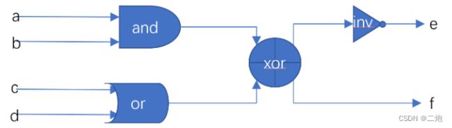
输入:a、b、c、d
输出:e、f
module top_module (
	input a,
	input b,
	input c,
	input d,
	output e,
	output f
);
// assign e = ~((a & b) ^ (c | d));
// assign f = (a & b) ^ (c | d);
xor(f,a&b,c|d);
assign e = ~f;
endmodule
9、下图为某芯片的逻辑,请通过RTL实现它的功能
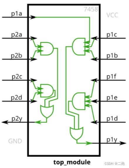
输入:p1a,,p1b,p1c,p1d,p1e,p1f,p2a,p2b,p2c,p2d
输出:p1y,p2y
module top_module (
    input p1a, p1b, p1c, p1d, p1e, p1f,
    output p1y,
    input p2a, p2b, p2c, p2d,
    output p2y
);
// assign p1y = ((p1a & p1b & p1c) | (p1d & p1e & p1f));
// assign p2y = ((p2a & p2b) | (p2c & p2d));
or (p1y, p1c & p1b & p1a, p1f & p1e & p1d);
or (p2y, p2a & p2b, p2c & p2d);
endmodule
10、根据下述逻辑,给出对应的module设计
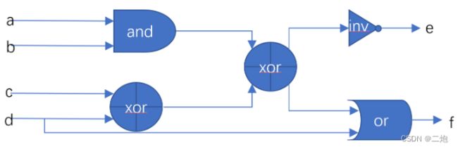
输入:a,b,c,d
输出:e,f
module top_module (
	input a,
	input b,
	input c,
	input d,
	output e,
	output f
);
assign e = ! ((a & b) ^ (c ^ d));
assign f = ((a & b) ^ (c ^ d) | d);
endmodule
11、构建一个具有一个3位输入in的信号[2:0],将其分成三个独立的输出a b c(从2到0)
输入:in
输出:a,b,c
module top_module(
    input [2:0] in,
    output a,b,c
);
assign a = in[2];
assign a = in[1];
assign a = in[0];
// 拼接字符
// assign {a,b,c} = in;
endmodule
12、一个16位信号in包含四个四位数[3:0]a [3:0]b [3:0]c [3:0]d,将它们顺序倒置为dcba输出
输入:in
输出:out
module top_module(
    input [15:0]in,
    output [15:0]out
);

wire [3:0] a,b,c,d;
assign {a,b,c,d} = in;
assign out = {d,c,b,a};

// genvar i;
// for (i=0; i<4; i=i+1) begin
//     assign out[15 - i*4 +: 4] = in[i*4 +: 4];
// end

endmodule
13、现有一个模块,输入信号为[2:0]a和[2:0]b,请输出信号的按位或[2:0]c和或信号d
输入:[2:0]a,[2:0]b
输出:[2:0]c,d
// 与:	& 按位与;	&& 逻辑与;
// 或:	| 按位或;	|| 逻辑或;
// 非:	~ 按位非;	! 逻辑非;
// 异或:^ 按位异或
module top_module(
	input [2:0] a,
	input [2:0] b,
	output [2:0] c,
	output d
);
	assign c = a | b;
	assign d = a || b;
endmodule
14、将一个五输入的信号分别进行的每一位进行: 全部按位与;全部按位或;全部按位异或
输入:[4:0]in
输出:out_and、out_or,、out_xor
module top_module(
    input [4:0] in,
    output out_and,
    output out_or,
    output out_xor
);
    assign out_and = & in[4:0];
    assign out_or = | in[4:0];
    assign out_xor = ^ in[4:0];
    // &in[4:0] 等同于
    // in[4]&in[3]&in[2]&in[1]&in[0]  |和^同理
endmodule
15、将6个输入信号串联转为四个信号输出,输入信号为[4:0]a [4:0]b [4:0]c [4:0]d [4:0]e [4:0]f,末尾增加一个宽度为两位的3,形成32位长度后,按照从前到后的顺序输出[7:0]w [7:0]x [7:0]y [7:0]z
输入:[4:0]a、[4:0]b、[4:0]c、[4:0]d、[4:0]e、[4:0]f
输出:[7:0]w、[7:0]x、[7:0]y、[7:0]z
module top_module(
    input [4:0] a, b, c, d, e, f,
    output [7:0] w, x, y, z );

    assign {w,x,y,z} = {a,b,c,d,e,f,2'd3};
endmodule
16、输入一个16位的信号in,将其从低位到高位输出(即反转顺序输出)为out
输入:[15:0] in
输出:[15:0] out
// 第一种reg + always语句
module top_module(
    input [15:0] in,
	output reg [15:0] out
);
    integer i;
    always @(*) begin
        for(i=0; i<16; i++) begin
            out[i] <= in[15-i];
        end
    end
endmodule

// 第二种generate for 内嵌的assign语句
// module top_module(
//     input [15:0] in,
// 	   output [15:0] out
// );
//     genvar i;
//     generate
//         for(i=0; i<16; i=i+1) begin
//             assign out[i] = in[15-i];
//         end
//     endgenerate
// endmodule

// 疑问:
// generate for 语句内嵌的assign语句是每次循环都赋值例化一次吗?
// 这样相当于把wire类型的assign语句变量值保存下来了,最后统一输出。
// 用reg + always语句,每次循环reg值是保存的,区别是在这里吗?
17、给定四个无符号数字,找到最大值。不使用if进行判断,尽量少使用语句的情况下完成。
输入:[7:0]a b c d
输出:[7:0] max
module top_module(
    input [7:0] a, b, c, d,
    output [7:0] max
);
    wire [7:0] max_ab;
    wire [7:0] max_ab_c;

    assign max_ab = a>b ? a : b;
    assign max_ab_c = max_ab>c ? max_ab : c;
    assign max = max_ab_c>d ? max_ab_c : d;
endmodule
18、给定五个1bit信号(a、b、c、d 和 e),生成两种25位的数据: 一种是将信号复制五次后连接起来aaaaabbbbb…,一种是将信号连接起来复制五次成为abcdeabcde… 。比较两个25位信号,如果两个信号的同样位置的位相等,则输出1。
输入:a、b、c、d、e
输出:[24:0] out
module top_module(
    input a, b, c, d, e,
	output [24:0] out
);
    wire  [24:0]  out1, out2;

    assign out1 = {{5{a}},{5{b}},{5{c}},{5{d}},{5{e}}};
    assign out2 = {5{a,b,c,d,e}};

    assign out = ~(out1 ^ out2);
endmodule
19、输入5个4bit信号,根据sel的值选出对应的信号,对应关系为:0~a 1~b 2~c 3~d 4~e 其他~置零
输入:
[3:0] a b c d e
[2:0]sel
输出:
[3:0] out
module top_module(
    input [3:0] a, b, c, d, e,
    input [2:0] sel,
    output reg [3:0] out
);
    always @(*) begin
        case (sel)
            0:  out = a;
            1:  out = b;
            2:  out = c;
            3:  out = d;
            4:  out = e;
            default:    out = 4'h0;
        endcase
    end
endmodule
20、输入一个256位信号,根据sel信号输出对应位数值,当 sel = 0 时选择 in[0],sel = 1 时选择 in[1],以此类推
输入:
[255:0] in
[7:0]sel
输出:
out
module top_module (
	input [255:0] in,
	input [7:0] sel,
	output reg out
);
	// 用此方法时,out的reg要去掉
	// assign out = in[sel];

	integer i;
    always @(*) begin
		for(i=0; i<256; i++) begin
			case(sel)
				i:	out = in[i];
			endcase
		end
    end
endmodule