Improving the Timeliness of Bluetooth Low Energy in Noisy RF Environments
2. Connection-based BLE Communication 、
、
Compared to the simpler connection-less communication mode making use of 3 advertisement channels (37, 38, and 39) to broadcast short data packets, connection-based BLE provides bidirectional data transfer between a slave and a master. After an initial setup phase using connection-less primitives, connection-based communication takes place during connection events (N0 ... Ni), as shown in Fig. 1.与利用3个广告信道(37,38和39)广播短数据分组的更简单的无连接通信模式相比,基于连接的BLE在从设备和主设备之间提供双向数据传输。在使用无连接原语的初始设置阶段之后,在连接事件(N0 ... Ni)期间发生基于连接的通信,如图1所示。
The time between the start of two consecutive connection events is defined by the connection interval (conn int). During a single connection event, master and slave exchange link-layer packets that may carry application data (yellow). In case no data needs to be sent, master and slave simply exchange link-layer keep-alive packets (dark blue), which only carry the mandatory link-layer header.两个连续连接事件开始之间的时间由连接间隔(conn int)定义。在单个连接事件期间,主交换机和从交换机交换可以携带应用数据的链路层分组(黄色)。在不需要发送数据的情况下,主设备和从设备简单地交换链路层保持活动分组(深蓝色),其仅携带强制链路层报头。
The duration of a connection event depends on the number and the size of exchanged link-layer packets and is limited by the maximum connection event length (tCE). Every connection event starts with a transmission from the master, to which the slave responds. Master and slave keep exchanging link-layer data packets until they have all been successfully sent or until tCE is reached. The last link-layer packet during a connection event is always sent from the slave to the master, after which both devices turn off their radio and resume communication at the next connection event.
连接事件的持续时间取决于交换的链路层数据包的数量和大小,并受最大连接事件长度(tCE)的限制。每个连接事件都从主设备的传输开始,从设备响应。主设备和从设备保持交换链路层数据包,直到它们全部成功发送或到达tCE为止。连接事件期间的最后一个链路层数据包始终从从设备发送到主设备,之后两个设备关闭其无线电并在下一个连接事件时恢复通信。
Using connection-based BLE, the link layer automatically handles the acknowledgment (ACK) of packets and linklayer flow control using a 1-bit ACK field and a 1-bit sequence number in the header of every link-layer packet (both keep-alive and data packets). In case a link-layer packet is not successfully received, it is automatically re-transmitted without any notification to the BLE application.使用基于连接的BLE,链路层使用1比特ACK字段和每个链路层分组的报头中的1比特序列号自动处理分组的确认(ACK)和链路层流控制(均为保持活动状态) 和数据包)。 如果没有成功接收到链路层分组,则在没有任何通知的情况下自动重新发送它到BLE应用程序。
Data channel selection. At the beginning of every connection event, one out of 37 possible BLE data channels is selected by the adaptive frequency hopping (AFH) algorithm. A new channel is chosen for every connection event and is used by master and slave to transmit/receive all packets until the end of the connection event. All 37 possible BLE data channels (0 to 36) are located in the unlicensed 2.4 GHz ISM band. The latter, however, is also used by other wireless communication technologies, such as Wi-Fi, Classic Bluetooth, and IEEE 802.15.4, that may interfere with ongoing BLE communications, leading to link-layer packet loss and re-transmissions. The AFH algorithm may choose only a subset of the 37 data channels, defined by the channel map (Cmap) set by the BLE master during connection setup.
数据通道选择。 在每个连接事件开始时,通过自适应跳频(AFH)算法选择37个可能的BLE数据信道中的一个。 为每个连接事件选择一个新信道,并由主设备和从设备用于发送/接收所有数据包,直到连接事件结束。 所有37个可能的BLE数据信道(0到36)都位于未经许可的2.4 GHz ISM频段。 然而,后者也被其他无线通信技术使用,例如Wi-Fi,经典蓝牙和IEEE 802.15.4,其可能干扰正在进行的BLE通信,导致链路层分组丢失和重传。 AFH算法可以仅选择37个数据信道的子集,由BLE主设备在连接建立期间设置的信道映射(Cmap)定义。
To mitigate the effect of co-located wireless applications or multi-path fading, the AFH algorithm may blacklist any BLE data channel with poor link quality by updating the C map of the BLE connection at runtime. A data channel disabled in the C map will not be used for communication, but may be whitelisted again. Both black- and whitelisting of BLE data channels is performed using standardized BLE commands and may only be initiated by a BLE master.
为了减轻共址无线应用或多径衰落的影响,AFH算法可以通过在运行时更新BLE连接的C映射来将任何具有较差链路质量的BLE数据信道列入黑名单。 C映射中禁用的数据通道不会用于通信,但可能会再次列入白名单。 BLE数据通道的黑名单和白名单都是使用标准化的BLE命令执行的,并且只能由BLE主机启动。
The BLE specification [4] defines a mandatory delay of at least six connection events between a slave receiving the C map, and the latter being used for actual communication. A slave is required to use the updated channel map, but cannot impose nor suggest changes in Cmap to the master in a standardized way. This can lead to long transmission delays in case a source of interference is located near the slave and is not detected by the master, as we show in Sect. 3.
BLE规范[4]定义了接收C映射的从设备之间至少六个连接事件的强制延迟,后者用于实际通信。 从站需要使用更新的通道映射,但不能以标准化方式强制或建议C映射到主站的更改。 如果干扰源位于从站附近并且主站没有检测到,这可能导致长传输延迟,如我们在Sect 3中所示。
Transmission latency. Several models capturing the transmission latency of application data sent over a BLE connection exist [8, 12, 17, 23]. However, only the model proposed by Spoerk et al. [23] uses information that is typically available from a BLE radio and can hence be directly used by an application to adapt its connection parameters at runtime. According to this model [23], the upper bound on transmission latency of application data sent over a BLE connection on an ideal channel can be computed as:
传输延迟。 捕获通过BLE连接发送的应用数据的传输延迟的几个模型存在[8,12,17,23]。 但是,只有Spoerk等人提出的模型。 [23]使用通常可从BLE无线电获得的信息,因此可由应用程序直接使用,以在运行时调整其连接参数。 根据该模型[23],在理想信道上通过BLE连接发送的应用数据的传输延迟的上限可以计算为:

where D is the data length in bytes, F is the maximum number of bytes that may be transmitted during a single connection event, conn int is the length of the connection interval, and tCE is the maximum length of a connection event [23]. 其中D是以字节为单位的数据长度,F是单个连接事件期间可以传输的最大字节数,conn int是连接间隔的长度,tCE是连接事件的最大长度[23]。
As we show in Sect. 3, an application cannot rely on this model to compute an upper bound on its end-to-end latency in noisy environments. Radio interference, indeed, causes several link-layer re-transmissions that introduce delays up to four times higher than the ones predicted by this model.
正如我们在Sect 3中所示。 应用程序不能依赖此模型来计算在嘈杂环境中其端到端延迟的上限。 实际上,无线电干扰导致若干链路层重传,其引入的延迟比该模型预测的延迟高四倍。
3 BLE Latency in Noisy RF Environments
To demonstrate the impact of radio interference on a BLE connection, we experimentally show that RF noise in a common office environment leads to high transmission latencies over BLE connections (Sect. 3.1). We use a testbed with 9 BLE nodes (Sect. 3.2) to measure the latency of individual data packets in detail and investigate how BLE’s AFH algorithm adapts the data channel map over time (Sect. 3.3). Based on our results, we highlight the specific scenarios in which the AFH algorithm is unable to cope with the surrounding interference, leading to long delays (Sect. 3.4).
为了证明无线电干扰对BLE连接的影响,我们通过实验证明,在普通办公环境中的RF噪声会导致BLE连接上的高传输延迟(第3.1节)。 我们使用带有9个BLE节点的测试平台(第3.2节)详细测量各个数据包的延迟,并研究BLE的AFH算法如何随时间调整数据通道图(第3.3节)。 根据我们的结果,我们强调了AFH算法无法应对周围干扰的特定情况,导致长时间延迟(第3.4节)。
The two BLE nodes can send F = 128 bytes during a single connection event and have a maximum connection event length of 10 ms. When using the model shown in Eq. 1 with conn int = 250 ms, an application would expect a maximum transmission latency tmax = 260 ms for each UDP packet. Fig. 2 shows the percentage of data packets that exceed this upper bound on transmission latency over the 48 hours. Each bar refers to 15 minutes, i.e., 900 UDP transmissions. During daytime, when the office is populated with employees, up to 21.74% of the UDP packets sent within 15 minutes experience a transmission latency higher than tmax. Several packets even experienced a latency higher than 1000 ms, i.e., four times higher than tmax. During nighttime, instead, when the office is at its quietest, only a minimal number of packets exhibit a latency above 260 ms. These results show that the RF noise present in a common office environment can have a significant impact on the transmission latency of connection-based BLE. To get a deeper understanding of the impact of different sources of radio interference on the BLE transmission delay, we investigate next the performance of BLE in a systematic way.
两个BLE节点可以在单个连接事件期间发送F = 128个字节,并且最大连接事件长度为10 ms。使用公式中所示的模型时如果使用conn int = 250 ms,则应用程序将期望每个UDP数据包的最大传输延迟t max = 260 ms。图2显示了在48小时内超过传输延迟上限的数据包的百分比。每个条指的是15分钟,即900 UDP传输。在白天,当办公室安装了员工时,在15分钟内发送的UDP数据包中高达21.74%的传输延迟高于tmax。几个分组甚至经历了高于1000ms的等待时间,即比tmax高四倍。在夜间,相反,当办公室处于最安静的状态时,只有最小数量的数据包表现出超过260毫秒的延迟。这些结果表明,普通办公环境中存在的RF噪声会对基于连接的BLE的传输延迟产生重大影响。为了更深入地了解不同无线电干扰源对BLE传输延迟的影响,我们接下来将系统地研究BLE的性能。

3.2 Experimental Setup
We perform our experiments on a testbed allowing us to control the RF noise experienced by each BLE node.
我们在测试平台上进行实验,允许我们控制每个BLE节点所经历的RF噪声。
Testbed facility. The testbed consists of nine RPi3 equally distributed over a University lab (6x10 meters) that is kept vacant during our experiments. Each RPi3 runs the Raspbian OS and is connected via USB to one BLE node (nRF52840 DK device). All RPi3 are connected via Ethernet and use NTP for time synchronization, providing us with the same notion of time across all testbed nodes. Each RPi3 is also augmented with the open-source D-Cube board [20], which allows us to accurately measure the power consumption of each nRF52840 DK device over time. 试验台设施。测试床由9个RPi3组成,均匀分布在大学实验室(6x10米),在实验期间保持空置。每个RPi3运行Raspbian OS,并通过USB连接到一个BLE节点(nRF52840 DK设备)。所有RPi3都通过以太网连接,并使用NTP进行时间同步,为我们提供了跨所有测试平台节点的相同时间概念。每个RPi3还增加了开源D-Cube板[20],这使我们能够准确测量每个nRF52840 DK器件随时间的功耗。
Generating interference. All RPi3 in the testbed are used to re-program the BLE nodes and to monitor the status of each experiment by logging data in persistent memory. We further make use of the RPi3 nodes in the testbed to generate Bluetooth and Wi-Fi interference using their on-board Broadcom bcm43438 radio chip. To generate Bluetooth interference, we configure each RPi3 to create a point-to-point Bluetooth RFCOMM connection with another RPi3, and to transmit RFCOMM packets with a length of 1000 bytes every 11.034 ms, resulting in a RFCOMM data rate of 725 kbits/s. To create Wi-Fi interference, we let each RPi3 generate IEEE 802.11 b/g/n packets of configurable length and rate on a given channel and with a transmission power of 30 mW. To this end, we use the approach followed in the EWSN 2018 dependability competition by Schuss et al. [19].产生干扰。测试平台中的所有RPi3都用于重新编程BLE节点,并通过在持久性存储器中记录数据来监控每个实验的状态。我们进一步利用测试平台中的RPi3节点,使用其板载Broadcom bcm43438无线电芯片产生蓝牙和Wi-Fi干扰。为了产生蓝牙干扰,我们将每个RPi3配置为与另一个RPi3建立点对点蓝牙RFCOMM连接,并每11.034 ms发送一个长度为1000字节的RFCOMM数据包,从而产生725 kbits / s的RFCOMM数据速率。为了创建Wi-Fi干扰,我们让每个RPi3在给定信道上生成可配置长度和速率的IEEE 802.11 b / g / n数据包,传输功率为30 mW。为此,我们使用Schuss等人在EWSN 2018可靠性竞争中采用的方法。 [19]。
BLE master. We use one of the RPi3 as BLE master for all our tests. This RPi3 uses its on-board BLE radio to scan for and connect to nearby IPv6-over-BLE slaves. When an IPv6-over-BLE connection is established, the master starts a UDP server that waits for incoming UDP packets. Every time a UDP packet is received, payload and reception time are logged locally via the serial interface of the node. BLE大师。我们使用RPi3之一作为BLE主机进行所有测试。该RPi3使用其板载BLE无线电扫描并连接到附近的IPv6-over-BLE从站。建立IPv6-over-BLE连接时,主服务器启动等待传入UDP数据包的UDP服务器。每次接收到UDP数据包时,都会通过节点的串行接口在本地记录有效负载和接收时间。
3.4 Lessons Learned
Our experiments show that BLE connections are eventually able to successfully transmit all data packets, even under heavy Wi-Fi or Bluetooth interference, hence confirming BLE’s high reliability highlighted by [22]. Although no data packet is lost, however, we have observed that the transmission latency significantly increases under interference.
我们的实验表明,即使在严重的Wi-Fi或蓝牙干扰下,BLE连接最终也能够成功传输所有数据包,从而证实了BLE的高可靠性[22]。 虽然没有数据包丢失,但我们观察到传输延迟在干扰下显着增加。
Inefficiency of AFH. In particular, our experiments highlight that, in two situations, the AFH algorithm used by BLE is unable to cope with the surrounding interference, leading to long delays. First, the AFH algorithm loses its efficacy in the presence of interference generated by other radio technologies making use of frequency hopping, such as Classic Bluetooth. Second, in the presence of Wi-Fi interference located close to the slave, the master is unable to detect the RF noise and does not update the list of blacklisted channels. In these situations, the number of re-transmissions performed by a BLE connection drastically increases, leading to high latencies that may be unacceptable for safety-critical BLE applications such as health care monitoring [3, 11]. AFH效率低下。特别是,我们的实验强调,在两种情况下,BLE使用的AFH算法无法应对周围的干扰,导致长时间的延迟。首先,AFH算法在存在由使用跳频的其他无线电技术(例如经典蓝牙)产生的干扰的情况下失去其功效。其次,如果存在靠近从站的Wi-Fi干扰,则主站无法检测到RF噪声,也无法更新列入黑名单的通道列表。在这些情况下,由BLE连接执行的重传次数急剧增加,导致高延迟,这对于安全关键的BLE应用(如医疗监控)可能是不可接受的[3,11]。
Need for runtime adaptation. In order to avoid such long latencies, delay-sensitive BLE applications need to adjust the connection parameters of their ongoing connections, e.g., by lowering the connection interval according to changes in the link-quality. However, this task is complicated by the fact that the BLE specification [4] does not provide a standardized way for an application to directly get feedback about ongoing link-layer (re-)transmissions or about the quality of a BLE connection. As a consequence, to be aware about the timeliness of its communications, a BLE application needs to pro-actively let the communicating nodes exchange application-level messages to explicitly monitor delays, e.g., by means of round-trip time estimations. Pro-actively exchanging application messages, however, is an unnecessary communication overhead and an additional energy expenditure that is undesirable for resource-constrained BLE nodes. 需要运行时调整。为了避免这种长时间延迟,延迟敏感的BLE应用需要调整其正在进行的连接的连接参数,例如,通过根据链路质量的变化降低连接间隔。然而,由于BLE规范[4]没有为应用程序提供直接获得关于正在进行的链路层(重新)传输或关于BLE连接质量的反馈的标准化方式,因此该任务变得复杂。因此,为了了解其通信的及时性,BLE应用需要主动让通信节点交换应用级消息以明确地监视延迟,例如通过往返时间估计。然而,主动交换应用消息是不必要的通信开销和额外的能量消耗,这对于资源受限的BLE节点是不期望的。
In the next section, we show that any application compliant to the BLE specification [4] can estimate the impact of interference on an ongoing connection by estimating the number of connection events necessary to complete a successful data transmission. We show how this quantity can be measured without any extra communication overhead or energy cost using the timing information of HCI commands.在下一节中,我们将展示符合BLE规范[4]的任何应用程序都可以通过估计完成成功数据传输所需的连接事件数来估计干扰对正在进行的连接的影响。我们展示了如何使用HCI命令的定时信息在没有任何额外通信开销或能量成本的情况下测量该数量。
4 Measuring and Modeling BLE Latency
In this section, we first revise the model shown in Eq. 1 in order to capture the nCE, i.e., the number of connection events necessary to complete a successful data transmission (Sect. 4.1). After discussing the unavailability of linklayer information on standard-compliant BLE host devices (Sect. 4.2), we show how a BLE application can estimate nCE autonomously in two ways. First, we show how to relate nCE to the round-trip time measured by introducing applicationlayer ACKs (Sect. 4.3). As this method is inaccurate and increases the communication overhead as well as the energy expenditure of BLE devices, we propose a second way to estimate nCE that makes use of the timing information of commands sent over the standardized host controller interface between host processor and BLE controller (Sect. 4.4).
在本节中,我们首先修改公式中所示的模型。 为了捕获nCE,即完成成功数据传输所需的连接事件的数量(第4.1节)。 在讨论了符合标准的BLE主机设备上的链路层信息不可用之后(第4.2节),我们展示了BLE应用如何以两种方式自主地估计nCE。 首先,我们展示如何将nCE与通过引入应用层ACK确定的往返时间联系起来(第4.3节)。 由于这种方法不准确并且增加了通信开销以及BLE设备的能量消耗,我们提出了第二种估算nCE的方法,该方法利用通过主机处理器和BLE控制器之间的标准化主机控制器接口发送的命令的定时信息。 (第4.4节)。
4.1 Revising the BLE Timeliness Model
We start by revising the timeliness model from [23] shown in Eq. 1. The latter describes how an application data packet of length D (bytes) is split into data fragments with a maximum size F (bytes), each of which is transmitted on a separate connection event. As discussed in [23], the model neglects the effects of link-layer packet loss on the transmission delay of the individual fragments. 我们首先修改方程式[23]中的时效性模型。 后者描述了长度为D(字节)的应用数据包如何被分成具有最大大小F(字节)的数据片段,每个数据片段在单独的连接事件上发送。 如[23]中所讨论的,该模型忽略了链路层分组丢失对各个分段的传输延迟的影响。
To model the effects of link-layer packet loss and retransmissions, we introduce the nCE metric, which expresses the number of connection events necessary to successfully transmit individual data fragments, into the model as:为了模拟链路层丢包和重传的影响,我们引入了nCE度量,它表示成功传输单个数据片段所需的连接事件的数量,如下所示:

where dD=Fe captures the fragmentation of data with length D into one or multiple data fragments of length F, and nCE f is the nCE of a single data fragment f .其中dD = Fe将具有长度D的数据碎片捕获到一个或多个长度为F的数据片段中,并且nCE f是单个数据片段f的nCE。
By knowing the nCE of each fragment, Eq. 2 now captures the impact of RF noise on the quality of a BLE connection, and is hence able to provide an upper bound on transmission delay. This, however, requires a precise nCE measurement.通过了解每个片段的nCE,Eq。 图2现在捕获RF噪声对BLE连接质量的影响,因此能够提供传输延迟的上限。 然而,这需要精确的nCE测量。
4.2 Challenges in Measuring nCE
The main challenge in measuring nCE on a standardcompliant host device is the nature of the BLE communication stack. The latter is split into two separate parts, a BLE controller and a BLE host [4], that exchange commands via a standardized Host Controller Interface (HCI) (see Fig. 6). To simplify the development of BLE applications, the controller implements the physical and link layer – practically acting as a black box to the host running the application. 在标准兼容主机设备上测量nCE的主要挑战是BLE通信栈的性质。后者分为两个独立的部分,一个BLE控制器和一个BLE主机[4],它们通过标准化的主机控制器接口(HCI)交换命令(见图6)。为了简化BLE应用程序的开发,控制器实现了物理层和链路层 - 实际上充当运行应用程序的主机的黑盒子。
The controller, indeed, provides all services needed for connection-based BLE communication, such as autonomous link-layer retransmissions and acknowledgments, timing of connection events, and data channel selection (including blacklisting) using the AFH algorithm. Controllers are often separate chips that are closed-source and cannot be accessed or modified by developers. The only way for a host to interact with a controller is to provide high-level parameters and listen for HCI events. No info about the BLE connection, such as the number of retransmissions, is passed to the host.实际上,控制器使用AFH算法提供基于连接的BLE通信所需的所有服务,例如自主链路层重传和确认,连接事件的定时以及数据信道选择(包括黑名单)。控制器通常是独立的芯片,它们是闭源的,开发人员无法访问或修改。主机与控制器交互的唯一方法是提供高级参数并监听HCI事件。没有关于BLE连接的信息(例如重传次数)被传递给主机。
The BLE host implements the upper communication layers of the BLE stack, including the L2CAP layer, the ATT/- GATT protocols, and support for IPv6 communication.
BLE主机实现BLE堆栈的上层通信层,包括L2CAP层,ATT / - GATT协议以及对IPv6通信的支持。
Due to the nature of the BLE stack, several challenges arise when measuring nCE on a host, which we discuss next. Packet transmission. The controller autonomously handles the scheduling of transmissions and the ACK of packets in its transmission buffer. The host can use HCI commands to add a new data packet to the transmission buffer of the controller, but has no implicit control over its timing and no information about when it has actually been sent. The host hence assumes that each packet will be sent, eventually, as long as the underlying BLE connection is not dropped.由于BLE堆栈的性质,在主机上测量nCE时会出现一些挑战,我们将在下面讨论。分组传输。控制器在其传输缓冲器中自主地处理传输的调度和分组的ACK。主机可以使用HCI命令将新数据包添加到控制器的传输缓冲区,但是没有对其时序的隐式控制,也没有关于何时实际发送的信息。因此,主机假设每个数据包最终都会被发送,只要基础BLE连接不被丢弃即可。
Due to these challenges, directly measuring the nCE of an ongoing connection from the BLE host is not possible. A host may, however, estimate the nCE using application-layer acknowledgments or HCI information, as we show next.由于这些挑战,无法直接测量来自BLE主机的持续连接的nC、E。 但是,主机可以使用应用层确认或HCI信息来估计nCE,如下所示。
Packet transmission. The controller autonomously handles the scheduling of transmissions and the ACK of packets inits transmission buffer. The host can use HCI commands to add a new data packet to the transmission buffer of the controller, but has no implicit control over its timing and no information about when it has actually been sent. The host hence assumes that each packet will be sent, eventually, as long as the underlying BLE connection is not dropped. 分组传输。控制器自主地处理传输的调度和传输缓冲器中的分组的ACK。主机可以使用HCI命令将新数据包添加到控制器的传输缓冲区,但是没有对其时序的隐式控制,也没有关于何时实际发送的信息。因此,主机假设每个数据包最终都会被发送,只要基础BLE连接不被丢弃即可。
Buffer management. The controller implements its own management of both reception and transmission buffer. The BLE host (and hence the application developer) has no direct control over the controller’s buffers and can only request the number and length of available buffers in the controller.缓冲管理。控制器实现自己对接收和传输缓冲区的管理。 BLE主机(以及应用程序开发人员)无法直接控制控制器的缓冲区,只能请求控制器中可用缓冲区的数量和长度。
Channel selection. At connection setup, the link layer of the BLE master provides the data channel map to the slave. During an active connection, the controller of both slave and master autonomously handles BLE data channel selection. The BLE host, however, has no control or info over the data channel used in current or upcoming connection events. 频道选择。在连接建立时,BLE主站的链路层将数据通道映射提供给从站。在有效连接期间,从设备和主设备的控制器自主地处理BLE数据信道选择。但是,BLE主机无法控制或信息当前或即将发生的连接事件中使用的数据通道。
Channel selection. At connection setup, the link layer of the BLE master provides the data channel map to the slave. During an active connection, the controller of both slave and master autonomously handles BLE data channel selection. The BLE host, however, has no control or info over the data channel used in current or upcoming connection events.
链接质量信息。 BLE规范[4]不提供任何标准化原语,允许主机检索关于正在进行的连接的链路质量信息。关于BLE数据信道上的接收信号强度(RSS),信噪比(SNR)或重传次数的任何信息都限于BLE控制器的链路层。因此,BLE主机无法以标准化方式检索任何这些低级测量。
Due to these challenges, directly measuring the nCE of an ongoing connection from the BLE host is not possible. A host may, however, estimate the nCE using application-layer acknowledgments or HCI information, as we show next.
由于这些挑战,无法直接测量来自BLE主机的持续连接的nCE。但是,主机可以使用应用层确认或HCI信息来估计nCE,如下所示。
4.3 Estimating nCE using Round-Trip Time
An application can estimate the number of connection events necessary to successfully transmit individual data fragments by using application-layer ACKs and by measuring the round-trip time (tRTT ): we refer to this form of nCE estimation as RTT-based nCE. When carrying out an RTT-based nCE estimation, every data transmission initiated by an application (master or slave) is confirmed by an ACK from the other party’s application, as shown in Fig. 7. 应用程序可以通过使用应用层ACK并通过测量往返时间(tRTT)来估计成功传输单个数据片段所需的连接事件的数量:我们将这种形式的nCE估计称为基于RTT的nCE。 当执行基于RTT的nCE估计时,由应用(主或从)发起的每个数据传输由来自另一方的应用的ACK确认,如图7所示。
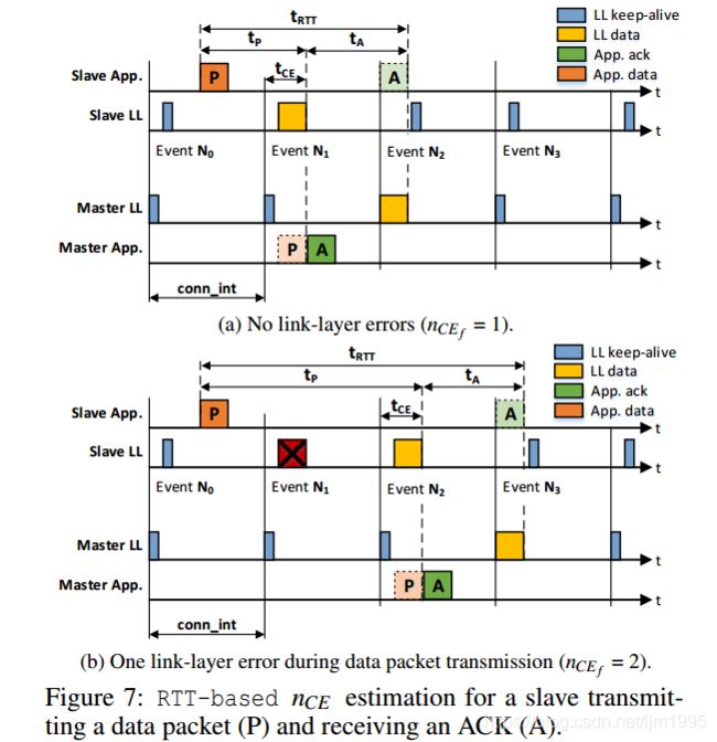
An application measures tRTT as the time between the instant in which it adds a data packet P to the transmission buffer of the controller, and the time in which it receives the application-layer ACK A in its reception buffer. The measured tRTT can be expressed as the sum of tP and tA:
应用程序测量tRTT作为其将数据分组P添加到控制器的传输缓冲器的时刻与其在其接收缓冲器中接收应用层ACK A的时间之间的时间。 测得的tRTT可以表示为tP和tA的总和:
![]()
where tP is the time it takes between P being added to the controller’s transmission buffer and being received in the other party’s reception buffer. tA, instead, captures the time between P being received into the receiving buffer, and the subsequent application-layer ACK being received by the application that originally sent P. Fig. 7 shows an example in which a slave sends a data packet consisting of a single fragment, and a master replies with an application-level ACK.
其中tP是P被添加到控制器的传输缓冲区和被接收到另一方的接收缓冲区之间所需的时间。 相反,tA捕获P被接收到接收缓冲器之间的时间,以及由最初发送P的应用程序接收的后续应用层ACK。图7示出了从设备发送由a组成的数据分组的示例。 单个片段,主服务器使用应用程序级别的ACK进行回复。
Both data exchanges (actual packet and application-layer ACK) can be modeled as individual data transmissions, each with an upper latency bound tmax that is calculated using Eq. 2. For our model, we assume that data packet and ACK have the same length D. Furthermore, because an application has no insight about the performance of each individual fragment, it can only derive a nCE f that is the same for all fragments involved in the data exchange (data packet and ACK). Following these assumptions, we calculate tRT T as:两个数据交换(实际分组和应用层ACK)可以被建模为单独的数据传输,每个数据传输具有使用等式1计算的上延迟界限t max。 2.对于我们的模型,我们假设数据包和ACK具有相同的长度D.此外,因为应用程序不了解每个单独片段的性能,所以它只能导出对于所涉及的所有片段都相同的nCE f。 在数据交换(数据包和ACK)中。 根据这些假设,我们将tRT T计算为:
![]()
By measuring tRTT , an application can hence estimate the average nCE f for all fragments in the data exchange as:通过测量tRTT,应用程序因此可以估计数据交换中所有片段的平均nCE f,如下所示:

Limitations. A basic requirement to be able to carry out RTT-based nCE estimation is that the developer has full control over the application running on both master and slave. This may not necessarily be the case, for example, when a slave acting as IPv6-over-BLE node transmits IPv6 messages to a router (master). Although a developer could force a round-trip time measurement using L2CAP ping messages, RTT-based nCE estimation might not be suitable for energy-constrained slaves. The same observation applies when introducing application-layer ACKs, as they increase communication overhead and hence cause an additional power consumption, as we show in Sect. 6.2. 限制。能够执行基于RTT的nCE估计的基本要求是开发人员可以完全控制在主设备和从设备上运行的应用程序。例如,当充当IPv6-over-BLE节点的从设备向路由器(主设备)发送IPv6消息时,情况可能不一定是这种情况。虽然开发人员可以使用L2CAP ping消息强制进行往返时间测量,但基于RTT的nCE估计可能不适合能量受限的slaves。引入应用层ACK时也会采用相同的观察,因为它们会增加通信开销,从而导致额外的功耗,正如我们在Sect6.2中所示。
Another limitation of RTT-based nCE estimation is that it assumes the same nCE f for all fragments involved in the data exchange. On the one hand, this assumes the link to be symmetric, which may lead to an underestimation of nCE f in case the data packet is retransmitted for several connection events, but the ACK is received immediately. On the other hand, by estimating an average nCE f for all fragments, RTT-based nCE estimation cannot capture the case in which interference leads to a high nCE f for specific fragments.基于RTT的nCE估计的另一个限制是它假定数据交换中涉及的所有片段具有相同的nCE f。一方面,这假设链路是对称的,这可能导致在针对若干连接事件重传数据分组的情况下低估nCE f,但是立即接收到ACK。另一方面,通过估计所有片段的平均nCE f,基于RTT的nCE估计不能捕获干扰导致特定片段的高nCE f的情况。
4.4 Estimating nCE using HCI Timing Info
In order to tackle the limitations of RTT-based nCE estimations, we present another approach that estimates the number of connection events necessary to successfully transmit a data fragment by using HCI timing information. We refer to this form of nCE estimation as HCI-based nCE estimation. As HCI commands and events are standardized, any BLE-compliant host can make use of this approach. 为了解决基于RTT的nCE估计的局限性,我们提出了另一种方法,该方法通过使用HCI定时信息来估计成功传输数据片段所需的连接事件的数量。 我们将这种形式的nCE估计称为基于HCI的nCE估计。 由于HCI命令和事件是标准化的,任何符合BLE标准的主机都可以使用这种方法。
Differently from RTT-based nCE estimation, the HCI-based approach can discern the nCE f of each individual fragment, and its computation varies for masters and slaves.与基于RTT的nCE估计不同,基于HCI的方法可以辨别每个单独片段的nCE f,并且其计算因主设备和从设备而异。
4.4.1 Estimating nCE on a BLE slave
Fig. 8 shows the inner working of HCI-based nCE estimation for a BLE slave transmitting a packet P consisting of a single data fragment to the master. Compared to Fig. 7, one can notice that the master is no longer sending applicationlayer ACKs after receiving a packet. Fig. 8 also highlights a number of time-stamps (TADD, TFREE, and TRX) that can be retrieved from the communication exchanges on the HCI. 图8示出了用于BLE从设备的基于HCI的nCE估计的内部工作,其将由单个数据片段组成的分组P发送到主设备。与图7相比,可以注意到主设备在接收到分组之后不再发送应用层ACK。图8还突出显示了可以从HCI上的通信交换机检索的多个时间戳(TADD,TFREE和TRX)。
Whenever an application needs to transmit data over the BLE connection, it uses the HCI ACL data packet command to add data to the transmission buffer of the controller. We define this instant TADD and measure it in the HCI driver of the host. We also define TFREE as the instant in which the buffer of the controller changes state and measure it by listening for HCI Number Of Completed Packets events. The latter are issued from the controller when a transmission buffer is freed, due to successful data transmission. 每当应用程序需要通过BLE连接传输数据时,它使用HCI ACL数据包命令将数据添加到控制器的传输缓冲区。我们定义这个即时TADD并在主机的HCI驱动程序中测量它。我们还将TFREE定义为控制器的缓冲区改变状态并通过侦听HCI Number of Completed Packets事件来测量它的瞬间。由于成功的数据传输,当释放传输缓冲器时,后者由控制器发出。
Both in the absence (Fig. 8a) and in the presence (Fig. 8b) of link-layer errors, the only available timing info that can be derived by the slave via the HCI is the time tTX elapsed between the data being added to the controller’s transmission buffer (TADD) and the buffer being actually freed (TFREE):
图8示出了用于BLE从设备的基于HCI的nCE估计的内部工作,其将由单个数据片段组成的分组P发送到主设备。与图7相比,可以注意到主设备在接收到分组之后不再发送应用层ACK。图8还突出显示了可以从HCI上的通信交换机检索的多个时间戳(TADD,TFREE和TRX)。
Whenever an application needs to transmit data over the BLE connection, it uses the HCI ACL data packet command to add data to the transmission buffer of the controller. We define this instant TADD and measure it in the HCI driver of the host. We also define TFREE as the instant in which the buffer of the controller changes state and measure it by listening for HCI Number Of Completed Packets events. The latter are issued from the controller when a transmission buffer is freed, due to successful data transmission. 每当应用程序需要通过BLE连接传输数据时,它使用HCI ACL数据包命令将数据添加到控制器的传输缓冲区。我们定义这个即时TADD并在主机的HCI驱动程序中测量它。我们还将TFREE定义为控制器的缓冲区改变状态并通过侦听HCI Number of Completed Packets事件来测量它的瞬间。由于成功的数据传输,当释放传输缓冲器时,后者由控制器发出。
Both in the absence (Fig. 8a) and in the presence (Fig. 8b) of link-layer errors, the only available timing info that can be derived by the slave via the HCI is the time tTX elapsed between the data being added to the controller’s transmission buffer (TADD) and the buffer being actually freed (TFREE):在没有链路层错误(图8a)和存在(图8b)的情况下,从站通过HCI可以获得的唯一可用时序信息是在添加到数据之间经过的时间tTX。控制器的传输缓冲区(TADD)和实际释放的缓冲区(TFREE):

![]()
According to Fig. 8, we can observe that tTX can be expressed as the sum of two components tF and tLL:
根据图8,我们可以观察到tTX可以表示为两个分量tF和tLL的总和:
![]()
where tF is the latency of a single data fragment (which may carry up to F bytes) into the master’s reception buffer, whereas tLL captures the time between the reception of the data fragment into the master’s reception buffer and the slave receiving the link-layer ACK and freeing the buffer (TFREE). 其中tF是单个数据片段(可能携带高达F字节)到主机接收缓冲区的延迟,而tLL捕获数据片段接收到主机接收缓冲区和从机接收链路层之间的时间 确认并释放缓冲区(TFREE)。
The latency of a single data fragment tF can be derived from Eq. 2 by setting D = F, hence deriving:
单个数据片段tF的等待时间可以从等式2中通过设置D = F到出,因此得出:
![]()
Compared to the data fragment that may have a length of up to 255 bytes according to the BLE specification [4], the link-layer acknowledgment only has a length of 16-bits. We therefore assume that the link-layer acknowledgment is successfully transmitted within the first transmission attempt and neglect its duration, resulting in tLL = conn int. With this assumption, we can calculate tTX (using Eq. 5) as:
与根据BLE规范[4]可能具有最多255个字节的长度的数据片段相比,链路层确认仅具有16比特的长度。 因此,我们假设链路层确认在第一次传输尝试中成功传输并忽略其持续时间,从而导致tLL = conn int。 有了这个假设,我们可以将tTX(使用等式5)计算为:
![]()
A BLE application using the HCI communication to measure tTX (using Eq. 7) can hence estimate the current nCE f as:因此,使用HCI通信来测量tTX(使用等式7)的BLE应用可以将当前nCE f估计为:

4.4.2 Estimating nCE on a BLE master
HCI-based nCE estimation can be used on a master device using the same approach and HCI timing information described in Sect. 4.4.1 (i.e., tT X = TFREE ? TADD). The main difference compared to HCI-based nCE estimation on a slave is that the link-layer ACK for the data fragment sent by the master comes within the same connection event, as shown in Fig. 9. Therefore, tLL is already captured by the maximum connection event length tCE value in Eq. 6. This allows us to calculate tT X as:
基于HCI的nCE估计可以使用与Sect中描述的相同方法和HCI定时信息在主设备上使用。 4.4.1(即tT X = TFREE-TADD)。 与从站上基于HCI的nCE估计相比的主要差异在于,由主站发送的数据片段的链路层ACK在同一连接事件内,如图9所示。因此,tLL已被捕获 公式中的最大连接事件长度tCE值 这允许我们将tT X计算为:
![]()
An application running on the BLE master can hence estimate the current nCE f value using the measured tT X as:因此,在BLE主站上运行的应用程序可以使用测量的tT X估计当前的nCE f值:

We describe next the implementation of RTT-based or HCI-based nCE estimation on the nRF52840 DK platform using the Zephyr operating system (OS)我们接下来描述使用Zephyr操作系统(OS)在nRF52840 DK平台上实现基于RTT或基于HCI的nCE估计。
5 Implementing nCE Estimation on BLE Hosts
In this section, we present the implementation of a BLE slave using RTT-based or HCI-based nCE estimation on the Nordic Semiconductor nRF52840 DK platform [15]. The latter embeds an ARM Cortex-M4F application processor, a nRF52840 chip with 1024 kB of flash and 256 kB of memory, as well as a radio supporting BLE communication up to version 5. Note that the same implementation can be used out-of-the-box on all nRF52 variants. 在本节中,我们将介绍在Nordic Semiconductor nRF52840 DK平台上使用基于RTT或基于HCI的nCE估计的BLE从站实现[15]。后者嵌入了一个ARM Cortex-M4F应用处理器,一个带有1024 kB闪存和256 kB存储器的nRF52840芯片,以及一个支持BLE通信的无线电,最高版本为5.注意,相同的实现可以在不使用的情况下使用。所有nRF52型号的盒子。
Since we use only standardized BLE functionality, our implementation can be ported on every hardware platform that is compliant to the BLE specifications v4.1 and above. Even devices using a proprietary communication interface between BLE host and controller such as the TI CC26xx platform can use our approaches with just minor adaptations. 由于我们仅使用标准化的BLE功能,因此我们的实现可以移植到符合BLE规范v4.1及更高版本的每个硬件平台上。即使在BLE主机和控制器(如TI CC26xx平台)之间使用专有通信接口的设备也可以使用我们的方法进行微调。
The Zephyr OS used for our implementation already includes a BLE communication stack (including IPv6-overBLE support) that is fully compliant to the BLE specification. Furthermore, the Zephyr BLE stack on the nRF52 platform uses the standardized HCI to exchange information between the BLE controller and the BLE host. 用于我们实现的Zephyr OS已经包括一个完全符合BLE规范的BLE通信栈(包括IPv6-overBLE支持)。此外,nRF52平台上的Zephyr BLE堆栈使用标准化的HCI在BLE控制器和BLE主机之间交换信息。
5.1 RTT-based nCE Estimation
We start by implementing the RTT-based nCE estimation approach in the slave application described in Sect. 3.2. For every UDP data message (with a UDP length of 29 bytes) sent by the slave, the master responds with an 8-byte long UDP acknowledgment. We measure the transmission time of every UDP message right before it is added to the transmission buffer of the controller. The reception time is measured immediately after the application was notified about the incoming application-layer acknowledgment from the master. Both timestamps measure the current system uptime in milliseconds, which we retrieve by calling k uptime get(). After every successful data transmission, the BLE application calculates the round-trip time tRTT of the recent data exchange and estimates the current nCE f value using Eq. 3.
我们首先在Sect中描述的从属应用程序中实现基于RTT的nCE估计方法。3.2。 对于从设备发送的每个UDP数据消息(UDP长度为29字节),主设备以8字节长的UDP确认进行响应。 我们在将每个UDP消息添加到控制器的传输缓冲区之前测量它们的传输时间。 在通知应用程序关于来自主设备的传入应用层确认之后立即测量接收时间。 两个时间戳都以毫秒为单位测量当前系统的正常运行时间,我们通过调用k uptime get()来检索这些时间。 在每次成功的数据传输之后,BLE应用程序计算最近数据交换的往返时间tRTT并使用等式3估计当前的nCEf值
5.2 HCI-based nCE Estimation
We next implement HCI-based nCE estimation reusing the slave application from Sect. 3.2 and adding the nCE measurements to the BLE host in the HCI driver layer (hci core). Every time the host sends a HCI ACL Data Packet command to the BLE controller in order to transmit application data, we store the current system uptime as TADD. When the BLE controller issues an HCI Number Of Completed Packets event to notify the host about the successful data transmission, we store TFREE as the current system uptime. TADD and TFREE are retrieved using k uptime get() and measured in milliseconds. 我们接下来实现基于HCI的nCE估计,重用来自Sect的从属应用程序。 3.2并将nCE测量值添加到HCI驱动程序层(hci核心)中的BLE主机。每次主机向BLE控制器发送HCI ACL数据包命令以传输应用程序数据时,我们将当前系统正常运行时间存储为TADD。当BLE控制器发出HCI Number of Completed Packets事件以通知主机成功传输数据时,我们将TFREE存储为当前系统正常运行时间。使用k uptime get()检索TADD和TFREE,并以毫秒为单位进行测量。
The nCE estimation is performed in the HCI driver layer on the host using Eq. 8 each time the controller has successfully transmitted a data fragment. To provide BLE applications with the possibility to retrieve the current nCE f when using HCI-based nCE estimation, we extend the HCI driver with the function bt hci get nce(), which returns the most recent nCE f estimate. This function is a custom addition to the BLE stack and can be added to any BLE controller driver, independently of the type of communication used between BLE host and controller (HCI or proprietary).
使用等式1在主机上的HCI驱动器层中执行nCE估计。每次控制器成功传输数据片段时,为了在使用基于HCI的nCE估计时为BLE应用程序提供检索当前nCE f的可能性,我们使用函数bt hci get nce()扩展HCI驱动程序,该函数返回最近的nCE f估计。此功能是BLE堆栈的自定义添加,可以添加到任何BLE控制器驱动程序,与BLE主机和控制器(HCI或专有)之间使用的通信类型无关。
7 Increasing the Timeliness of BLE using nCE
To increase the timeliness of BLE applications in noisy RF environments, we can use nCE information to adapt the BLE connection interval at runtime in order to mitigate the presence of interference while minimizing energy consumption (Sect. 7.1). Towards this goal, we can use a series of recent nCE f estimates to predict the nCE f of upcoming data fragment transmissions (Sect. 7.2).
为了在嘈杂的RF环境中提高BLE应用的及时性,我们可以使用nCE信息在运行时调整BLE连接间隔,以减少干扰的存在,同时最大限度地降低能耗(第7.1节)。 为实现这一目标,我们可以使用一系列最近的nCEf估计来预测即将到来的数据片段传输的nCEf(第7.2节)。
7.1 Adapting the BLE Connection at Runtime
Following Eq. 2, a delay-sensitive BLE application is able to compute the maximum connection interval allowing its communications to sustain an upper bound on the transmission delay tmax despite the presence of surrounding interference. From Eq. 2 we can indeed derive:
以下等式2所示,延迟敏感的BLE应用能够计算最大连接间隔,从而允许其通信维持传输延迟tmax的上限,尽管存在周围干扰。 来自Eq2我们确实可以得出:
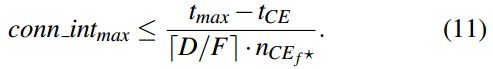
where nCEf* is the expected number of connection events necessary to successfully transmit upcoming data fragments.其中nCEf *是成功传输即将发生的数据片段所需的连接事件的预期数量。
Depending on the conn intmax computed using Eq. 11, the slave application can request a new connection interval from the master1. conn intmax represents the most energy-efficient connection interval to be used in order to sustain the upper bound on transmission delay tmax — provided that nCE f ? correctly captures the expected number of connection events necessary to successfully transmit upcoming data fragments. We discuss in the next section how an application can make use of the recent nCE f estimates to predict this value.
取决于使用Eq计算的conn intmax。 如图11所示,从应用程序可以从master1请求新的连接间隔。 conn intmax表示用于维持传输延迟t max的上限的最节能的连接间隔 - 假设nCEf* 正确捕获成功传输即将到来的数据片段所需的预期连接事件数。 我们将在下一节讨论应用程序如何利用最近的nCEf估计值来预测此值。
7.2 Predicting Future nCE f Values
Using a series of recent nCE f measurements, we can predict the expected number of connection events necessary to successfully transmit upcoming data fragments (nCEf*). This allows us to find the most efficient connection interval conn intmax and adapt the BLE connection so that future data transmissions do not exceed the maximum transmission delay tmax. To achieve this goal, we use a simple filtering approach that calculates the maximum nCE f value out of a given observation window of L fragments. Research on IEEE 802.15.4 communication has shown that such a maximum filtering approach can be used to select suitable communication parameters that minimize the number of packets exceeding an upper latency bound [13]. Using such a filtering approach, we can predict nCE f ? as:
使用一系列最近的nCE f测量,我们可以预测成功传输即将到来的数据片段所需的连接事件的预期数量(nCEf*)。 这允许我们找到最有效的连接间隔conn intmax并调整BLE连接,以便将来的数据传输不超过最大传输延迟tmax。 为了实现这一目标,我们使用一种简单的过滤方法来计算L片段的给定观察窗口中的最大nCEf值。 对IEEE 802.15.4通信的研究表明,这种最大过滤方法可用于选择合适的通信参数,以最小化超过上等延迟界限的数据包数量[13]。 使用这种过滤方法,我们可以预测nCEf* 如:
![]()
where nCE f ? is the predicted number of connection events necessary to successfully transmit upcoming data fragments, whereas nCE f (t) to nCE f (t - L) are the latest nCE f estimates obtained following the approach explained in Sect. 4. Finding an optimal L. We next experimentally investigate a suitable observation window length L. We consider six different lengths (16, 32, 64, 128, 256, and 512) and compute nCE f ? according to Eq. 12. We then instruct a BLE slave to adapt its connection interval according to Eq. 11 and experimentally measure (i) the number of delayed packets (i.e., the number of packets whose latency exceeds the expected upper bound tmax), and (ii) the energy consumption of the slave over time. We make use of the same setup described in Sect. 3.2, i.e., a slave and a master communicating using tmax = 260 ms, tCE = 10 ms, and F=128 bytes in the presence of Bluetooth and Wi-Fi interference near the slave.
其中nCEf *是成功发送即将到来的数据片段所需的连接事件的预测数量,而nCEf(t)到nCE f(t-L)是根据Sect中解释的方法获得的最新nCE f估计值。 4.寻找最佳L.我们接下来实验研究一个合适的观察窗长L.我们考虑六种不同的长度(16,32,64,128,256和512)并计算nCE f? 根据Eq。 12.然后,我们指示BLE从站根据Eq调整其连接间隔。 在图11中实验测量(i)延迟分组的数量(即,其等待时间超过预期上限tmax的分组的数量),以及(ii)从属设备随时间的能量消耗。 我们使用Sect中描述的相同设置。 3.2,即,在从设备附近存在蓝牙和Wi-Fi干扰的情况下,使用tmax = 260ms,tCE = 10ms和F = 128字节进行通信的从设备和主设备。
In principle, we expect the number of delayed packets to be high when using a short observation window. When using a short L, indeed, the limited information about the amount of interference affecting the channel in the recent past translates in an optimistic prediction (higher conn int). At the same time, we also expect that when using a longer L, at least one of the observed nCE f values captures a burst of interference and hence results in a pessimistic prediction (lower conn int). As a lower connection interval implies a higher radio activity, we expect the energy consumption to increase for longer L values.
原则上,我们期望在使用短观察窗时延迟包的数量很高。 实际上,当使用短L时,关于最近过去影响信道的干扰量的有限信息转换为乐观预测(更高的连接)。 同时,我们还期望当使用更长的L时,至少一个观察到的nCE f值捕获一个干扰突发并因此导致悲观预测(更低的conn int)。 由于较低的连接间隔意味着较高的无线电活动,我们预计能量消耗会随着较长的L值而增加。
Fig. 12 shows the results of our evaluation. As expected, the percentage of delayed packets decreases for larger observation windows, whilst the average power consumption of the system increases. To find the optimal L, we calculate the power consumption necessary to transmit a timely packet g [μW=%] for the different values of L. Fig. 12 (bottom) shows that selecting L=64 offers a good trade-off between energy-efficiency and timeliness of BLE transmissions under both Bluetooth (Fig. 12(a)) and Wi-Fi (Fig. 12(b)) interference. With this setting, only 0.6% of all data transmissions exceed the latency bound, even under Wi-Fi interference.
图12显示了我们的评估结果。 正如预期的那样,对于较大的观察窗口,延迟分组的百分比降低,而系统的平均功耗增加。 为了找到最佳L,我们计算了为L的不同值传输及时数据包g [μW=%]所需的功耗。图12(底部)显示选择L = 64提供了能量之间的良好折衷 - 蓝牙(图12(a))和Wi-Fi(图12(b))干扰下的BLE传输的效率和及时性。 使用此设置,即使在Wi-Fi干扰下,也只有0.6%的数据传输超过了延迟限制。