第4章_瑞萨MCU零基础入门系列教程之瑞萨 MCU 源码设计规范
本教程基于韦东山百问网出的 DShanMCU-RA6M5开发板 进行编写,需要的同学可以在这里获取: https://item.taobao.com/item.htm?id=728461040949
配套资料获取:https://renesas-docs.100ask.net
瑞萨MCU零基础入门系列教程汇总: https://blog.csdn.net/qq_35181236/article/details/132779862
第4章 瑞萨 MCU 源码设计规范
本章目标
- 了解 FSP 源码结构和设计规范
- 理解模块设计思路与调用方法
4.1 总体框架
4.1.1 源码层次与目录
瑞萨给开发者提供了“灵活配置软件包”(FSP,Flexible Software Package),从底往上提供了多层次的软件,如下图所示:
从下往上可以分为这几层:
- 板级支持包(BSP,Board Support Package):简单地说,从上电开始执行的第 1 条指令直到 main 函数,这个过程的代码就是 BSP 提供的。它的主要任务是确保 MCU 从复位状态切换为用户应用程序状态。在此过程中,它将设置时钟、中断、栈、堆及 C 语言运行环境。它还会配置端口的 I/O 引脚,并执行任何特定的电路板初始化。函数以"R_BSP_"开头,宏以"BSP_“开头,数据类型以”_bsp"开头。
- 硬件抽象层驱动(HAL,Hardware Abstraction Layer Drivers):简单地说,使用 BSP的代码可以让程序运行到 main 函数,但是在 main 函数里怎么去访问 GPIO、I2C、SPI 等设备,需要使用 HAL 的代码。HAL 就是对 MCU 寄存器操作的封装,通过 HAL 函数,编写程序时无需关注底层具体的硬件操作,而是把精力放在更上层的操作上,这样编写的代码也更容易移植到其他 MCU 上。函数名以"R_"开头。
- 中间件(Middleware):中间件层位于 HAL 层之上、用户应用程序之下,为应用程序提供功能栈和协议。比如想模拟一个 USB 串口时,HAL 层已经实现了 USB 的传输,而 USB 串口协议是在 USB 传输之上实现的一套机制,USB 串口协议是一套纯软件的协议,可以归为中间件。
- 实时操作系统(RTOS,Real Time Operating System):它仅仅依赖于底下的 BSP,提供多任务、同步互斥等功能。
- 应用程序(Application):在最上层,它可以使用 HAL 函数访问硬件,也可以使用中间件完成复杂的功能。
以第 1 个程序为例,工程目录如下:
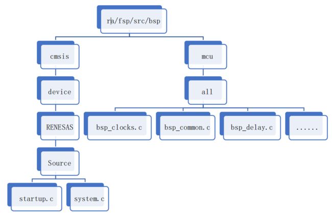
- BSP 源码:从文件名字可以知道功能为启动、系统、时钟/中断相关的操作

- HAL 源码:这个程序只涉及 GPIO 的操作,所以只有 ioport 相关的 HAL 源码
- BSP 的配置文件:这些文件是 FSP 的配置工具生成的,里面是 BSP 相关的参数

- 用户数据:比如用户在 FSP 配置界面选择使用哪些 GPIO、哪些 SPI 控制器
- 用户代码(Application):可以在 hal_entry.c 里添加自己的代码
- 链接脚本:使用 e2 studio 时,它是使用 GNU GCC 工具链来编译程序,需要链接脚本
4.1.2 调用过程示例
以工程“MyBlinkyProject”为例,在 hal_entry.c 中,操作 LED 的代码如下:
void hal_entry(void)
{
    /* TODO: add your own code here */
    extern bsp_leds_t g_bsp_leds;
    bsp_leds_t Leds = g_bsp_leds;

    while (1)
    {
        g_ioport.p_api->pinWrite(&g_ioport.p_ctrl, Leds.p_leds[BSP_LED_LED1],         			BSP_IO_LEVEL_LOW);

        R_BSP_SoftwareDelay(1, BSP_DELAY_UNITS_SECONDS);

        g_ioport.p_api->pinWrite(&g_ioport.p_ctrl, Leds.p_leds[BSP_LED_LED1],        			BSP_IO_LEVEL_HIGH);

        R_BSP_SoftwareDelay(1, BSP_DELAY_UNITS_SECONDS);
    }
#if BSP_TZ_SECURE_BUILD
    /* Enter non-secure code */
    R_BSP_NonSecureEnter();
#endif
}
- 第9行的“g_ioport.p_api->pinWrite”就是调用r_ioport.c里的“R_IOPORT_PinWrite”函数,这是 Application 对 HAL 库函数的调用。
4.2 模块设计思想
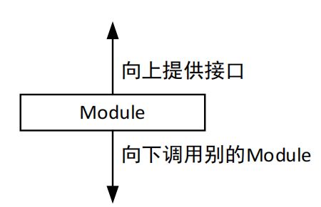
使用 FSP 编写程序时有 4 个层次:Application 是用户编写的,Middleware 是第 3 方的代码,BSP 的代码量很少,所以 HAL 层是 FSP 的核心。HAL 层是各个模块的驱动程序,这些驱动程序被称为Module,一个Module向上提供接口供人调用,向下可能要用到其他Module,如下:

怎么使用一个 Module 提供的接口呢?以工程“MyBlinkyProject”为例,有以下 2 种方法调用 r_ioport.c 提供接口:
g_ioport.p_api->pinWrite(&g_ioport.p_ctrl, Leds.p_leds[BSP_LED_LED1], BSP_IO_LEVEL_LOW);
R_IOPORT_PinWrite(&g_ioport_ctrl, Leds.p_leds[BSP_LED_LED1], BSP_IO_LEVEL_LOW);
它们有何不同?这就涉及 FSP 源码设计的理念:
- 配置与接口分离
- 接口与实例分离
4.2.1 配置与接口分离
以 GPIO 为例,如下图有 1 个 LED、1 个按键:

对于同一个 MCU,PIN1、PIN2 的操作是类似的,它们的接口函数可以只写一套。但是PIN1 需要被设置为输出功能,PIN2 需要被设置为输入功能并且使能它的内部上拉电阻。即:PIN1、PIN2 的接口函数可以是同一套,但是它们的配置是不一样的。
对于 ioport,使用 ioport_pin_cfg_t 结构体来描述一个引脚的配置:
typedef struct st_ioport_pin_cfg
{
    uint32_t pin_cfg; ///< Pin PFS configuration - Use ioport_cfg_options_t parameters
  						  to configure
    bsp_io_port_pin_t pin; ///< Pin identifier
} ioport_pin_cfg_t;
比如对于 PIN1,在 FSP 的配置工具里把它配置为输出;对于 PIN2,在 FSP 的配置工具里把它配置为输入、上拉,可以得到下面 2 项:
const ioport_pin_cfg_t g_bsp_pin_cfg_data[] ={
……
{ .pin = BSP_IO_PORT_00_PIN_05,
 .pin_cfg = ((uint32_t) IOPORT_CFG_IRQ_ENABLE
 | (uint32_t) IOPORT_CFG_PORT_DIRECTION_INPUT
 | (uint32_t) IOPORT_CFG_PULLUP_ENABLE) },
{ .pin = BSP_IO_PORT_00_PIN_06,
 .pin_cfg = ((uint32_t) IOPORT_CFG_PORT_DIRECTION_OUTPUT
 | (uint32_t) IOPORT_CFG_PORT_OUTPUT_LOW) },
……
};
使用硬件前,需要使用接口函数根据用户提供的配置信息来配置硬件。对于 ioport,使用 ioport_api_t 结构体来描述引脚的接口函数,在 r_ioport.c 里可以看到如下结构体:
/* IOPort Implementation of IOPort Driver */
const ioport_api_t g_ioport_on_ioport =
{
    .open = R_IOPORT_Open,
    .close = R_IOPORT_Close,
    .pinsCfg = R_IOPORT_PinsCfg,
    .pinCfg = R_IOPORT_PinCfg,
    .pinEventInputRead = R_IOPORT_PinEventInputRead,
    .pinEventOutputWrite = R_IOPORT_PinEventOutputWrite,
    .pinRead = R_IOPORT_PinRead,
    .pinWrite = R_IOPORT_PinWrite,
    .portDirectionSet = R_IOPORT_PortDirectionSet,
    .portEventInputRead = R_IOPORT_PortEventInputRead,
    .portEventOutputWrite = R_IOPORT_PortEventOutputWrite,
    .portRead = R_IOPORT_PortRead,
    .portWrite = R_IOPORT_PortWrite,
};
对于 ioport,配置与接口是分离的:在 ioport_cfg_t 参数里指定引脚、指定配置值,然后调用“pinCfg”函数指针去配置引脚。使用 FSP 的配置工具时,选择某个引脚、设置它的参数,就会生成对应的 ioport_cfg_t 结构体。当我们编写程序调用 r_ioport.c 里的pinCfg”函数指针时,传入这个 ioport_cfg_t 结构体。
4.2.2 接口与实例分离
假设有如下图所示的两代产品,它们的 LED 接法不一样:

对于第 1 代产品,在 r_ioport.c 里已经实现了如下结构体:
/* IOPort Implementation of IOPort Driver */
const ioport_api_t g_ioport_on_ioport =
{
     .open = R_IOPORT_Open,
     .close = R_IOPORT_Close,
     .pinsCfg = R_IOPORT_PinsCfg,
     .pinCfg = R_IOPORT_PinCfg,
     .pinEventInputRead = R_IOPORT_PinEventInputRead,
     .pinEventOutputWrite = R_IOPORT_PinEventOutputWrite,
     .pinRead = R_IOPORT_PinRead,
     .pinWrite = R_IOPORT_PinWrite,
     .portDirectionSet = R_IOPORT_PortDirectionSet,
     .portEventInputRead = R_IOPORT_PortEventInputRead,
     .portEventOutputWrite = R_IOPORT_PortEventOutputWrite,
     .portRead = R_IOPORT_PortRead,
     .portWrite = R_IOPORT_PortWrite,
};
对于第 2 代产品,我们可以在 r_spiioport.c 里实现如下结构体:
/* IOPort Implementation of SPIIOPort Driver */
const ioport_api_t g_spiioport_on_ioport =
{
     .open = R_SPIIOPORT_Open,
     .close = R_SPIIOPORT_Close,
     .pinsCfg = R_SPIIOPORT_PinsCfg,
     .pinCfg = R_SPIIOPORT_PinCfg,
     .pinEventInputRead = R_SPIIOPORT_PinEventInputRead,
     .pinEventOutputWrite = R_SPIIOPORT_PinEventOutputWrite,
     .pinRead = R_SPIIOPORT_PinRead,
     .pinWrite = R_SPIIOPORT_PinWrite,
     .portDirectionSet = R_SPIIOPORT_PortDirectionSet,
     .portEventInputRead = R_SPIIOPORT_PortEventInputRead,
     .portEventOutputWrite = R_SPIIOPORT_PortEventOutputWrite,
     .portRead = R_SPIIOPORT_PortRead,
     .portWrite = R_SPIIOPORT_PortWrite,
};
现在有两个接口结构体:g_ioport_on_ioport、g_spiioport_on_ioport,使用哪一个?在哪里指定?需要引入另一个概念:实例。以 ioport 为例,有如下结构体类型:
/** This structure encompasses everything that is needed to use an instance of this
interface.
*/
typedef struct st_ioport_instance
{
 ioport_ctrl_t * p_ctrl; ///< Pointer to the control structure for this instance
 ioport_cfg_t const * p_cfg; ///< Pointer to the configuration structure for this instance
 ioport_api_t const * p_api; ///< Pointer to the API structure for this instance
} ioport_instance_t;
ioport_instance_t 结构体中有 3 个成员:
- p_cfg 指针:使用不同的引脚、不同的配置时,就让它指向一个对应的配置结构体;
- p_api 指针:使用不同的硬件接口时,就让它指向对应的接口函数结构体;
- p_ctrl 指针:起辅助作用,比如用来标记是否启用了该模块、记录它的寄存器基地址
以工程“MyBlinkyProject”为例,在 ra_gen\common_data.c 中定义了一个实例化对象:
const ioport_instance_t g_ioport =
{ .p_api = &g_ioport_on_ioport, .p_ctrl = &g_ioport_ctrl, .p_cfg = &g_bsp_pin_cfg, };
g_ioport 里:
- p_cfg 指向 g_bsp_pin_cfg,它是配置信息;
- p_api 指向 g_ioport_on_ioport,它是接口信息;
- p_ctrl 指向 g_ioport_ctrl,它只是被用来记录驱动是否被打开。
对于第 1 代产品,g_ioport 的 p_api 指向 g_ioport_on_ioport;对于第 2 代产品,让它指向 g_spiioport_on_ioport。使用实例化结构体 g_ioport 来操作 LED 时,即使更换了底层的操作接口,用户的代码仍然无需改变:
g_ioport.p_api->pinWrite(&g_ioport.p_ctrl, Leds.p_leds[BSP_LED_LED1], BSP_IO_LEVEL_LOW);
如果直接使用接口函数操作 LED 的话,如下:
R_IOPORT_PinWrite(&g_ioport_ctrl, Leds.p_leds[BSP_LED_LED1], BSP_IO_LEVEL_LOW);
对于第 2 代产品,就需要修改成另一个接口,如下:
R_SPIIOPORT_PinWrite(&g_ioport_ctrl, Leds.p_leds[BSP_LED_LED1], BSP_IO_LEVEL_LOW);
使用实例化结构体来操作硬件,在代码的统一性、可读性和可移植性上是有很大优势的。它允许应用程序和硬件之间的进一步抽象。更改底层的外围设备时,只需要修改实例化结构体,不需要更改应用层代码。在实际开发过程中,也可以直接调用底层 API 函数(比如 R_IOPORT_PinWrite),这有两个原因:
- 基于编译器优化的考虑:假设定义了 10 个 API 接口函数,但是应用层代码只用到 1 个,那么另外的 9 个函数是可以被“优化掉”的,它们可以不被编进可执行程序里。如果使用实例化结构体的话,因为 p_api 里引用了这 10 个函数,它们都不会被优化掉。
- 一些客户可能只希望调用最底层的 API(避免过于繁琐的函数指针)。
4.3 代码规范
4.3.1 术语
- **模块(Module):**模块可以是外设驱动程序、纯软件或介于这两者之间,并且是 FSP 的构建模块。模块通常是独立的单元,但它们可能依赖于其他模块。可以通过组合多个模块来构建应用程序,为用户提供所需功能。
- 模块实例(Module Instance): 单个、独立的实例化(配置)模块。比如 r_ioport.c实现了 GPIO 的操作,它是一个 Module。要操作某个引脚时,就需要“模块实例”即“ioport_instance_t 结构体”,它里面含有配置信息、接口信息。
- 接口( Interfaces): 接口包含 API 定义,具有相似功能的模块可以共用这些 API 定义。模块通过这些定义提供常用功能。通过这些 API 定义,使用相同接口的模块可以互换使用。可以将接口视为两个模块之间的合同,两个模块均同意使用合同中达成一致的信息进行协作。接口只是定义,并不会增加代码的大小。比如在 r_ioport_api.h 里定义了 ioport 的 API。
- 实例(Instances): 接口规定所提供的功能,而实例则真正实现了这些功能。比如r_ioport.h 里定义了 API 接口,在 r_ioport.c 里实现了这些接口,r_ioport.c 就是“实例”。
- 驱动程序( Drivers): 驱动程序是一种特定类型的模块,可以直接修改 RA 产品家族MCU 上的寄存器。
- **堆叠(Stacks):**这个单词很容易跟 C 语言里的堆(heap)、栈(stack)混淆,但是在这里它不是堆栈的意思。FSP 架构所采用的设计方式是,模块可以协同工作以形成一个堆叠。堆叠就是由顶层模块及其所有依赖项组成,简单地说就是多个有依赖关系的模块。
- 应用程序(Application): 归用户所有并由用户维护的代码。
- 回调函数(Callback Functions): 当有事件发生时(例如,USB 接收到一些数据时),将调用这些函数。它们是应用程序的组成部分,如果用于中断,应尽量简短,因为它们将在中断服务程序内运行,会阻止其他中断执行。
4.3.2 API 命名规则
一般来说,内部函数遵循“NounNounVerb”(名词名词动词)的命名约定,例如CommunicationAbort()。函数的返回值表示是否成功,函数要对外输出结果时,这些结果只在输出参数中返回,并且第一个参数始终是指向其控制结构体的指针。下面是 FSP 中常用前缀:
- R_BSP_xxx: BSP 函数的前缀,例如 R_BSP_VersionGet()。
- BSP_xxx: BSP 宏的前缀,例如 BSP_IO_LEVEL_LOW。
- FSP_xxx: 常用的 FSP的前缀,主要定义错误代码(例如 FSP_ERR_INVALID_ARGUMENT)和版本信息(例如 FSP_VERSION_BUILD)。
- g_
on 实例的常量全局结构体的名称,用这个结构体管理 API 的各个实现函数,比如 g_ioport_on_ioport 结构体里是 r_ioport.c 实现的各个 API 函数。: - r_
_api.h: 接口模块头文件的名称,例如 r_spi_api.h。 - R_
_ FSP 驱动程序 API 的名称,例如 R_SPI_WriteRead()。: - RM_
_ 中间件函数的名称,例如 RM_BLE_ABS_Open()。:


