2D&3D融合
概述
截止目前为止,我们学习了机器人学,学习了2D和3D视觉算法。我们也学习了2D相机(图像数据的来源)和3D相机(点云数据的来源)工作原理。
实际上,我们最终要做的,是一个手眼机器人系统。在这个系统里,相机与机器人构成了两个非常关键的部分,它们之间需要密切配合,因此,它们之间的关系,也就非常重要。确定相机与机器人之间的关系,这是手眼标定要解决的问题。
另一方面,在很多场合,为了增强算法的鲁棒性,我们通常同时使用图像数据与点云数据,这又涉及到2D与3D配准的问题。
相机配准

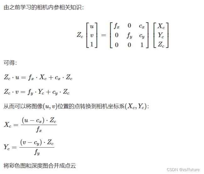
通过双重循环遍历
/**
     * 将彩色图和深度图合并成点云
     * @param matrix 相机内参矩阵3x3
     * @param rgb    彩色图
     * @param depth  深度图
     * @param cloud  输出点云
     */
static void convert(Mat &matrix, Mat &rgb, Mat &depth, PointCloud::Ptr &cloud) {
    double camera_fx = matrix.at(0, 0);
    double camera_fy = matrix.at(1, 1);
    double camera_cx = matrix.at(0, 2);
    double camera_cy = matrix.at(1, 2);

    cout << "fx: " << camera_fx << endl;
    cout << "fy: " << camera_fy << endl;
    cout << "cx: " << camera_cx << endl;
    cout << "cy: " << camera_cy << endl;

    // 遍历深度图
    for (int v = 0; v < depth.rows; v++)
        for (int u = 0; u < depth.cols; u++) {
            // 获取深度图中(m,n)处的值
            ushort d = depth.ptr(v)[u];
            // d 可能没有值,若如此,跳过此点
            if (isnan(d) && abs(d) < 0.0001)
                continue;
            // d 存在值,则向点云增加一个点
            PointT p;

            // 计算这个点的空间坐标
            p.z = double(d) / 1000; //单位是米
            p.x = (u - camera_cx) * p.z / camera_fx;
            p.y = (v - camera_cy) * p.z / camera_fy;

            // 从rgb图像中获取它的颜色
            // rgb是三通道的BGR格式图,所以按下面的顺序获取颜色
            Vec3b bgr = rgb.at(v, u);
            p.b = bgr[0];
            p.g = bgr[1];
            p.r = bgr[2];

            // 把p加入到点云中
            cloud->points.push_back(p);
            //cout << cloud->points.size() << endl;
        }


    // 设置并保存点云
    cloud->height = 1;
    cloud->width = cloud->points.size();
    cout << "point cloud size = " << cloud->points.size() << endl;
    cloud->is_dense = false;
}
int main(){
    cv::Mat cameraMatrix; // 从文件加载相机内参
    cv::Mat rgb;         // 从相机得到RGB彩色图
    cv::Mat depth;       // 从相机得到depth深度图
    PointCloud::Ptr pCloud = PointCloud::Ptr(new PointCloud);
    convert(cameraMatrix, rgb, depth, pCloud);
}
通过指针遍历,并提前准备好计算矩阵
#include
#include
#include
#include
#include

using namespace std;
using namespace cv;

float qnan_ = std::numeric_limits::quiet_NaN();
const char *cameraInCailFile = "./assets/3DCameraInCailResult.xml";

Eigen::Matrix colmap;
Eigen::Matrix rowmap;
//const short w = 512, h = 424;
const short w = 1920, h = 1080;

void prepareMake3D(const double cx, const double cy,
                   const double fx, const double fy) {
    float *pm1 = colmap.data();
    float *pm2 = rowmap.data();
    for (int i = 0; i < w; i++) {
        *pm1++ = (i - cx + 0.5) / fx;
    }
    for (int i = 0; i < h; i++) {
        *pm2++ = (i - cy + 0.5) / fy;
    }
}
/**
 * 根据内参,合并RGB彩色图和深度图到点云
 * @param cloud
 * @param depthMat
 * @param rgbMat
 */
void getCloud(pcl::PointCloud::Ptr &cloud, Mat &depthMat, Mat &rgbMat) {
    const float *itD0 = (float *) depthMat.ptr();
    const char *itRGB0 = (char *) rgbMat.ptr();

    if (cloud->size() != w * h)
        cloud->resize(w * h);


    pcl::PointXYZRGB *itP = &cloud->points[0];
    bool is_dense = true;

    for (size_t y = 0; y < h; ++y) {

        const unsigned int offset = y * w;
        const float *itD = itD0 + offset;
        const char *itRGB = itRGB0 + offset * 4;
        const float dy = rowmap(y);

        for (size_t x = 0; x < w; ++x, ++itP, ++itD, itRGB += 4) {
            const float depth_value = *itD / 1000.0f;

            if (!isnan(depth_value) && abs(depth_value) >= 0.0001) {

                const float rx = colmap(x) * depth_value;
                const float ry = dy * depth_value;
                itP->z = depth_value;
                itP->x = rx;
                itP->y = ry;

                itP->b = itRGB[0];
                itP->g = itRGB[1];
                itP->r = itRGB[2];
            } else {
                itP->z = qnan_;
                itP->x = qnan_;
                itP->y = qnan_;

                itP->b = qnan_;
                itP->g = qnan_;
                itP->r = qnan_;
                is_dense = false;
            }
        }
    }
    cloud->is_dense = is_dense;
}

int main(){
    Mat cameraMatrix = cv::Mat_(3, 3);
    FileStorage paramFs(cameraInCailFile, FileStorage::READ);
    paramFs["cameraMatrix"] >> cameraMatrix;
    // 内参数据
    double fx = cameraMatrix.at(0, 0);
    double fy = cameraMatrix.at(1, 1);
    double cx = cameraMatrix.at(0, 2);
    double cy = cameraMatrix.at(1, 2);
    // 提前准备计算所需参数
    prepareMake3D(cx, cy, fx, fy);

    cv::Mat rgbMat;      // 从相机得到RGB彩色图
    cv::Mat depthMat;        // 从相机得到depth深度图
    pcl::PointCloud::Ptr cloud(new pcl::PointCloud());
    getCloud(cloud, depthMat, rgbMat)
}
手眼标定(外参标定)
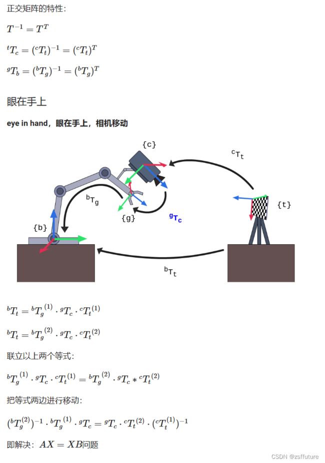
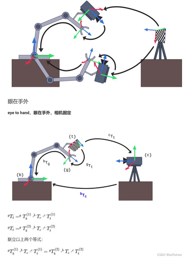
一、手眼标定的原理
图例说明:
- {b}:base基座标系
- {g}:gripper抓手坐标系
- {t}:target标定板坐标系
- {c}:camera相机坐标系


二、手眼标定的操作

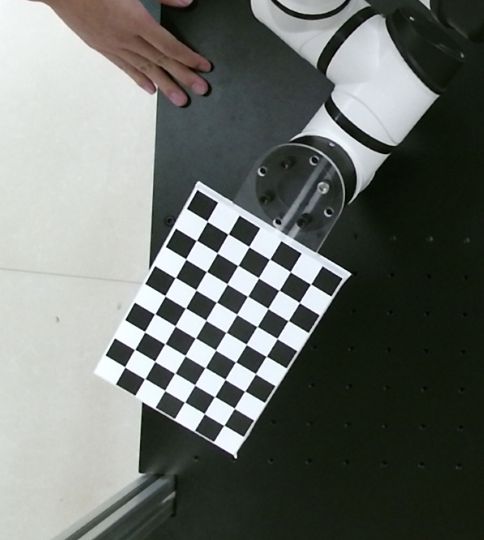
- 将标定板固定在机械臂末端
- 开启机械臂,开启摄像头
- 在距离摄像头40、60、80cm的距离上,在摄像头可见范围内,使用各种角度各拍照15-20张照片,一共45-60张。
- 同时保存照片以及对应拍照时机械臂位姿
- 准备好之前标定的相机内参
- 执行手眼标定API,得到相机在基坐标系的表达(旋转矩阵R+平移向量t)
三、自己动手实现手眼标定及验证
// Created by poplar on 19-7-25.
#include
#include
#include
#include "boost/filesystem.hpp" // includes all needed Boost.Filesystem declarations
#include
#include
#include "tinyxml/tinyxml2.h"
#include
2D与3D融合实践
根据模板抓取指定物体:
制作模板,并计算取得相机到模板的变换矩阵T1,根据实时相机中拍到的物体进行模板匹配,得到变换矩阵T0,最后和相机的外参矩阵Tc进行矩阵相乘,得到目标在世界坐标系的表示,从而进行抓取操作。
一、制作模板:求T1
-
Kinect相机拍照(得到RGB图和深度图)
01_PhotoCapture.cpp
-
检测抓取位置(u,v),根据内参及深度信息得到三个空间中的点坐标
02_PointLocator.cpp
03_TemplateMaker.cpp
-
构建坐标系得到旋转矩阵T1,转成RPY进行抓取测试
04_TestGrabTemplate.cpp
-
生成点云图用于模板匹配(进行直通滤波及降采样)
05_CreatePclCloud.cpp 验证变换矩阵
06_TemplateCloudFilter.cpp 生成剪切后的模板
- 实时的拍照得到RGB和深度图
- 合成目标点云图
- 通过直通滤波框定范围(得到感兴趣区域)
- 将感兴趣区域进行降采样(提高模板匹配效率)
二、使用模板:求T0
准备好切割后的点云template.pcd以及对应的变换矩阵T1(可以有多个)
-
Kinect相机拍照(得到RGB图和深度图)
01_PhotoCapture.cpp
-
生成目标点云图
07_TargetCloudFilter.cpp
-
进行模板与目标点云图匹配(统一进行直通滤波及降采样),得到变换矩阵T0
08_TemplateAlignment.cpp
三、进行抓取测试

09_TestGrabTarget.cpp√
T0 为目标在模板坐标系的表达 T1 为模板在相机坐标系的表达 Tc 为相机在基坐标系的表达
待优化事宜
- 安全位置判定
- 将盒子抓取到指定位置放置
- 不间断抓取多个盒子
- 准备多个模板,提高模板匹配姿态识别度
- 设置间隔,实时进行模板匹配
- 设置目标位置抓取动态延时
- 自动避障
- 其他
自己封装内外参标定工具


