前几天没想准备做点ugui效果就又找到unity的bug了,那就是和上一篇相关,我想对ugui line制作一些简单的动效,结果发现uivertex的uv字段不生效,同时发现FillMesh函数也无效,那么对我来说Graphic.OnPopulateMesh就没用了,我得想别的办法。
下面来详细说明一下我碰到的问题:
我想给绘制的line加上shader动效,所以需要uv0参数,我按照如下图计算出uv0:
代码如下:
///
/// 获取每一段“线段”的长度
///
///
///
private float[] GetLineLengths(Vector2[] poses)
{
float[] seglens = new float[poses.Length - 1];
float length = 0;
for (int i = 1; i < poses.Length; i++)
{
Vector2 fpos = poses[i - 1];
Vector2 tpos = poses[i];
float len = Vector2.Distance(fpos, tpos);
length += len;
seglens[i - 1] = length;
}
return seglens;
}
///
/// 获取vertex uv0
/// 根据距离/总长计算
///
///
///
///
private Vector2 GetVertexUV0(int findex, int tindex)
{
Vector2 uv = new Vector2(0, Mathf.Abs(tindex - 1));
if (findex != 0)
{
float len = lengths[findex - 1];
float sumlen = lengths[lengths.Length - 1];
uv = new Vector2(len / sumlen, Mathf.Abs(tindex - 1));
}
#if UNITY_EDITOR
Debug.LogWarningFormat("findex = {0} tindex = {1} uv = {2}", findex, tindex, uv);
#endif
return uv;
}
for (int i = 0; i < ptcount; i++)
{
int firstindex = i % ptslist.Count;
int secondindex = i / ptslist.Count;
UIVertex vertex = new UIVertex();
vertex.position = ptslist[firstindex][secondindex];
vertex.uv0 = GetVertexUV0(firstindex, secondindex);
vertex.uv1 = vertex.uv0;
vertex.uv2 = vertex.uv0;
vertex.uv3 = vertex.uv0;
vh.AddVert(vertex);
}
我为了测试,把uv0-3都赋值了,顺便做了个uv sample shader,如下:
Shader "Ugui/UguiUVSampleShader"
{
Properties
{
_MainTex ("Texture", 2D) = "white" {}
_MainColor("Main Color",Color) = (1,1,1,1)
}
SubShader
{
Tags { "RenderType"="Transparent" "Queue"="Transparent" }
LOD 100
Pass
{
Cull OFF
CGPROGRAM
#pragma vertex vert
#pragma fragment frag
#include "UnityCG.cginc"
struct appdata
{
float4 vertex : POSITION;
float2 uv : TEXCOORD0;
};
struct v2f
{
float2 uv : TEXCOORD0;
float4 vertex : SV_POSITION;
};
sampler2D _MainTex;
float4 _MainTex_ST;
float4 _MainColor;
v2f vert (appdata v)
{
v2f o;
o.vertex = UnityObjectToClipPos(v.vertex);
o.uv = TRANSFORM_TEX(v.uv, _MainTex);
return o;
}
fixed4 frag (v2f i) : SV_Target
{
fixed4 col = tex2D(_MainTex, i.uv);
return col;
}
ENDCG
}
}
}
结果???没效果?如图:
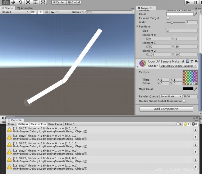
我顺便试了下color属性,发现有效果:
vertex.color = Color.green;
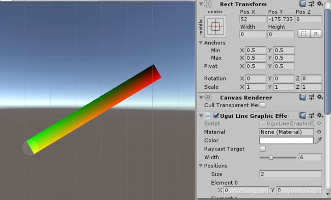
我给上面四个顶点赋值了不同的颜色,就正常渲染了,但是,这并不满足我的需求,用c#写动效,效率不见得ok。
同时我测试了一下FillMesh方式,如下:
using System.Collections;
using System.Collections.Generic;
using UnityEngine;
using UnityEngine.UI;
public class UguiMeshGraphic : Graphic
{
protected override void OnPopulateMesh(VertexHelper vh)
{
//base.OnPopulateMesh(vh);
vh.Clear();
Mesh mesh = new Mesh();
mesh.vertices = new Vector3[] { new Vector3(0, 0), new Vector3(0, 100), new Vector3(100, 100), new Vector3(100, 0) };
mesh.uv = new Vector2[] { new Vector2(0, 0), new Vector2(0, 1), new Vector2(1, 1), new Vector2(1, 0) };
mesh.triangles = new int[]
{
0,1,2,
0,2,3,
};
vh.FillMesh(mesh);
}
}
结果???别说uv sample了,连网格都构建不出来,如下:
好吧,unity2018.4.12f1 personal版本,不知道是不是版本问题(或是我的问题),我也没兴趣切换别的版本测试了(有兴趣的同学可以试试),毕竟如果这是个随机的bug,那就算我以后切换了版本还是可能遇到问题。这样的话,UnityEngine.UI.Graphic.OnPopulateMesh,我们就可以放弃了,另想他法。
还好CanvasRenderer这个组件照样能满足我们的ugui渲染需求,下面测试一下:
using System.Collections;
using System.Collections.Generic;
using UnityEngine;
public class UguiTestMeshRender : MonoBehaviour
{
public Material mat;
private void Start()
{
Mesh mesh = new Mesh();
mesh.vertices = new Vector3[] { new Vector3(0, 0), new Vector3(0, 100), new Vector3(100, 100), new Vector3(100, 0) };
mesh.uv = new Vector2[] { new Vector2(0, 0), new Vector2(0, 1), new Vector2(1, 1), new Vector2(1, 0) };
mesh.triangles = new int[]
{
0,1,2,
0,2,3,
};
CanvasRenderer crender = GetComponent<CanvasRenderer>();
crender.SetMaterial(mat, null);
crender.SetMesh(mesh);
}
}
Good,需要的效果直接就出来了:
那么,接下来我们改版c#代码:
using System.Collections;
using System.Collections.Generic;
using UnityEngine;
public class UguiLineRenderer : MonoBehaviour
{
[Range(0, 20)]
public float width = 10f;
public Vector2[] positions;
public Material mat;
private float[] lengths;
public bool isUpdate = false;
private CanvasRenderer canvasRender;
void Start()
{
canvasRender = GetComponent<CanvasRenderer>();
}
void Update()
{
if (isUpdate)
{
DrawUpdate();
isUpdate = false;
}
}
///
/// 更新绘制
///
private void DrawUpdate()
{
if (positions == null || positions.Length < 2)
{
return;
}
lengths = GetLineLengths(positions);
Mesh mesh = new Mesh();
//如果只有两个顶点
//直接生成直线即可
if (positions.Length == 2)
{
Vector2 a = positions[0];
Vector2 b = positions[1];
Vector2[] a1a2 = CalculateVerticalPoints(a, a, b, width);
Vector2[] b1b2 = CalculateVerticalPoints(b, a, b, width);
Vector2 a1 = a1a2[0];
Vector2 a2 = a1a2[1];
Vector2 b1 = b1b2[0];
Vector2 b2 = b1b2[1];
mesh.vertices = new Vector3[] { a2, a1, b1, b2 };
mesh.uv = new Vector2[] { new Vector2(0, 0), new Vector2(0, 1), new Vector2(1, 1), new Vector2(1, 0) };
mesh.triangles = new int[]
{
0,1,2,
0,2,3,
};
}
else
{
//如果是多顶点组成的矩形数组
//储存A1A2/B1B2...Z1Z2
List<Vector2[]> ptslist = new List<Vector2[]>();
//先储存A1A2
{
Vector2[] a1a2 = CalculateVerticalPoints(positions[0], positions[0], positions[1], width);
ptslist.Add(a1a2);
}
//再储存B1B2...Y1Y2
{
for (int i = 1; i < positions.Length - 1; i++)
{
Vector2 a = positions[i - 1];
Vector2 b = positions[i];
Vector2 c = positions[i + 1];
Vector2 d = positions[i]; //d=c
Vector2[] a1a2 = CalculateVerticalPoints(a, a, b, width);
Vector2[] b1b2 = CalculateVerticalPoints(b, a, b, width);
Vector2[] c1c2 = CalculateVerticalPoints(c, d, c, width);
Vector2[] d1d2 = CalculateVerticalPoints(d, d, c, width);
Vector2 a1 = a1a2[0];
Vector2 a2 = a1a2[1];
Vector2 b1 = b1b2[0];
Vector2 b2 = b1b2[1];
Vector2 c1 = c1c2[0];
Vector2 c2 = c1c2[1];
Vector2 d1 = d1d2[0];
Vector2 d2 = d1d2[1];
//如果线段AB和DC平行
if (IsVector2Approximiate(b1, d1) && IsVector2Approximiate(b2, d2))
{
//任意储存b1b2或d1d2
ptslist.Add(b1b2);
}
//如果线段AB和DC相交
else
{
Vector2 crossb1 = CalculateLineCross(a1, b1, c1, d1);
Vector2 crossb2 = CalculateLineCross(a2, b2, c2, d2);
//储存交点b1b2
ptslist.Add(new Vector2[] { crossb1, crossb2 });
}
}
}
//最后储存Z1Z2
{
Vector2[] z1z2 = CalculateVerticalPoints(positions[positions.Length - 1], positions[positions.Length - 2], positions[positions.Length - 1], width);
ptslist.Add(z1z2);
}
//再来构建网格
int ptcount = ptslist.Count * 2;
Vector3[] vertices = new Vector3[ptcount];
Vector2[] uvs = new Vector2[ptcount];
for (int i = 0; i < ptcount; i++)
{
int firstindex = i % ptslist.Count;
int secondindex = i / ptslist.Count;
vertices[i] = ptslist[firstindex][secondindex];
uvs[i] = GetVertexUV0(firstindex, secondindex);
}
int quadcount = ptslist.Count - 1;
List<int> trilist = new List<int>();
for (int i = 0; i < quadcount; i++)
{
//quad左上角顺时针
int topleftindex = i;
int bottomleftindex = i + ptslist.Count;
trilist.AddRange(new int[] { topleftindex, topleftindex + 1, bottomleftindex });
trilist.AddRange(new int[] { topleftindex + 1, bottomleftindex + 1, bottomleftindex });
}
mesh.vertices = vertices;
mesh.uv = uvs;
mesh.triangles = trilist.ToArray();
}
canvasRender.SetMaterial(mat, null);
canvasRender.SetMesh(mesh);
}
///
/// 获取每一段“线段”的长度
///
///
///
private float[] GetLineLengths(Vector2[] poses)
{
float[] seglens = new float[poses.Length - 1];
float length = 0;
for (int i = 1; i < poses.Length; i++)
{
Vector2 fpos = poses[i - 1];
Vector2 tpos = poses[i];
float len = Vector2.Distance(fpos, tpos);
length += len;
seglens[i - 1] = length;
}
return seglens;
}
///
/// 获取vertex uv0
/// 根据距离/总长计算
///
///
///
///
private Vector2 GetVertexUV0(int findex, int tindex)
{
Vector2 uv = new Vector2(0, Mathf.Abs(tindex - 1));
if (findex != 0)
{
float len = lengths[findex - 1];
float sumlen = lengths[lengths.Length - 1];
uv = new Vector2(len / sumlen, Mathf.Abs(tindex - 1));
}
#if UNITY_EDITOR
Debug.LogWarningFormat("findex = {0} tindex = {1} uv = {2}", findex, tindex, uv);
#endif
return uv;
}
///
/// 判断两vector2坐标相近
///
///
///
///
private bool IsVector2Approximiate(Vector2 a, Vector2 b)
{
if (Mathf.Approximately(a.x, b.x) && Mathf.Approximately(a.y, b.y))
{
return true;
}
return false;
}
///
/// 计算两射线交点
///
///
///
///
///
///
private Vector2 CalculateLineCross(Vector2 p1, Vector2 p2, Vector2 p4, Vector2 p3)
{
//构建直线参数k和a
float k1 = (p2.y - p1.y) / (p2.x - p1.x);
float a1 = p2.y - k1 * p2.x;
float k2 = (p3.y - p4.y) / (p3.x - p4.x);
float a2 = p3.y - k2 * p3.x;
//根据求解计算交点
float y = (k2 * a1 - k1 * a2) / (k2 - k1);
float x = 0;
if (k1 != 0)
{
x = (y - a1) / k1;
}
else if (k2 != 0)
{
x = (y - a2) / k2;
}
return new Vector2(x, y);
}
///
/// 计算A1和A2
/// po代表pa或者pb
/// 和本来的pa,pb分开为了通用
///
///
///
///
///
///
private Vector2[] CalculateVerticalPoints(Vector2 po, Vector2 pa, Vector2 pb, float wid)
{
//先计算出a3
float halfwid = wid / 2f;
Vector2 npapb = (pb - pa).normalized;
Vector2 pa3 = npapb * halfwid;
//再根据矩阵旋转计算出a1,a2
Vector2 pa1 = po + CalculatePointRotate(pa3, 90);
Vector2 pa2 = po + CalculatePointRotate(pa3, 270);
#if UNITY_EDITOR
Debug.LogFormat("po = {0} pa3 = {1} pa1 = {2} pa2 = {3}", po, pa3, pa1, pa2);
#endif
return new Vector2[] { pa1, pa2 };
}
///
/// 计算f旋转ang角度后的t
///
///
///
///
private Vector2 CalculatePointRotate(Vector2 f, float ang)
{
float rad = ang * Mathf.Deg2Rad;
Matrix2x2 m2x2 = new Matrix2x2();
m2x2.m00 = Mathf.Cos(rad);
m2x2.m01 = -Mathf.Sin(rad);
m2x2.m10 = Mathf.Sin(rad);
m2x2.m11 = -Mathf.Cos(rad);
Vector2 t = m2x2 * f;
return t;
}
public class Matrix2x2
{
public float m00;
public float m01;
public float m10;
public float m11;
public static Vector2 operator *(Matrix2x2 m2x2, Vector2 v2)
{
float x = m2x2.m00 * v2.x + m2x2.m01 * v2.y;
float y = m2x2.m10 * v2.x + m2x2.m11 * v2.y;
return new Vector2(x, y);
}
}
}
效果如下:
这样的话,uv0就生效了,那么接下来我们写两个effect shader,比如虚线:
Shader "Ugui/UguiDottedLineShader"
{
Properties
{
_MainTex ("Texture", 2D) = "white" {}
_MainColor("Color",Color) = (1,1,1,1)
_Pow("Pow",Range(0,1000)) = 200
}
SubShader
{
Tags { "RenderType"="Transparent" "Queue"="Transparent" }
LOD 100
Pass
{
CGPROGRAM
#pragma vertex vert
#pragma fragment frag
#include "UnityCG.cginc"
struct appdata
{
float4 vertex : POSITION;
float2 uv : TEXCOORD0;
};
struct v2f
{
float2 uv : TEXCOORD0;
float4 vertex : SV_POSITION;
};
sampler2D _MainTex;
float4 _MainTex_ST;
float4 _MainColor;
float _Pow;
v2f vert (appdata v)
{
v2f o;
o.vertex = UnityObjectToClipPos(v.vertex);
o.uv = TRANSFORM_TEX(v.uv, _MainTex);
return o;
}
fixed4 frag (v2f i) : SV_Target
{
fixed4 col = _MainColor;
float s = sin(i.uv*_Pow);
if(s<0)
{
discard;
}
return col;
}
ENDCG
}
}
}
效果如下:
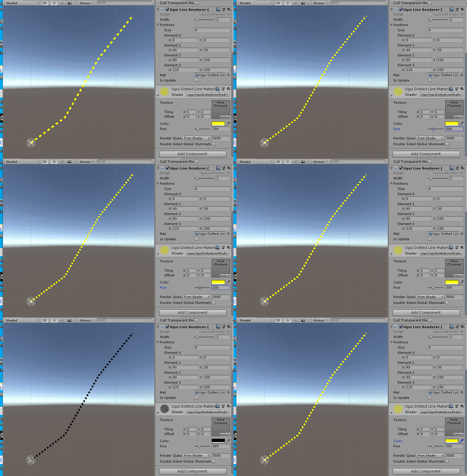
效果原理也简单:就是根据sin(uv.x)进行周期性的discard pixel,就可以做成虚线。
再来一个移动的效果:
Shader "Ugui/UguiLineMotionShader"
{
Properties
{
_MainTex ("Texture", 2D) = "white" {}
_BgColor("Bg Color",Color) = (1,1,1,1)
_ForeColor("Fore Color",Color) = (1,1,1,1)
_Speed("Speed",Range(0,2)) = 1
_Pow("Pow",Range(0,100)) = 10
}
SubShader
{
Tags { "RenderType"="Transparent" "Queue"="Transparent" }
LOD 100
Pass
{
CGPROGRAM
#pragma vertex vert
#pragma fragment frag
#include "UnityCG.cginc"
struct appdata
{
float4 vertex : POSITION;
float2 uv : TEXCOORD0;
};
struct v2f
{
float2 uv : TEXCOORD0;
float4 vertex : SV_POSITION;
};
sampler2D _MainTex;
float4 _MainTex_ST;
float4 _BgColor;
float4 _ForeColor;
float _Speed;
float _Pow;
v2f vert (appdata v)
{
v2f o;
o.vertex = UnityObjectToClipPos(v.vertex);
o.uv = TRANSFORM_TEX(v.uv, _MainTex);
return o;
}
fixed4 frag (v2f i) : SV_Target
{
i.uv.x -= _Time.y * _Speed;
float s = sin(i.uv.x * _Pow);
fixed4 col = lerp(_ForeColor,_BgColor,s);
return col;
}
ENDCG
}
}
}
效果如下:
原理也比较简单:就是根据uv.x进行偏移,通过sin函数制作周期的波峰,就行了。
好,今天就到这里,以后有时间继续。