企业网三层构架实验
实验题目如下:
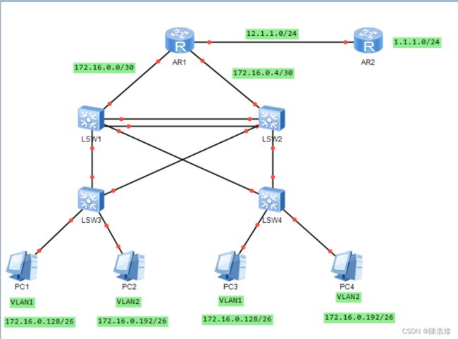
实验拓扑如下:
实验要求如下:
【1】内网IP地址172.16.0.0/16 合理分配
【2】SW1/2之间互为备份
【3】VRBP/STP/VLAN/TRUNK均使用
【4】所有PC通过DHCP获取IP地址
实验思路如下:
(1)合理的IP配置
(2)创建eth-trunk
(3)设置trunk干道
(4)创建VLAN和划分VLAN
(5)生成树
(6)开启SVI
(7)运行VRRP
(8)路由配置
实验步骤如下:
1、IP配置
指令如下:
R1:
[r2]int g0/0/0
[r2-GigabitEthernet0/0/0]ip ad 172.16.0.2 30
[r2-GigabitEthernet0/0/0]int g0/0/2
[r2-GigabitEthernet0/0/2]ip ad 172.16.0.6 30
[r2-GigabitEthernet0/0/2]int g0/0/1
[r2-GigabitEthernet0/0/1]ip ad 12.1.1.1 24
R2:
[r1]int lo0
[r1-LoopBack0]ip ad 1.1.1.1 24
[r1-LoopBack0]int g0/0/0
[r1-GigabitEthernet0/0/0]ip ad 12.1.1.2 24
2、创建eth-trunk
指令如下:
SW1:
[sw1]int Eth-Trunk 0
[sw1-Eth-Trunk0]q
[sw1]int g0/0/23
[sw1-GigabitEthernet0/0/23]eth-trunk 0
[sw1-GigabitEthernet0/0/23]int g0/0/24
[sw1-GigabitEthernet0/0/24]eth-trunk 0
SW2:
[sw2]int Eth-Trunk 0
[sw2-Eth-Trunk0]q
[sw2]int g0/0/23
[sw2-GigabitEthernet0/0/23]eth-trunk 0
[sw2-GigabitEthernet0/0/23]int g0/0/24
[sw2-GigabitEthernet0/0/24]eth-trunk 0
3、设置trunk干道
指令如下:
SW1:
[sw1]port-group group-member GigabitEthernet 0/0/2 to GigabitEthernet 0/0/3 Eth-Trunk 0
[sw1-port-group]port link-type trunk
[sw1-port-group]port trunk allow-pass vlan
SW2:
[sw2]port-group group-member GigabitEthernet 0/0/2 to GigabitEthernet 0/0/3 Eth-Trunk 0
[sw2-port-group]port link-type trunk
[sw2-port-group]port trunk allow-pass vlan  2
SW3:
[sw3]port-group group-member GigabitEthernet 0/0/1 to GigabitEthernet 0/0/2
[sw3-port-group]port link-type trunk
[sw3-port-group]port trunk allow-pass vlan 2
SW4:
[sw4]port-group group-member GigabitEthernet 0/0/1 to GigabitEthernet 0/0/2
[sw4-port-group]port link-type trunk
[sw4-port-group]port trunk allow-pass vlan 2
4、创建VLAN和划分VLAN
指令如下:
SW1:
[sw1]vlan 2SW2:
[sw2]vlan 2SW3:
[sw3]vlan 2
[sw3]int Eth0/0/2
[sw3-Ethernet0/0/2]port link-type access
[sw3-Ethernet0/0/2]port default vlan 2
SW4:
[sw4]vlan 2[sw4]int e0/0/2
[sw4-Ethernet0/0/2]port link-type access
[sw4-Ethernet0/0/2]port default vlan 25、生成树
指令如下:
SW1:
[sw1]stp mode mstp
[sw1]stp enable
[sw1]stp region-configuration
[sw1-mst-region]region-name a
[sw1-mst-region]instance 1 vlan 1
[sw1-mst-region]instance 2 vlan 2
[sw1-mst-region]active region-configuration
[sw1]stp instance 1 root primary
[sw1]stp instance 2 root secondarySW2:
[sw2]stp mode mstp
[sw2]stp enable
[sw2]stp region-configuration
[sw2-mst-region]region-name a
[sw2-mst-region]instance 1 vlan 1
[sw2-mst-region]instance 2 vlan 2
[sw2-mst-region]active region-configuration
[sw2]stp instance 2 root primary
[sw2]stp instance 1 root secondarySW3:
[sw3]stp mode mstp
[sw3]stp enable
[sw3]stp region-configuration
[sw3-mst-region]region-name a
[sw3-mst-region]instance 1 vlan 1
[sw3-mst-region]instance 2 vlan 2
[sw3-mst-region]active region-configuration
[sw3]port-group group-member Ethernet 0/0/1 to Ethernet 0/0/2
[sw3-port-group]stp edged-port enableSW4:
[sw4]stp mode mstp
[sw4]stp enable
[sw4]stp region-configuration
[sw4-mst-region]region-name a
[sw4-mst-region]instance 1 vlan 1
[sw4-mst-region]instance 2 vlan 2
[sw4-mst-region]active region-configuration
[sw4]port-group group-member Ethernet 0/0/1 to Ethernet 0/0/2
[sw4-port-group]stp edged-port enable6、开启SVI
指令如下:
SW1:
[sw1]interface vlan 1
[sw1-Vlanif1]ip ad 172.16.1.1 25
[sw1]interface vlan 2
[sw1-Vlanif2]ip ad 172.16.1.129 25
SW2:
[sw2]interface vlan 1
[sw2-Vlanif1]ip ad 172.16.1.2 25
[sw2]interface vlan 2
[sw2-Vlanif2]ip ad 172.16.1.130 25
7、VRRP
指令如下:
SW1:
[sw1]interface vlan 1
[sw1-Vlanif1]vrrp vrid 1 virtual-ip 172.16.1.126
[sw1-Vlanif1]vrrp vrid 1 priority 120
[sw1-Vlanif1]vrrp vrid 1 track interface GigabitEthernet 0/0/1 reduced 30
[sw1]interface vlan 2
[sw1-Vlanif2]vrrp vrid 1 virtual-ip 172.16.1.254
SW2:
[sw2]interface vlan 1
[sw2-Vlanif1]vrrp vrid 1 virtual-ip 172.16.1.126
[sw2]interface vlan 2
[sw2-Vlanif2]vrrp vrid 1 vir
[sw2-Vlanif2]vrrp vrid 1 virtual-ip 172.16.1.254
[sw2-Vlanif2]vrrp vrid 1 priority 120
[sw2-Vlanif2]vrrp vrid 1 track interface GigabitEthernet 0/0/1 reduced 30
8、DHCP
指令如下:
准备如下:
SW1:
[sw1]vlan 100
[sw1]int g0/0/1
[sw1-GigabitEthernet0/0/1]port link-type access
[sw1-GigabitEthernet0/0/1]p d vlan 100
[sw1-GigabitEthernet0/0/1]int vlan 100
[sw1-Vlanif100]ip ad 172.16.0.1 30
SW2:
[sw2]vlan 100
[sw2-vlan100]int vlan 100
[sw2-Vlanif100]ip ad 172.16.0.5 30
[sw2-Vlanif100]int g0/0/1
[sw2-GigabitEthernet0/0/1]port link-type access
[sw2-GigabitEthernet0/0/1]p d vlan 100
配置OSPF:
指令如下:
R2:
[r2]ospf 1 router-id 1.1.1.1
[r2-ospf-1]area 0
[r2-ospf-1-area-0.0.0.0]network 172.16.0.0 0.0.0.255
SW1:
[sw1]ospf 1 router-id 1.1.1.2
[sw1-ospf-1]area 0
[sw1-ospf-1-area-0.0.0.0]network 172.16.0.1 0.0.0.0
[sw1-ospf-1-area-0.0.0.0]q
[sw1-ospf-1]area 1
[sw1-ospf-1-area-0.0.0.1]network 172.16.1.1 0.0.0.0
[sw1-ospf-1-area-0.0.0.1]network 172.16.1.129 0.0.0.0
SW2:
[sw2]ospf 1 router-id 2.2.2.2
[sw2-ospf-1]area 0
[sw2-ospf-1-area-0.0.0.0]network 172.16.0.5 0.0.0.0
[sw2-ospf-1-area-0.0.0.0]q
[sw2-ospf-1]area 1
[sw2-ospf-1-area-0.0.0.1]network 172.16.1.2 0.0.0.0
[sw2-ospf-1-area-0.0.0.1]network 172.16.1.130 0.0.0.0
9、缺省路由
指令如下:
R2:
[r2]ip route-static 0.0.0.0 0.0.0.0 12.1.1.2
[r2]ospf 1
[r2-ospf-1]default-route-advertis
配置nat
指令如下:
R2:
[r2]acl 2000
[r2-acl-basic-2000]rule permit source 172.16.0.0 0.0.255.255
[r2-acl-basic-2000]int g0/0/1
[r2-GigabitEthernet0/0/1]nat outbound 2000
10、测试如下:
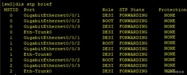
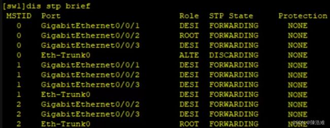
生成树:
SW1:
SW2:
PC2:
PC4:


