ODrive0.5.5源码分析(5) FOC相关
作者:沉尸([email protected])
前言:
1)本章探讨FOC控制的几个过程分别是在那些函数中进行调用?
2)这些函数在什么时间节点被调用?
3)最后剖析FOC控制代码中的详细计算细节。
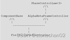
先画出FOC相关的类图:
简洁类图:
图1
详细类图:
图2
说明:上图中纯虚函数特别用红色标识。
经过前面几篇文章讲述的“ADC的处理”以及“时钟和定时器”方面的内容,我们已经知道了3相电流是在哪个时间节点被采集到的,且在哪个函数里面从寄存器中取出然后放入到对应变量中了。
于是,FOC的相关控制就可以开始了:
“MotorControl\motor.cpp”中函数“current_meas_cb()”:
图3
“MotorControl\motor.hpp”有定义:
PhaseControlLaw<3>* control_law_;
看上面类图,可知:
control_law_->on_measurement 实际上调用AlphaBetaFrameController:: on_measurement
贴出代码:(来自“MotorControl\foc.cpp”)
| 5 6 7 8 9 10 11 12 13 14 15 16 17 18 19 20 21 |
Motor::Error AlphaBetaFrameController::on_measurement( std::optional<float> vbus_voltage, std::optional uint32_t input_timestamp) { std::optional
if (currents.has_value()) { // Clarke transform Ialpha_beta = { (*currents)[0], one_by_sqrt3 * ((*currents)[1] - (*currents)[2]) }; }
return on_measurement(vbus_voltage, Ialpha_beta, input_timestamp); } |
Ln14 ~ Ln17:
通过Clarke变换计算出了“Ialpha_beta”
计算公式参考《马达控制之FOC原理》
中的式子(2-3)
Ln20:
调用了同一个类“AlphaBetaFrameController”中另一个 “on_measurement()” 重载函数(参数类型不同),但是这个函数是个纯虚函数:
图5
最后的结果就是调用继承了“AlphaBetaFrameController”的派生类中“on_measurement()”的实现,比如:
“ResistanceMeasurementControlLaw::measurement()”
“FieldOrientedController::on_measurement()”
因为“control_law_”虽然是一个基类指针,它被赋值肯定会是“ResistanceMeasurementControlLaw”或者“FieldOrientedController”等等这样的派生类对象。从源码中摘录证实如下:
图6
我们继续来看“FieldOrientedController::on_measurement”做了些啥工作:
图7
简单地将计算出来的值保存到相应的变量中而已!!!
现在,通过Clarke计算出了Iα 和 Iβ ,那么后面继续的处理在哪调用呢?
图8
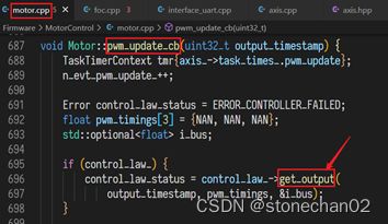
从类图可知:调用“PhaseControlLaw
实际上会调用“AlphaBetaFrameController::get_output()”。
图9
“AlphaBetaFrameController:: get_alpha_beta_output()”是一个纯虚函数,所以我们要看派生类中的相应函数“FieldOrientedController::get_alpha_beta_output()”
图10
这个函数里面进行了“Park”变换、“反Park”变换,转换成pwm控制参数等
现在脉络基本清晰了:
1)“current_meas_cb()”中调用FOC相关的“on_measurement()”,进行了“Clarke”变换,获取了:Iα 和 Iβ 等
2)“pwm_update_cb()”中调用FOC相关的“get_output()”,“get_output()”又会调用“get_alpha_beta_output()”来进行一些列的“Park”变换、“反Park”变换等,计算出的结果在“get_output()”里面再最后计算出pwm控制的占空比值。
现在再来看看上面两个“cb”函数的调用地方以及函数调用和ADC触发的时序图:
图11
现在对于FOC相关控制的调用脉络就很清晰了吧?
刚才为了抓主线,对上面FOC的几个函数没有详细剖析。
现在我们先来看函数“get_alpha_beta_output”(MotorControl\foc.cpp)
| 66 67 68 69 70 71 72 73 74 75 76 77 78 79 80 81 82 83 84 85 86 87 88 89 90 91 92 93 94 95 96 97 98 99 100 101 102 103 104 105 106 107 108 109 110 111 112 113 114 115 116 117 118 119 120 121 122 123 124 125 126 127 128 129 130 131 132 133 134 135 136 137 138 139 140 141 142 143 144 145 146 147 148 149 150 157 152 153 154 155 156 157 158 159 160 161 162 163 164 165 166 167 168 169 170 171 172 173 174 175 176 177 178 179 180 181 182 |
ODriveIntf::MotorIntf::Error FieldOrientedController::get_alpha_beta_output( uint32_t output_timestamp, std::optional std::optional<float>* ibus) { if (!vbus_voltage_measured_.has_value() || !Ialpha_beta_measured_.has_value()) { // FOC didn't receive a current measurement yet. return Motor::ERROR_CONTROLLER_INITIALIZING; } else if (abs((int32_t)(i_timestamp_ - ctrl_timestamp_)) > MAX_CONTROL_LOOP_UPDATE_TO_CURRENT_UPDATE_DELTA) { // Data from control loop and current measurement are too far apart. return Motor::ERROR_BAD_TIMING; } // TODO: improve efficiency in case PWM updates are requested at a higher // rate than current sensor updates. In this case we can reuse mod_d and // mod_q from a previous iteration. if (!Vdq_setpoint_.has_value()) { return Motor::ERROR_UNKNOWN_VOLTAGE_COMMAND; } else if (!phase_.has_value() || !phase_vel_.has_value()) { return Motor::ERROR_UNKNOWN_PHASE_ESTIMATE; } else if (!vbus_voltage_measured_.has_value()) { return Motor::ERROR_UNKNOWN_VBUS_VOLTAGE; } auto [Vd, Vq] = *Vdq_setpoint_; // auto 推导出 std::tuple float phase = *phase_; float phase_vel = *phase_vel_; float vbus_voltage = *vbus_voltage_measured_; std::optional // Park transform if (Ialpha_beta_measured_.has_value()) { auto [Ialpha, Ibeta] = *Ialpha_beta_measured_; float I_phase = phase + phase_vel * ((float)(int32_t)(i_timestamp_ - ctrl_timestamp_) / (float)TIM_1_8_CLOCK_HZ); float c_I = our_arm_cos_f32(I_phase); float s_I = our_arm_sin_f32(I_phase); Idq = { c_I * Ialpha + s_I * Ibeta, c_I * Ibeta - s_I * Ialpha }; Id_measured_ += I_measured_report_filter_k_ * (Idq->first - Id_measured_); Iq_measured_ += I_measured_report_filter_k_ * (Idq->second - Iq_measured_); } else { Id_measured_ = 0.0f; Iq_measured_ = 0.0f; } float mod_to_V = (2.0f / 3.0f) * vbus_voltage; float V_to_mod = 1.0f / mod_to_V; float mod_d; float mod_q; if (enable_current_control_) { // Current control mode if (!pi_gains_.has_value()) { return Motor::ERROR_UNKNOWN_GAINS; } else if (!Idq.has_value()) { return Motor::ERROR_UNKNOWN_CURRENT_MEASUREMENT; } else if (!Idq_setpoint_.has_value()) { return Motor::ERROR_UNKNOWN_CURRENT_COMMAND; } auto [p_gain, i_gain] = *pi_gains_; auto [Id, Iq] = *Idq; auto [Id_setpoint, Iq_setpoint] = *Idq_setpoint_; float Ierr_d = Id_setpoint - Id; float Ierr_q = Iq_setpoint - Iq; // Apply PI control (V{d,q}_setpoint act as feed-forward terms in this mode) mod_d = V_to_mod * (Vd + v_current_control_integral_d_ + Ierr_d * p_gain); mod_q = V_to_mod * (Vq + v_current_control_integral_q_ + Ierr_q * p_gain); // Vector modulation saturation, lock integrator if saturated // TODO make maximum modulation configurable float mod_scalefactor = 0.80f * sqrt3_by_2 * 1.0f / std::sqrt(mod_d * mod_d + mod_q * mod_q); if (mod_scalefactor < 1.0f) { mod_d *= mod_scalefactor; mod_q *= mod_scalefactor; // TODO make decayfactor configurable v_current_control_integral_d_ *= 0.99f; v_current_control_integral_q_ *= 0.99f; } else { v_current_control_integral_d_ += Ierr_d * (i_gain * current_meas_period); v_current_control_integral_q_ += Ierr_q * (i_gain * current_meas_period); } } else { // Voltage control mode mod_d = V_to_mod * Vd; mod_q = V_to_mod * Vq; } // Inverse park transform float pwm_phase = phase + phase_vel * ((float)(int32_t)(output_timestamp - ctrl_timestamp_) / (float)TIM_1_8_CLOCK_HZ); float c_p = our_arm_cos_f32(pwm_phase); float s_p = our_arm_sin_f32(pwm_phase); float mod_alpha = c_p * mod_d - s_p * mod_q; float mod_beta = c_p * mod_q + s_p * mod_d; // Report final applied voltage in stationary frame (for sensorless estimator) final_v_alpha_ = mod_to_V * mod_alpha; final_v_beta_ = mod_to_V * mod_beta; *mod_alpha_beta = {mod_alpha, mod_beta}; if (Idq.has_value()) { auto [Id, Iq] = *Idq; *ibus = mod_d * Id + mod_q * Iq; power_ = vbus_voltage * (*ibus).value(); }
return Motor::ERROR_NONE; } |
根据前文中分析,我们再把调用的层次复述一遍:
ControlLoop_IRQHandler
current_meas_cb
pwm_update_cb
get_output
get_alpha_beta_output
Ln73:
代码中关于“时间戳”的地方有点多,后面准备专门开一个专题,这里暂时省略。
Ln78 ~ Ln88:
这里回头看图12
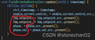
图中的A箭头和B箭头,其中B箭头处就是我们现在分析的代码的大概执行点;A箭头所指处为“control_loop_cb()”执行的过程,其中包括了总线电压的update、FOC控制的“update”,也就是调用“FieldOrientedController::update”
图中红框中的变量被update,再来理解Ln82 ~ Ln88之间的判断:
if (!Vdq_setpoint_.has_value()) {
就很容易理解了,因为正常情况下它们是会被update的(有值)。
Ln90:
![]()
这里auto会推导出 std::tuple
Ln98 ~ Ln112:
Park变换的过程,对照《马达控制之FOC原理》中的公式:
再对着源代码,完全一致。
Ln139 ~ Ln140:
PI控制
注意:计算出来的“mod_d”和“mod_q”是一个针对2/3Ud 的“比值”
Ln163 ~ Ln167:
反Park变换,参考《马达控制之FOC原理》中的公式:
Ln173:
这里要特别注意一下,通过反park变换后获得的数据均是针对“2/3Ud ”的比值,这一点在SVM函数中会有呼应
函数“get_output()”代码:
| Motor::Error AlphaBetaFrameController::get_output( uint32_t output_timestamp, float (&pwm_timings)[3], std::optional<float>* ibus) { std::optional Motor::Error status = get_alpha_beta_output(output_timestamp, &mod_alpha_beta, ibus);
if (status != Motor::ERROR_NONE) { return status; } else if (!mod_alpha_beta.has_value() || is_nan(mod_alpha_beta->first) || is_nan(mod_alpha_beta->second)) { return Motor::ERROR_MODULATION_IS_NAN; } auto [tA, tB, tC, success] = SVM(mod_alpha_beta->first, mod_alpha_beta->second); if (!success) { return Motor::ERROR_MODULATION_MAGNITUDE; } pwm_timings[0] = tA; pwm_timings[1] = tB; pwm_timings[2] = tC; return Motor::ERROR_NONE; } |
上面的代码结构很清晰,这里直接深入到SVM函数中分析一下即可:
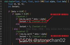
采取的是先分象限,再从象限中分出扇区:
结合我们的文章《马达控制之FOC原理》中“6.1合成矢量Uref![]() 所处扇区N 的判断 ”
所处扇区N 的判断 ”
再来看源代码中怎么判断的:
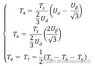
扇区判断结束,现在开始计算时间,我们贴出《马达控制之FOC原理》中的公式(以第1扇区为例)
变一下形:
再来看源代码:
格式已经对上,再来回顾一下前面分析Ln173时的一句话:
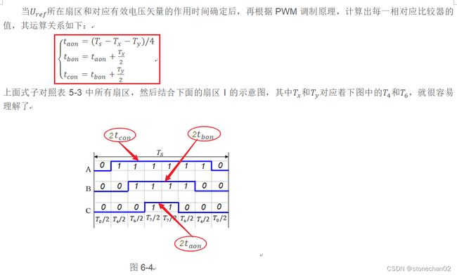
现在就完全清晰了,源码中的tA,tB和tC对应的是定时器之比较器CCR值,具体计算也在《马达控制之FOC原理》中可以找到, 这里贴出来:
细细比较,会发现我们理论中的公式和源代码还有一个2倍关系,理论中公式:
taon=(Ts-Tx-Ty)/4
而源代码中是:
tA = (1.0f - t1 - t2) * 0.5f;
再来看源代码:
看上图箭头中,实际上乘以了“1/2”周期值,于是理论和实践完美匹配!
