matlab实例一之Forward Collision Warning Using Sensor Fusion (视觉和毫米波雷达)
matlab官网介绍见
https://ww2.mathworks.cn/help/driving/examples/forward-collision-warning-using-sensor-fusion.html
此示例显示如何通过融合来自视觉和雷达传感器的数据来跟踪车辆前方的物体来执行前向碰撞警告。
一、本例中使用的传感器是:
1.视觉传感器,提供观察对象的列表及其分类和有关车道边界的信息。每秒报告对象列表10次。每秒报告20次车道边界。
2.具有中程和长程模式的雷达传感器,其提供了未分类的观察对象的列表。每秒报告对象列表20次。
3.IMU(惯性测量单元,一个IMU包含了三个单轴的加速度计和三个单轴的陀螺),每秒20次报告自我车辆的速度和转弯率。
4.摄像机,录制了汽车前方场景的视频剪辑。注意:跟踪器不使用此视频,仅用于在视频上显示跟踪结果以进行验证。
二、提供前向碰撞警告的过程包括以下步骤:
1.从传感器获取数据。
2.融合传感器数据以获得轨道列表,即车辆前方物体的估计位置和速度。
3.根据曲目和FCW标准发出警告。FCW标准基于Euro NCAP AEB测试程序,并考虑到汽车前方物体的相对距离和相对速度。
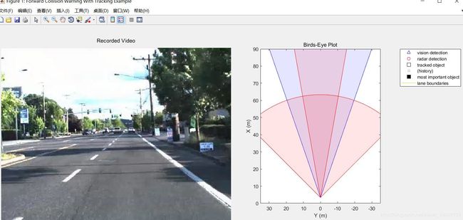
此示例中的可视化使用monoCamera(单目相机传感器,需要配置)和完成birdsEyePlot(鸟瞰图)
开始代码解读
首先进行显示
%设置显示
[videoReader, videoDisplayHandle, bepPlotters, sensor] = helperCreateFCWDemoDisplay('01_city_c2s_fcw_10s.mp4', 'SensorConfigurationData.mat');
————————————————————————————————————————————
1.函数helperCreateFCWDemoDisplay
函数function:
function [videoReader, videoDisplayHandle, bepPlotters, sensor] = helperCreateFCWDemoDisplay(videoFileName, sensorConfigurationFileName)

videoReader = VideoReader(videoFileName);
height = videoReader.Height;
width  = videoReader.Width;
frame = readFrame(videoReader);

% Define container figure
toolBarSize = 60; % Add some pixels to allow toolbars to show on top of the figure
figurePosition = getFigurePosition(height+toolBarSize, width*2); % Twice the size to allow video and bird's-eye plot
f = figure('Position', figurePosition, 'Name', 'Forward Collision Warning With Tracking Example');

% Define the video objects
hVideoAxes = axes(f, 'Units', 'Normal', 'Position', [0.01 0.01 0.49 0.88]);
videoDisplayHandle = createFCWDemoVideoDisplay(frame, hVideoAxes);

% Define the birdsEyePlot and plotters
bepAxes = axes(f, 'Units', 'Normal', 'Position', [0.55 0.1 0.44 0.78]);
bepPlotters = helperCreateFCWDemoBirdsEyePlot(sensorConfigurationFileName, bepAxes);

% Load the monoCamera object for on-video display.
load('FCWDemoMonoCameraSensor.mat', 'sensor')

% Reset the video reader to the first frame
videoReader.CurrentTime =0;
end
关于帮助:
helperCreateFCWDemoDisplay Creates the display window for the forward collision demo
This is an example helper function and is subject to change in future
releases.
This helper function creates the display for the forward collision
warning example.
Please note: a helper function may change without notice
简而言之就是此辅助函数创建一个演示窗口 即
具体helperCreateFCWDemoDisplay(mp4文件,传感器配置文件)解读:
①videoReader = VideoReader(videoFileName);
读取包含视频数据的文件 返回包含各种属性的结构体
如用D = v.Height读取视频文件的属性
frame = readFrame(videoReader);
读取一帧视频 ,frame为一个矩阵,包含像素信息和数据类型
②关于figure函数的用法:
https://blog.csdn.net/qq_30387863/article/details/80301996
f = figure(‘Visible’, ‘off’);是使得matlab不显示figure界面
getFigurePosition也是自定义函数
函数function
%% Calculate a Window Size
% The |getWindowLocation| function calculates the size of the display
% window. The window will display a video on the left hald and a bird's-eye
% plot on the right so the window width will be exactly twice the width of
% the video and will have the same height.
function figurePosition = getFigurePosition(height, width)
screenMargin = [0, 100];   % [left, top]
f = figure('Visible', 'off');
defPosition = get(f, 'Position');
figurePosition = [max(defPosition(1) + defPosition(3) - width, screenMargin(1)), max(defPosition(2) + defPosition(4) - height, screenMargin(2)), width, height];
close(f);
end
输入视频的长和宽
screenMargin屏幕余量
pos = get(gcf, ‘Position’);这个运行结果是4个数字,这4个数字分别表示figure框的——
[pos(1) pos(2)]为绘图框左下点的坐标 pos(3):长 pos(4):宽 详细解释:
https://blog.csdn.net/dongyanwen6036/article/details/79746219
也就是 和显示屏有关

以防止出现这种情况
视频跑到显示屏外面去了
figurePosition = [max(defPosition(1) + defPosition(3) - width, screenMargin(1)), max(defPosition(2) + defPosition(4) - height, screenMargin(2)), width, height];
这个max方法存疑
2019.7.14更新
解释max: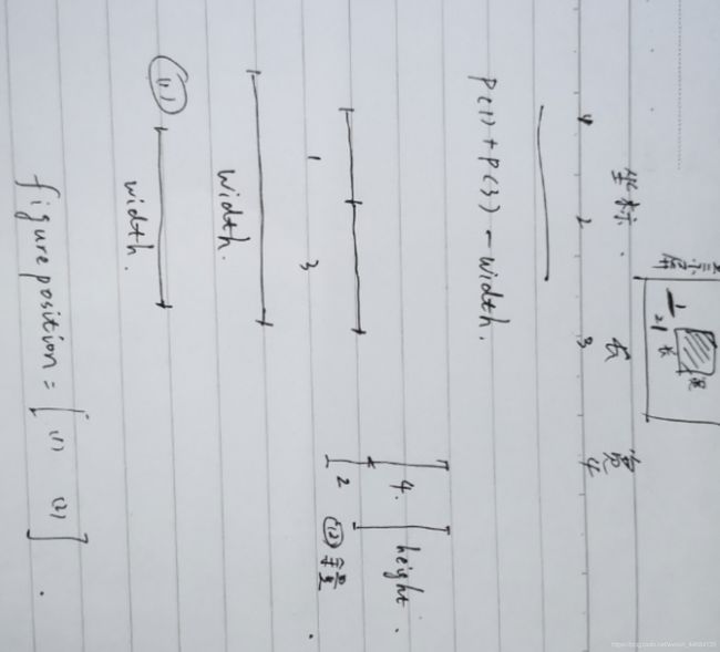
就是输入一个设定的width和height,返回一个figurePosition
也就是可以自定义figure框的位置
而输入的width和height与视频的宽度和高度有关
height+toolBarSize, width*2
一直到这一句就规定了figure窗口位置
f = figure(‘Position’, figurePosition, ‘Name’, ‘Forward Collision Warning With Tracking Example’);
③**axes:**创建笛卡尔坐标系
hVideoAxes = axes(f, ‘Units’, ‘Normal’, ‘Position’, [0.01 0.01 0.49 0.88]);
f为你这个figure框的句柄 绘图仪是为容器
units为位置单位 normal是采取归一化 根据容器进行归一化,容器通常是图窗或面板。容器的左下角映射到 (0,0),右上角映射到 (1,1)。
但是根据官方解释应该用normalized,估计是2018-2019版本问题
就是设置axes的位置,左下宽高,单位是和整个figure宽高的比例
四个数依次是坐标左下角起点坐标和长度,宽度。即[left bottom width height]
④然后有个函数 Create Video Objects for the Demo
videoDisplayHandle = createFCWDemoVideoDisplay(frame, hVideoAxes);
函数function:
function videoFrame = createFCWDemoVideoDisplay(frame, hVideoAxes)
% Initialize Video I/O
% Create objects for reading a video from a file and playing the video.

% Create a video player and display the first frame
videoFrame = imshow(frame, [], 'Parent', hVideoAxes);
h = title('Recorded Video');
set(h, 'Position', [320.5, -10, 0])
end
imshow用法

就是把视频显示在已经设定好的hVideoAxes父级坐标区域
[]表示灰度图像显示范围不加以限制
imshow的返回值为imshow的图像对象 也就是videoFrame
也就是与 videoDisplayHandle有关
⑤之后再设置鸟瞰图的位置 用同样的方法
先设置坐标系axes
用函数helperCreateFCWDemoBirdsEyePlot
bepPlotters = helperCreateFCWDemoBirdsEyePlot(sensorConfigurationFileName, bepAxes);
以此创建鸟瞰图图像对象 函数function:
function bepPlotters = helperCreateFCWDemoBirdsEyePlot(sensorConfigurationFile, bepAxes)
%helperCreateFCWDemoBirdsEyePlot   Prepare Birds-Eye-Plot Display in the
%Sensor Fusion and Forward Collision Warning Demo
%
%   This is an example helper function and is subject to change in future
%   releases.
%
% Creates a birdsEyePlot object and returns a struct of birdsEyePlotter
% objects. The birdsEyePlot is shown on the right half of the display.
%
% A birdsEyePlot is a plot that is configured to use the ego-centric car
% coordinate system, where the x-axis is pointed upwards, in front of the
% car, and the y-axis is pointed to the left.
%
% To create a birdsyEyePlot the following steps are performed:
%
% # Read sensor positions and coverage areas from |sensorConfigurationFile|
% # Create a birdsEyePlot in the defined axes. If none are defined, they
% will be created.
% # Create coverage area plotters for the vision and radar sensors.
% # Use the coverage area plotters to plot the sensor coverages.
% # Create detection plotters for each sensor.
% # Create track plotter for all the tracks.
% # Create track plotter for the most important object (MIO).
% # Create lane boundary plotter.

%   Copyright 2016 The MathWorks, Inc.

% If no axes are specified, they will be created by bird's-eye plot
if nargin == 1
    bepAxes = [];
end

% Read the sensor configuration file
load(sensorConfigurationFile, 'sensorParams');

%Create the birds-eye plot object
BEP = birdsEyePlot('Parent',bepAxes,'XLimits',[0 90],'YLimits',[-35 35]);

%Create the sensor coverage areas (vision is first, then two radars)
cap(1) = coverageAreaPlotter(BEP,'FaceColor','blue','EdgeColor','blue');
cap(2) = coverageAreaPlotter(BEP,'FaceColor','red','EdgeColor','red');
cap(3) = coverageAreaPlotter(BEP,'FaceColor','red','EdgeColor','red');

% plot the sensor coverage areas
for i = 1:3
    plotCoverageArea(cap(i), [sensorParams(i).X, sensorParams(i).Y],...
        sensorParams(i).Range, sensorParams(i).YawAngle, sensorParams(i).FoV);
end

% create a vision detection plotter put it in a struct for future use
bepPlotters.Vision = detectionPlotter(BEP, 'DisplayName','vision detection', ...
    'MarkerEdgeColor','blue', 'Marker','^');

% we'll combine all radar detctions into one entry and store it
% for later update
bepPlotters.Radar = detectionPlotter(BEP, 'DisplayName','radar detection', ...
    'MarkerEdgeColor','red');

% Show last 10 track updates
bepPlotters.Track = trackPlotter(BEP, 'DisplayName','tracked object', ...
    'HistoryDepth',10);

% Allow for a most important object
bepPlotters.MIO = trackPlotter(BEP, 'DisplayName','most important object', ...
    'MarkerFaceColor','black');

% Lane boundaries
bepPlotters.LaneBoundary = laneBoundaryPlotter(BEP, ...
    'DisplayName','lane boundaries', 'Color',[.9 .9 0]);

% Add title
title('Birds-Eye Plot')

% Lock the legend for speedup
set(BEP.Parent.Legend, 'AutoUpdate', 'off');
end
7.5日更新 详解鸟瞰图函数
要对这个函数输入传感器配置信息和为鸟瞰图设置的坐标系
首先 nargin用来判断输入变量的个数
如果输入变量为1个,也就是说只输入传感器配置文件未提前设定坐标系的话,那么将坐标系设为空(不太懂?)
7.12更新:也就是未输入坐标系的话鸟瞰图单独弹出来 不在figure里面
然后加载load(sensorConfigurationFile, ‘sensorParams’);也就是加载配置文件中的变量sensorParams传感器参数
然后创建鸟瞰图对象(创建覆盖绘图仪)
BEP = birdsEyePlot(‘Parent’,bepAxes,‘XLimits’,[0 90],‘YLimits’,[-35 35]);
https://ww2.mathworks.cn/help/driving/ref/birdseyeplot.html
bepAxes可能为[]
父容器为设定好的坐标系,limits为鸟瞰图的范围 最后绘制出一个框 如下图

紧接着创建传感器覆盖区域(视觉是第一个,然后是两个雷达)
cap(1) = coverageAreaPlotter(BEP,‘FaceColor’,‘blue’,‘EdgeColor’,‘blue’);
cap(2) = coverageAreaPlotter(BEP,‘FaceColor’,‘red’,‘EdgeColor’,‘red’);
cap(3) = coverageAreaPlotter(BEP,‘FaceColor’,‘red’,‘EdgeColor’,‘red’);
coverageAreaPlotter创建一个对象,用于配置鸟瞰图上传感器覆盖区域的显示。该对象存储在输入对象的属性中,分别是覆盖区域的颜色和边界的颜色
下面是分配三个cap进行绘图 1表示视觉传感器,2、3表示毫米波雷达
% plot the sensor coverage areas
for i = 1:3
plotCoverageArea(cap(i), [sensorParams(i).X, sensorParams(i).Y],…
sensorParams(i).Range, sensorParams(i).YawAngle, sensorParams(i).FoV);
end
plotCoverageArea在鸟瞰图上显示自我车辆传感器的覆盖区域。指定(输入)传感器的位置,范围,方向角(与x轴之间的夹角,注意这里的x轴和直观的区别)和视野(FoV,如35度视野)。覆盖区域绘图仪caPlotter与birdsEyePlot对象相关联并配置传感器覆盖区域的显示。
自此绘制出鸟瞰图边框和传感器覆盖范围图
接下来
创建一个视觉检测绘图仪将它放在一个结构中以备将来使用
bepPlotters.Vision = detectionPlotter(BEP, ‘DisplayName’,‘vision detection’, …
‘MarkerEdgeColor’,‘blue’, ‘Marker’,’^’);
bepPlotters为图形对象
这种格式一上来就吓坏了 为什么连bepPlotters还没有定义 就直接开始为他的属性定义了!
其实是
https://ww2.mathworks.cn/help/driving/ref/birdseyeplot.html?s_tid=doc_ta
解释的由bep = birdsEyePlot(Name,Value)创建的绘图仪功能
detectionPlotter用于配置鸟瞰图上对象检测的显示
就是检测到的对象 用各种颜色形状的点表示 具体的对应为:
 注意两个点 都是在创建功能那个表格里面
% Lane boundaries
bepPlotters.LaneBoundary = laneBoundaryPlotter(BEP, ‘DisplayName’,‘lane boundaries’, ‘Color’,[.9 .9 0]);的时候写的是color
% Show last 10 track updates
bepPlotters.Track = trackPlotter(BEP, ‘DisplayName’,‘tracked object’, ‘HistoryDepth’,10);
https://ww2.mathworks.cn/help/driving/ref/birdseyeplot.trackplotter.html
trackPlotter显示前几步位置,显示的是前十步轨迹
(其实跟踪器的说法是在传感器融合和跟踪数据箱里面
https://ww2.mathworks.cn/help/fusion/ref/theaterplot.detectionplotter.html?s_tid=doc_ta,删除)
接下来是set(BEP.Parent.Legend, ‘AutoUpdate’, ‘off’);
https://blog.csdn.net/weixin_41554884/article/details/79913272
也就是在绘图仪上设置图例 关闭自动更新
https://blog.csdn.net/Reborn_Lee/article/details/82857626#在作图命令中(plot)给出图例标签;
(自动更新这里搞不太懂)7.14解释:

至此生成鸟瞰图函数解释完毕
由此创建了一个鸟瞰图并定义了他的位置
然后
load(‘FCWDemoMonoCameraSensor.mat’, ‘sensor’)
也就是从FCWDemoMonoCameraSensor.mat文件中读取变量sensor
文件包含了传感器的位置、mono捕获的图像信息
即加载单目摄像机对象以进行视频显示
videoReader.CurrentTime = 0;设定视频截取的起始时间 输入5则第一帧为5
至此helperCreateFCWDemoDisplay函数解读完毕
研究一下返回的四个值
[videoReader, videoDisplayHandle, bepPlotters, sensor]
①第一个是一个结构体
videoReader是VideoReader 的结果 返回一个结构体 有关视频的各种信息,但不包括画面本身像素
VideoReader - 该函数用于读取视频文件对象。
函数调用格式:
obj = VideoReader(filename)
obj = VideoReader(filename,Name,Value)
其中obj为结构体,包括如下成员:
Name - 视频文件名
Path - 视频文件路径
Duration - 视频的总时长(秒)
FrameRate - 视频帧速(帧/秒)
NumberOfFrames - 视频的总帧数
Height - 视频帧的高度
Width - 视频帧的宽度
BitsPerPixel - 视频帧每个像素的数据长度(比特)
VideoFormat - 视频的类型, 如 ‘RGB24’.
Tag - 视频对象的标识符,默认为空字符串’’
Type - 视频对象的类名,默认为’VideoReader’.
UserData - Generic field for data of any class that you want to add to the object. Default: []
如,视频的总帧数为numFrames = obj.NumberOfFrames;
②videoDisplayHandle
是createFCWDemoVideoDisplay返回的videoFrame
videoFrame = imshow(frame, [], ‘Parent’, hVideoAxes);它与imshow有关 imshow返回视频的一帧图像的像素矩阵(0-255或0-1)和显示他的位置
③bepPlotters
返回鸟瞰图绘图仪(包含各种配置信息)及其位置
④sensor
返回传感器变量 由monocamera那个文件决定的
————————————————————————————————————————————
接下来 读取录制的检测文件
% Read the recorded detections file
[visionObjects, radarObjects, inertialMeasurementUnit, laneReports, ...
    timeStep, numSteps] = readSensorRecordingsFile('01_city_c2s_fcw_10s_sensor.mat');
找到下面定义的函数readSensorRecordingsFile 要读传感器的记录数据
函数function:
%% Supporting Functions
%%%
% *readSensorRecordingsFile*
% Reads recorded sensor data from a file
function [visionObjects, radarObjects, inertialMeasurementUnit, laneReports, ...
    timeStep, numSteps] = readSensorRecordingsFile(sensorRecordingFileName)
% Read Sensor Recordings
% The |ReadDetectionsFile| function reads the recorded sensor data file.
% The recorded data is a single structure that is divided into the
% following substructures:
%
% # |inertialMeasurementUnit|, a struct array with fields: timeStamp,
%   velocity, and yawRate. Each element of the array corresponds to a
%   different timestep.
% # |laneReports|, a struct array with fields: left and right. Each element
%   of the array corresponds to a different timestep.
%   Both left and right are structures with fields: isValid, confidence,
%   boundaryType, offset, headingAngle, and curvature.
% # |radarObjects|, a struct array with fields: timeStamp (see below),
%   numObjects (integer) and object (struct). Each element of the array
%   corresponds to a different timestep.
%   |object| is a struct array, where each element is a separate object,
%   with the fields: id, status, position(x;y;z), velocity(vx,vy,vz),
%   amplitude, and rangeMode.
%   Note: z is always constant and vz=0.
% # |visionObjects|, a struct array with fields: timeStamp (see below),
%   numObjects (integer) and object (struct). Each element of the array
%   corresponds to a different timestep.
%   |object| is a struct array, where each element is a separate object,
%   with the fields: id, classification, position (x;y;z),
%   velocity(vx;vy;vz), size(dx;dy;dz). Note: z=vy=vz=dx=dz=0
%
% The timeStamp for recorded vision and radar objects is a uint64 variable
% holding microseconds since the Unix epoch. Timestamps are recorded about
% 50 milliseconds apart. There is a complete synchronization between the
% recordings of vision and radar detections, therefore the timestamps are
% not used in further calculations.

A = load(sensorRecordingFileName);
visionObjects = A.vision;
radarObjects = A.radar;
laneReports = A.lane;
inertialMeasurementUnit = A.inertialMeasurementUnit;

timeStep = 0.05;                 % Data is provided every 50 milliseconds
numSteps = numel(visionObjects); % Number of recorded timesteps
end
开始详细解读readSensorRecordingsFile
A = load(sensorRecordingFileName);加载传感器记录文件,记录了传感器的获取信息,句柄为A
也就是文件01_city_c2s_fcw_10s_sensor.mat
文件里包含了几个结构:
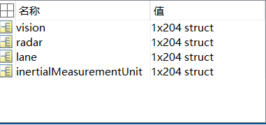
visionObjects = A.vision;
radarObjects = A.radar;
laneReports = A.lane;
inertialMeasurementUnit = A.inertialMeasurementUnit;
取出各个传感器的测量结果
看了.mat文件的详细内容 研究一下时间戳timestamp添加链接描述:
经过时间戳转换函数
function [ date ] = ConvertDate( x )
%将unix时间戳转换为标准时间
% date = datestr(1461634690/86400 + datenum(1970,1,1),31);
date = datestr((x-360024+83600)/86400 + datenum(1970,1,1),31);
end
可以知道传感器检测文件里的timestamp如1461634690179938去掉后六位带入进去才是对的
也就是说去掉后六位才是秒,那么现在是微秒
观察:
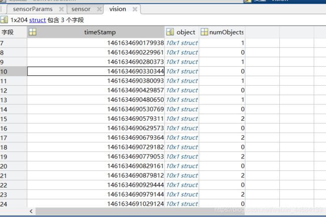
发现按照以上分析确实是每次输出检测结果的间隔为50ms
然后令
timeStep = 0.05; % Data is provided every 50 milliseconds
numSteps = numel(visionObjects); % Number of recorded timesteps
numSteps是204个 204×0.05=10.2s
10.2是总共10.2s的视频对象(检测时间)
先看看以后哪里用到了timeStep和numSteps
都是在循环里面用到的 之后再说
总而言之,返回的是
①inertialMeasurementUnit
惯性测量单元
IMU(惯性测量单元,一个IMU包含了三个单轴的加速度计和三个单轴的陀螺),每秒20次报告自我车辆的速度和转弯率。
因此返回了它记录的数据 每个时刻的都不一样
Each element of the array corresponds to a different timestep
②laneReports车道报告
③雷达检测对象
④视觉检测对象
⑤timeStep
每50微秒提供一次数据 每一次大一统时间戳加0.05秒
⑥numSteps
numSteps = numel(visionObjects)
numel是返回数组中元素个数
numSteps = numel(visionObjects); % Number of recorded timesteps
表示记了204次50微秒 获得了204次的vision结果
返回了各项传感器记录数据以及两个step
至此readSensorRecordingsFile解读完毕
————————————————————————————————————————————
接下来::
计算初始自我车道。 如果记录的车道信息是无效的,将车道边界定义为汽车两侧半个车道距离的直线
% An initial ego lane is calculated. If the recorded lane information is
% invalid, define the lane boundaries as straight lines half a lane
% distance on each side of the car
laneWidth = 3.6; % meters
egoLane = struct('left', [0 0 laneWidth/2], 'right', [0 0 -laneWidth/2]);
目的是在检测不到车道的时候强行加一个自我车道?
创建结构体 直接用sruct命令,‘left’为结构体的名称,后面的是结构体的内容
然后
准备一些变量
% Prepare some time variables
time = 0;           % Time since the beginning of the recording
currentStep = 0;    % Current timestep
snapTime = 9.3;     % The time to capture a snapshot of the display捕获显示快照的时间
time是用来+timeStep的
currentStep 是用来+1直到numsteps
snapTime捕获显示快照的时间暂时存疑
然后初始化跟踪器
% Initialize the tracker
[tracker, positionSelector, velocitySelector] = setupTracker();
不需要输入变量 直接进行返回
那么此函数要看下边详解
setupTracker()函数解释
函数function:
 function [tracker, positionSelector, velocitySelector] = setupTracker()
        tracker = multiObjectTracker(...
            'FilterInitializationFcn', @initConstantAccelerationFilter, ...
            'AssignmentThreshold', 35, 'ConfirmationParameters', [2 3], ...
            'NumCoastingUpdates', 5);

        % The State vector is:
        %   In constant velocity:     State = [x;vx;y;vy]
        %   In constant acceleration: State = [x;vx;ax;y;vy;ay]

        % Define which part of the State is the position. For example:
        %   In constant velocity:     [x;y] = [1 0 0 0; 0 0 1 0] * State
        %   In constant acceleration: [x;y] = [1 0 0 0 0 0; 0 0 0 1 0 0] * State
        positionSelector = [1 0 0 0 0 0; 0 0 0 1 0 0];

        % Define which part of the State is the velocity. For example:
        %   In constant velocity:     [x;y] = [0 1 0 0; 0 0 0 1] * State
        %   In constant acceleration: [x;y] = [0 1 0 0 0 0; 0 0 0 0 1 0] * State
        velocitySelector = [0 1 0 0 0 0; 0 0 0 0 1 0];
    end
里面套了一个multiObjectTracker函数 需要回到此网站最开始点击多目标跟踪
对象检测是在单个帧中定位感兴趣对象的过程。跟踪将对象的检测跨多个帧关联
https://ww2.mathworks.cn/help/driving/ref/multiobjecttracker-system-object.html?searchHighlight=multiObjectTracker&s_tid=doc_srchtitle
这个是multiObjectTracker的详细解释
函数multiObjectTracker解释
函数function:
%% Create the Multi-Object Tracker
% The |multiObjectTracker| tracks the objects around the ego vehicle based
% on the object lists reported by the vision and radar sensors. By fusing
% information from both sensors, the probability of a false collision
% warning is reduced.
%
% The |setupTracker| function returns the |multiObjectTracker|.
% When creating a |multiObjectTracker|, consider the following:
%
% # |FilterInitializationFcn|: The likely motion and measurement models.
%   In this case, the objects are expected to have a constant acceleration
%   motion. Although you can configure a linear Kalman filter for this
%   model, |initConstantAccelerationFilter| configures an extended Kalman
%   filter. See the 'Define a Kalman filter' section.
% # |AssignmentThreshold|: How far detections can fall from tracks.
%   The default value for this parameter is 30. If there are detections
%   that are not assigned to tracks, but should be, increase this value. If
%   there are detections that get assigned to tracks that are too far,
%   decrease this value. This example uses 35.
% # |NumCoastingUpdates|: How many times a track is coasted before deletion.
%   Coasting is a term used for updating the track without an assigned
%   detection (predicting).
%   The default value for this parameter is 5. In this case, the tracker is
%   called 20 times a second and there are two sensors, so there is no need
%   to modify the default.
% # |ConfirmationParameters|: The parameters for confirming a track.
%   A new track is initialized with every unassigned detection. Some of
%   these detections might be false, so all the tracks are initialized as
%   |'Tentative'|. To confirm a track, it has to be detected at least _M_
%   times in _N_ tracker updates. The choice of _M_ and _N_ depends on the
%   visibility of the objects. This example uses the default of 2
%   detections out of 3 updates.
%
% The outputs of |setupTracker| are:
%
% * |tracker| - The |multiObjectTracker| that is configured for this case.
% * |positionSelector| - A matrix that specifies which elements of the
%   State vector are the position: |position = positionSelector * State|
% * |velocitySelector| - A matrix that specifies which elements of the
%   State vector are the velocity: |velocity = velocitySelector * State|
    function [tracker, positionSelector, velocitySelector] = setupTracker()
        tracker = multiObjectTracker(...
            'FilterInitializationFcn', @initConstantAccelerationFilter, ...
            'AssignmentThreshold', 35, 'ConfirmationParameters', [2 3], ...
            'NumCoastingUpdates', 5);

        % The State vector is:
        %   In constant velocity:     State = [x;vx;y;vy]
        %   In constant acceleration: State = [x;vx;ax;y;vy;ay]

        % Define which part of the State is the position. For example:
        %   In constant velocity:     [x;y] = [1 0 0 0; 0 0 1 0] * State
        %   In constant acceleration: [x;y] = [1 0 0 0 0 0; 0 0 0 1 0 0] * State
        positionSelector = [1 0 0 0 0 0; 0 0 0 1 0 0];

        % Define which part of the State is the velocity. For example:
        %   In constant velocity:     [x;y] = [0 1 0 0; 0 0 0 1] * State
        %   In constant acceleration: [x;y] = [0 1 0 0 0 0; 0 0 0 0 1 0] * State
        velocitySelector = [0 1 0 0 0 0; 0 0 0 0 1 0];
    end
该 多对象跟踪系统对象初始化™,确认,预测,修正和删除移动物体的轨道。多对象跟踪器的输入是由对象,对象或对象生成的检测报告(对检测结果进行分析进而跟踪)。多对象跟踪器接受来自多个传感器的检测,并使用全局最近邻居(GNN)标准将它们分配给轨道。每个检测都分配给一个单独的轨道。如果无法将检测分配给任何轨道,则基于属性,跟踪器会创建新轨道。轨道以结构数组的形式返回
确认轨道后,多对象跟踪器会将该轨道视为物理实体对象。如果未在可指定数量的更新中将检测添加到轨道,则会删除该轨道。
跟踪器还使用卡尔曼滤波器估计每个轨道的状态向量和状态向量协方差矩阵。这些状态向量用于预测每个帧中的轨道位置,并确定每个检测被分配给每个轨道的可能性。(记住跟踪器这里用到了卡尔曼滤波,用来消减噪声,提高轨道的精确性)
若为tracker = multiObjectTracker 使用默认属性值创建 System对象。
这里有个 System对象的概念
https://ww2.mathworks.cn/help/matlab/matlab_prog/what-are-system-objects.html
System object 非常适用于分段处理大型数据流的迭代计算,这种处理流化数据的功能具有不必在内存中保存大量数据的优点。采用流化数据,您还可以使用可高效利用循环的简化程序

原文的 设置属性值创建System对象****(就是上面的每个框图)
tracker = multiObjectTracker(…
‘FilterInitializationFcn’, @initConstantAccelerationFilter, …
‘AssignmentThreshold’, 35, ‘ConfirmationParameters’, [2 3], …
‘NumCoastingUpdates’, 5);
7.6日更新详细解释
①**'FilterInitializationFcn’卡尔曼滤波器初始化函数**

这里是自己定义的函数 初始化恒加速度的卡尔曼滤波器 即函数initConstantAccelerationFilter
在multiObjectTracker上一节中所定义使用在本节创建卡尔曼滤波器(线性,扩展或无迹)中定义的滤波器初始化函数。然后该过滤器用于跟踪自我车辆周围的每个物体。
initConstantAccelerationFilter函数解析
先复习卡尔曼滤波:https://blog.csdn.net/Yujianzqmx/article/details/79178292
函数function:
 Define a Kalman Filter
% The |multiObjectTracker| defined in the previous section uses the filter
% initialization function defined in this section to create a Kalman filter
% (linear, extended, or unscented). This filter is then used for tracking
% each object around the ego vehicle.
function filter = initConstantAccelerationFilter(detection)
% This function shows how to configure a constant acceleration filter. The
% input is an objectDetection and the output is a tracking filter.
% For clarity, this function shows how to configure a trackingKF,
% trackingEKF, or trackingUKF for constant acceleration.
%
% Steps for creating a filter:
%   1. Define the motion model and state
%   2. Define the process noise
%   3. Define the measurement model
%   4. Initialize the state vector based on the measurement
%   5. Initialize the state covariance based on the measurement noise
%   6. Create the correct filter

    % Step 1: Define the motion model and state
    % This example uses a constant acceleration model, so:
    STF = @constacc;     % State-transition function, for EKF and UKF
    STFJ = @constaccjac; % State-transition function Jacobian, only for EKF
    % The motion model implies that the state is [x;vx;ax;y;vy;ay]
    % You can also use constvel and constveljac to set up a constant
    % velocity model, constturn and constturnjac to set up a constant turn
    % rate model, or write your own models.

    % Step 2: Define the process noise
    dt = 0.05; % Known timestep size
    sigma = 1; % Magnitude of the unknown acceleration change rate
    % The process noise along one dimension
    Q1d = [dt^4/4, dt^3/2, dt^2/2; dt^3/2, dt^2, dt; dt^2/2, dt, 1] * sigma^2;
    Q = blkdiag(Q1d, Q1d); % 2-D process noise

    % Step 3: Define the measurement model
    MF = @fcwmeas;       % Measurement function, for EKF and UKF
    MJF = @fcwmeasjac;   % Measurement Jacobian function, only for EKF

    % Step 4: Initialize a state vector based on the measurement
    % The sensors measure [x;vx;y;vy] and the constant acceleration model's
    % state is [x;vx;ax;y;vy;ay], so the third and sixth elements of the
    % state vector are initialized to zero.
    state = [detection.Measurement(1); detection.Measurement(2); 0; detection.Measurement(3); detection.Measurement(4); 0];

    % Step 5: Initialize the state covariance based on the measurement
    % noise. The parts of the state that are not directly measured are
    % assigned a large measurement noise value to account for that.
    L = 100; % A large number relative to the measurement noise
    stateCov = blkdiag(detection.MeasurementNoise(1:2,1:2), L, detection.MeasurementNoise(3:4,3:4), L);

    % Step 6: Create the correct filter.
    % Use 'KF' for trackingKF, 'EKF' for trackingEKF, or 'UKF' for trackingUKF
    FilterType = 'EKF';

    % Creating the filter:
    switch FilterType
        case 'EKF'
            filter = trackingEKF(STF, MF, state,...
                'StateCovariance', stateCov, ...
                'MeasurementNoise', detection.MeasurementNoise(1:4,1:4), ...
                'StateTransitionJacobianFcn', STFJ, ...
                'MeasurementJacobianFcn', MJF, ...
                'ProcessNoise', Q ...
                );
        case 'UKF'
            filter = trackingUKF(STF, MF, state, ...
                'StateCovariance', stateCov, ...
                'MeasurementNoise', detection.MeasurementNoise(1:4,1:4), ...
                'Alpha', 1e-1, ...
                'ProcessNoise', Q ...
                );
        case 'KF' % The ConstantAcceleration model is linear and KF can be used
            % Define the measurement model: measurement = H * state
            % In this case:
            %   measurement = [x;vx;y;vy] = H * [x;vx;ax;y;vy;ay]
            % So, H = [1 0 0 0 0 0; 0 1 0 0 0 0; 0 0 0 1 0 0; 0 0 0 0 1 0]
            %
            % Note that ProcessNoise is automatically calculated by the
            % ConstantAcceleration motion model
            H = [1 0 0 0 0 0; 0 1 0 0 0 0; 0 0 0 1 0 0; 0 0 0 0 1 0];
            filter = trackingKF('MotionModel', '2D Constant Acceleration', ...
                'MeasurementModel', H, 'State', state, ...
                'MeasurementNoise', detection.MeasurementNoise(1:4,1:4), ...
                'StateCovariance', stateCov);
    end
end
如何配置恒定加速度过滤器
detection变量在右边的工作区里面有
翻译一下有五个步骤:
创建过滤器的步骤:
%1。定义运动模型和状态
%2。定义过程噪音
%3。定义测量模型
%4。根据测量结果初始化状态向量
%5。根据测量噪声初始化状态协方差
%6。创建正确的过滤器
步骤1:定义运动模型和状态
本示例采用恒加速度模型 故
STF = @constacc; % State-transition function, for EKF and UKF
STFJ = @constaccjac; % State-transition function Jacobian, only for EKF
那么什么是EKF\UKF
都是为了处理非线性问题的(扩展、无迹)
https://ww2.mathworks.cn/help/driving/ref/constaccjac.html
创建了状态估计函数的句柄 函数目的是以此时刻预测下一时刻
运动模型意味着状态是[x; vx; ax; y; vy; ay]
步骤2:定义过程噪音
dt = 0.05; % Known timestep size
sigma = 1; % Magnitude of the unknown acceleration change rate
% The process noise along one dimension
Q1d = [dt^4/4, dt^3/2, dt^2/2; dt^3/2, dt^2, dt; dt^2/2, dt, 1] * sigma^2;
Q = blkdiag(Q1d, Q1d); % 2-D process noise
0.05s是之前有过的检测间隔 因此这里就是0.05s的预测间隔
恒加速度 故加速度变化率为1
然后是预测过程(先验估计)的过程噪声的确定
Q1d 为什么是这样算的不明白
但Q1d是3×3
运动模型是6×1 故A为6×6,噪声应该为6×6
blkdiag是生成分块对角矩阵,两个Q1d组成了6×6的分块对角矩阵
步骤3:定义测量模型
MF = @fcwmeas; % Measurement function, for EKF and UKF
MJF = @fcwmeasjac; % Measurement Jacobian function, only for EKF
但是上边两个测量模型函数在matlab官网上并没有解释 发现其实是自己定义的
函数function:
function measurement = fcwmeas(state, sensorID)
% The example measurements depend on the sensor type, which is reported by
% the MeasurementParameters property of the objectDetection. The following
% two sensorID values are used:
%   sensorID=1: video objects, the measurement is [x;vx;y].
%   sensorID=2: radar objects, the measurement is [x;vx;y;vy].
% The state is:
%   Constant velocity       state = [x;vx;y;vy]
%   Constant turn           state = [x;vx;y;vy;omega]
%   Constant acceleration   state = [x;vx;ax;y;vy;ay]

    if numel(state) < 6 % Constant turn or constant velocity
        switch sensorID
            case 1 % video
                measurement = [state(1:3); 0];
            case 2 % radar
                measurement = state(1:4);
        end
    else % Constant acceleration
        switch sensorID
            case 1 % video
                measurement = [state(1:2); state(4); 0];
            case 2 % radar
                measurement = [state(1:2); state(4:5)];
        end
    end
end
%%%
% *fcwmeasjac*
% The Jacobian of the measurement function used in this forward collision
% warning example
function jacobian = fcwmeasjac(state, sensorID)
% The example measurements depend on the sensor type, which is reported by
% the MeasurementParameters property of the objectDetection. We choose
% sensorID=1 for video objects and sensorID=2 for radar objects.  The
% following two sensorID values are used:
%   sensorID=1: video objects, the measurement is [x;vx;y].
%   sensorID=2: radar objects, the measurement is [x;vx;y;vy].
% The state is:
%   Constant velocity       state = [x;vx;y;vy]
%   Constant turn           state = [x;vx;y;vy;omega]
%   Constant acceleration   state = [x;vx;ax;y;vy;ay]

    numStates = numel(state);
    jacobian = zeros(4, numStates);

    if numel(state) < 6 % Constant turn or constant velocity
        switch sensorID
            case 1 % video
                jacobian(1,1) = 1;
                jacobian(2,2) = 1;
                jacobian(3,3) = 1;
            case 2 % radar
                jacobian(1,1) = 1;
                jacobian(2,2) = 1;
                jacobian(3,3) = 1;
                jacobian(4,4) = 1;
        end
    else % Constant acceleration
        switch sensorID
            case 1 % video
                jacobian(1,1) = 1;
                jacobian(2,2) = 1;
                jacobian(3,4) = 1;
            case 2 % radar
                jacobian(1,1) = 1;
                jacobian(2,2) = 1;
                jacobian(3,4) = 1;
                jacobian(4,5) = 1;
        end
    end
end
翻译为:示例测量取决于传感器类型,该类型由objectDetection的MeasurementParameters属性报告。
但是objectDetection这个检测报告是如何生成并且已经存在的 存疑
我们为视频对象选择sensorID = 1,为雷达对象选择sensorID = 2。 使用以下两个sensorID值:
%sensorID = 1:视频对象,测量值为[x; vx; y]。
%sensorID = 2:雷达物体,测量值为[x; vx; y; vy]。
%状态是:(也就是卡尔曼滤波过程中的滤波对象)
%恒速状态= [x; vx; y; vy]
%常转状态= [x; vx; y; vy; omega]
%恒定加速状态= [x; vx; ax; y; vy; ay]
switch 的用法
代码理解较容易,但为什么是这样的测量值存疑
自己理解一波:
只看恒加速度模型:
恒定加速状态state= [x; vx; ax; y; vy; ay]
else % Constant acceleration
switch sensorID
case 1 % video
measurement = [state(1:2); state(4); 0];
case 2 % radar
measurement = [state(1:2); state(4:5)];
measurement估计是测量结果
% sensorID=1: video objects, the measurement is [x;vx;y].
% sensorID=2: radar objects, the measurement is [x;vx;y;vy].
为什么摄像头检测不了y向加速度
雷达主要进行测速和测距,故没有加速度
故case1的measurement = [x;vx;y;0];
故case2的measurement = [x;vx;y;vy];
H为传递函数 这里很显然是1 即不考虑
再看看雅可比的:也是只看恒加速度的
numStates = numel(state); 即是6
jacobian = zeros(4, numStates); 即雅可比矩阵是4×6
else % Constant acceleration
switch sensorID
case 1 % video
jacobian(1,1) = 1;
jacobian(2,2) = 1;
jacobian(3,4) = 1;
case 2 % radar
jacobian(1,1) = 1;
jacobian(2,2) = 1;
jacobian(3,4) = 1;
jacobian(4,5) = 1;
P是协方差矩阵 比如初始后验估计为六元素向量,那么初始协方差矩阵为6×6
具体带雅可比的怎么用见https://www.cnblogs.com/yrm1160029237/p/10161663.html
测量值就是真实状态值(没有传递函数)

4个f: f代表的是从上一个状态估计这一个状态时的函数 因为是[x;vx;y;vy]. 四个状态量,故有四个f
这里由于是测量模型,雅可比矩阵肯定是H的雅可比 测量方程有四种H 因此有四行 分别代表不同的转移函数,列有六列 代表有六个状态变量 也就是真正带入卡尔曼滤波算法的是这六个状态组成的向量

继续
步骤4、根据测量结果初始化状态向量
% The sensors measure [x;vx;y;vy] and the constant acceleration model’s
% state is [x;vx;ax;y;vy;ay], so the third and sixth elements of the
% state vector are initialized to zero.
state = [detection.Measurement(1); detection.Measurement(2); 0; detection.Measurement(3); detection.Measurement(4); 0];
步骤5、根据测量噪声初始化状态协方差
% Step 5: Initialize the state covariance based on the measurement
% noise. The parts of the state that are not directly measured are
% assigned a large measurement noise value to account for that.
L = 100; % A large number relative to the measurement noise
stateCov = blkdiag(detection.MeasurementNoise(1:2,1:2), L, detection.MeasurementNoise(3:4,3:4), L);
初始化状态协方差6元素,未被直接测量的状态部分(加速度值)被分配了大的测量噪声值
blkdiag创建分块对角矩阵
detection是右边变量 (怎么来的存疑)
步骤6、创建正确的过滤器
% Step 6: Create the correct filter.
% Use ‘KF’ for trackingKF, ‘EKF’ for trackingEKF, or ‘UKF’ for trackingUKF
EKF是扩展卡尔曼滤波 UKF是无迹卡尔曼滤波
FilterType = ‘EKF’;这里采用扩展卡尔曼滤波
然后
% Creating the filter:
switch FilterType
case ‘EKF’
filter = trackingEKF(STF, MF, state,…
‘StateCovariance’, stateCov, …
‘MeasurementNoise’, detection.MeasurementNoise(1:4,1:4), …
‘StateTransitionJacobianFcn’, STFJ, …
‘MeasurementJacobianFcn’, MJF, …
‘ProcessNoise’, Q …
);
case ‘UKF’
filter = trackingUKF(STF, MF, state, …
‘StateCovariance’, stateCov, …
‘MeasurementNoise’, detection.MeasurementNoise(1:4,1:4), …
‘Alpha’, 1e-1, …
‘ProcessNoise’, Q …
);
case ‘KF’ % The ConstantAcceleration model is linear and KF can be used
% Define the measurement model: measurement = H * state
% In this case:
% measurement = [x;vx;y;vy] = H * [x;vx;ax;y;vy;ay]
% So, H = [1 0 0 0 0 0; 0 1 0 0 0 0; 0 0 0 1 0 0; 0 0 0 0 1 0]
%
% Note that ProcessNoise is automatically calculated by the
% ConstantAcceleration motion model
H = [1 0 0 0 0 0; 0 1 0 0 0 0; 0 0 0 1 0 0; 0 0 0 0 1 0];
filter = trackingKF(‘MotionModel’, ‘2D Constant Acceleration’, …
‘MeasurementModel’, H, ‘State’, state, …
‘MeasurementNoise’, detection.MeasurementNoise(1:4,1:4), …
‘StateCovariance’, stateCov);
end
end
Q为状态方程噪声(过程噪声),发现最后一部分KF不需要定义过程噪声Q,是因为此2D Constant Accelerationmatlab会自动计算
至此卡尔曼滤波器initConstantAccelerationFilter函数讲解完毕
继续讲解函数multiObjectTracker
tracker = multiObjectTracker(…
‘FilterInitializationFcn’, @initConstantAccelerationFilter, …
‘AssignmentThreshold’, 35, ‘ConfirmationParameters’, [2 3], …
‘NumCoastingUpdates’, 5);
②AssignmentThreshold检测分配阈值,指定为正实数标量。要为轨道分配检测,检测到轨道的标准化距离必须小于分配阈值。如果某些检测仍未分配给您希望分配给它们的轨道,请增加阈值。如果将某些检测分配给错误的曲目,请降低阈值。
③ ‘ConfirmationParameters’, [2 3]
轨道创建的确认参数,指定为正增长整数的双元素向量[M N],其中M小于N。当在轨道初始化之后的前N次更新期间至少M个检测被分配给轨道时,确认轨道。即前五次更新 有三次被分配给轨道 则其确认生成一个轨道
设置时M,请考虑传感器的物体检测概率。检测的概率取决于诸如遮挡或杂乱的因素。M当轨道无法确认时可以减少,或者M当为轨道分配太多错误检测时,可以增加轨道。
设置时N,请考虑在做出确认决定之前您希望跟踪器更新的次数。例如,如果跟踪器每0.05秒更新一次,并且您允许0.5秒做出确认决定,请进行设置N = 10。
之前决定的timestep=0.05s更新一次
例: [3 5]
④’NumCoastingUpdates’, 5
轨道删除的惯性阈值,指定为正整数。在一个或多个预测步骤之后没有检测到该确认的轨道时,轨道 滑行。如果滑行步数超过该滑行阈值,则对象删除该轨道。
继续这个大函数里的描述:
positionSelector = [1 0 0 0 0 0; 0 0 0 1 0 0];
与State相乘用以状态选择 选择位置(x,y)用。
velocitySelector = [0 1 0 0 0 0; 0 0 0 0 1 0];
与State相乘用以状态选择 选择速度(Vx,Vy)用。
至此,setupTracker()函数解释完毕
————————————————————————————————————————————
然后
while currentStep < numSteps && ishghandle(videoDisplayHandle)
    % Update scenario counters
    currentStep = currentStep + 1;
    time = time + timeStep;
numSteps=204
ishghandle(videoDisplayHandle)
由上面的分析知道
videoDisplayHandle是
②videoDisplayHandle
是createFCWDemoVideoDisplay返回的videoFrame
videoFrame = imshow(frame, [], ‘Parent’, hVideoAxes);它与imshow有关 imshow返回像素矩阵(0-255或0-1)和显示他的位置
因此为一帧图形信息,若为有效图形 则ishghandle返回逻辑1
timeStep = 0.05;
然后
    % Process the sensor detections as objectDetection inputs to the tracker
    [detections, laneBoundaries, egoLane] = processDetections(...
        visionObjects(currentStep), radarObjects(currentStep), ...
        inertialMeasurementUnit(currentStep), laneReports(currentStep), ...
        egoLane, time);
% Process the sensor detections as objectDetection inputs to the tracker
是将传感器的检测到的检测对象输入到跟踪器准备进行跟踪
processDetections函数解析
输入为:visionFrame, radarFrame, IMUFrame, laneFrame, egoLane, time
visionFrame即为视觉传感器获取的一帧图像
实际输入为:visionObjects(currentStep), radarObjects(currentStep), …
inertialMeasurementUnit(currentStep), laneReports(currentStep), …
egoLane, time
函数function:
function [detections,laneBoundaries, egoLane] = processDetections...
            (visionFrame, radarFrame, IMUFrame, laneFrame, egoLane, time)
        % Inputs:
        %   visionFrame - objects reported by the vision sensor for this time frame
        %   radarFrame  - objects reported by the radar sensor for this time frame
        %   IMUFrame    - inertial measurement unit data for this time frame
        %   laneFrame   - lane reports for this time frame
        %   egoLane     - the estimated ego lane
        %   time        - the time corresponding to the time frame

        % Remove clutter radar objects
        [laneBoundaries, egoLane] = processLanes(laneFrame, egoLane);
        realRadarObjects = findNonClutterRadarObjects(radarFrame.object,...
            radarFrame.numObjects, IMUFrame.velocity, laneBoundaries);

        % Return an empty list if no objects are reported

        % Counting the total number of objects
        detections = {};
        if (visionFrame.numObjects + numel(realRadarObjects)) == 0
            return;
        end

        % Process the remaining radar objects
        detections = processRadar(detections, realRadarObjects, time);

        % Process video objects
        detections = processVideo(detections, visionFrame, time);
    end
必须先处理和格式化记录的信息,然后才能由跟踪器使用,包含以下两个步骤:
**①过滤掉不必要的雷达杂波检测。 **雷达报告许多与固定物体相对应的物体,****包括:护栏,道路中间,交通标志等。如果在跟踪中使用这些检测,它们会在道路边缘产生固定物体的虚假轨迹, 因此必须在调用跟踪器之前将其删除。 如果雷达天体要么静止在汽车前面或在其附近移动,那么它们被认为是非整洁的。
②将检测格式化为跟踪器的输入,即数组
首先
% Remove clutter radar objects
[laneBoundaries, egoLane] = processLanes(laneFrame, egoLane);
realRadarObjects = findNonClutterRadarObjects(radarFrame.object,…
radarFrame.numObjects, IMUFrame.velocity, laneBoundaries);
嵌套了
processLanes函数
函数function:
function [laneBoundaries, egoLane] = processLanes(laneReports, egoLane)
% Lane boundaries are updated based on the laneReports from the recordings.
% Since some laneReports contain invalid (isValid = false) reports or
% impossible parameter values (-1e9), these lane reports are ignored and
% the previous lane boundary is used.
leftLane    = laneReports.left;
rightLane   = laneReports.right;

% Check the validity of the reported left lane
cond = (leftLane.isValid && leftLane.confidence) && ...
    ~(leftLane.headingAngle == -1e9 || leftLane.curvature == -1e9);
if cond
    egoLane.left = cast([leftLane.curvature, leftLane.headingAngle, leftLane.offset], 'double');
end

% Update the left lane boundary parameters or use the previous ones
leftParams  = egoLane.left;
leftBoundaries = parabolicLaneBoundary(leftParams);
leftBoundaries.Strength = 1;

% Check the validity of the reported right lane
cond = (rightLane.isValid && rightLane.confidence) && ...
    ~(rightLane.headingAngle == -1e9 || rightLane.curvature == -1e9);
if cond
    egoLane.right  = cast([rightLane.curvature, rightLane.headingAngle, rightLane.offset], 'double');
end

% Update the right lane boundary parameters or use the previous ones
rightParams = egoLane.right;
rightBoundaries = parabolicLaneBoundary(rightParams);
rightBoundaries.Strength = 1;

laneBoundaries = [leftBoundaries, rightBoundaries];
end
Lane边界根据记录中的laneReports进行更新。
%由于某些laneReports包含无效(isValid = false)报告或
不可能的参数值(-1e9),忽略这些车道报告并使用前一个车道边界。
检查报告的左车道的有效性
cond = (leftLane.isValid && leftLane.confidence) && …
~(leftLane.headingAngle == -1e9 || leftLane.curvature == -1e9);
if cond
egoLane.left = cast([leftLane.curvature, leftLane.headingAngle, leftLane.offset], ‘double’);
end
~表非
之前定义过:
egoLane = struct(‘left’, [0 0 laneWidth/2], ‘right’, [0 0 -laneWidth/2]);
也就是如果获得的车道线信息有效的话,egolane.left会更新,更新为double类型的[leftLane.curvature, leftLane.headingAngle, leftLane.offset]
紧接着
更新左侧车道边界参数或使用之前的参数
leftParams = egoLane.left;
leftBoundaries = parabolicLaneBoundary(leftParams);
leftBoundaries.Strength = 1;
parabolicLaneBoundary为抛物线车道边界模型

道路图像的曲线段用抛物线形式描述
抛物线的三个系数分别为leftLane.curvature, leftLane.headingAngle, leftLane.offset
Strength- 边界模型真实标量的强度=1
边界模型的强度,指定为实数标量。Strength是边界上唯一的x轴位置的数量与XExtent属性指定的边界长度的比率。没有任何断裂的实线具有比沿着边界的整个长度断裂的虚线更高的强度。
(感觉所有的基本是1)
接下来是右侧 是一样的
这样就返回了laneBoundaries, egoLane
接下来
realRadarObjects = findNonClutterRadarObjects(radarFrame.object,…
radarFrame.numObjects, IMUFrame.velocity, laneBoundaries);
findNonClutterRadarObjects函数解读
以下类型的对象作为nonclutter传递:
%#汽车前面的任何物体
%#汽车周围感兴趣区域内的任何移动物体(包括不在车道线内但是在感兴趣范围内并且高于最低速度)
function realRadarObjects = findNonClutterRadarObjects(radarObject, numRadarObjects, egoSpeed, laneBoundaries)
% The radar objects include many objects that belong to the clutter.
% Clutter is defined as a stationary object that is not in front of the
% car. The following types of objects pass as nonclutter:
%
% # Any object in front of the car
% # Any moving object in the area of interest around the car, including
%   objects that move at a lateral speed around the car

    % Allocate memory
    normVs = zeros(numRadarObjects, 1);
    inLane = zeros(numRadarObjects, 1);
    inZone = zeros(numRadarObjects, 1);

    % Parameters
    LaneWidth = 3.6;            % What is considered in front of the car
    ZoneWidth = 1.7*LaneWidth;  % A wider area of interest
    minV = 1;                   % Any object that moves slower than minV is considered stationary
    for j = 1:numRadarObjects
        [vx, vy] = calculateGroundSpeed(radarObject(j).velocity(1),radarObject(j).velocity(2),egoSpeed);
        normVs(j) = norm([vx,vy]);
        laneBoundariesAtObject = computeBoundaryModel(laneBoundaries, radarObject(j).position(1));
        laneCenter = mean(laneBoundariesAtObject);
        inLane(j) = (abs(radarObject(j).position(2) - laneCenter) <= LaneWidth/2);
        inZone(j) = (abs(radarObject(j).position(2) - laneCenter) <= max(abs(vy)*2, ZoneWidth));
    end
    realRadarObjectsIdx = union(...
        intersect(find(normVs > minV), find(inZone == 1)), ...
        find(inLane == 1));

    realRadarObjects = radarObject(realRadarObjectsIdx);
end
首先是分配空间 numRadarObjects为这一时刻雷达检测到的对象数目
normVs = zeros(numRadarObjects, 1);
inLane = zeros(numRadarObjects, 1);
inZone = zeros(numRadarObjects, 1);
接着是一些参数
% Parameters
LaneWidth = 3.6; % What is considered in front of the car
ZoneWidth = 1.7*LaneWidth; % A wider area of interest
minV = 1; % Any object that moves slower than minV is considered stationary
然后
for j = 1:numRadarObjects
[vx, vy] = calculateGroundSpeed(radarObject(j).velocity(1),radarObject(j).velocity(2),egoSpeed);
normVs(j) = norm([vx,vy]);
laneBoundariesAtObject = computeBoundaryModel(laneBoundaries, radarObject(j).position(1));
laneCenter = mean(laneBoundariesAtObject);
inLane(j) = (abs(radarObject(j).position(2) - laneCenter) <= LaneWidth/2);
inZone(j) = (abs(radarObject(j).position(2) - laneCenter) <= max(abs(vy)*2, ZoneWidth));
end
首先涉及函数calculateGroundSpeed
% *calculateGroundSpeed*
% Calculates the true ground speed of a radar-reported object from the
% relative speed and the ego car speed
function [Vx,Vy] = calculateGroundSpeed(Vxi,Vyi,egoSpeed)
% Inputs
%   (Vxi,Vyi) : relative object speed相对运动速度
%   egoSpeed  : ego vehicle speed
% Outputs
%   [Vx,Vy]   : ground object speed

    Vx = Vxi + egoSpeed;    % Calculate longitudinal ground speed
    theta = atan2(Vyi,Vxi); % Calculate heading angle
    Vy = Vx * tan(theta);   % Calculate lateral ground speed

end
根据相对速度和自我车速计算雷达报告对象的真实地面速度
atan2
这里有个疑问 横向速度难道不就是雷达测量出来的真实值嘛(汽车沿x方向行驶)
此函数完毕
norm是求范数,默认求2范数,就是通常意义上的模,,这里求总速度
函数computeBoundaryModel
计算边界模型
计算车道边界点
输入边界模型和边界x的positon(边界点的x值),返回y值,均为世界坐标系
https://ww2.mathworks.cn/help/driving/ref/clothoidlaneboundary.computeboundarymodel.html?s_tid=doc_ta
世界坐标系?????
然后求取了道路中心线、车道线内的对象、感兴趣范围内部的对象
laneCenter = mean(laneBoundariesAtObject);求平均值
inLane(j) = (abs(radarObject(j).position(2) - laneCenter) <= LaneWidth/2);
inZone(j) = (abs(radarObject(j).position(2) - laneCenter) <= max(abs(vy)*2, ZoneWidth));
然后
realRadarObjectsIdx = union(…
intersect(find(normVs > minV), find(inZone == 1)), …
find(inLane == 1));
realRadarObjects = radarObject(realRadarObjectsIdx);
end
真正雷达监测对象索引:union为取并集 intersect为取交集
find 返回不为零元素的位置索引
所以经过过滤的雷达监测对象为 radarObject(索引);
至此findNonClutterRadarObjects函数完毕
接下来继续进行processDetections函数解析
% Return an empty list if no objects are reported
% Counting the total number of objects
detections = {};检测对象集合
if (visionFrame.numObjects + numel(realRadarObjects)) == 0没有检测对象
return;
end
% Process the remaining radar objects处理其余的雷达检测对象
detections = processRadar(detections, realRadarObjects, time);
函数processRadar
function postProcessedDetections = processRadar(postProcessedDetections, realRadarObjects, t)
% Process the radar objects into objectDetection objects
numRadarObjects = numel(realRadarObjects);
if numRadarObjects
    classToUse = class(realRadarObjects(1).position);
    radarMeasCov = cast(diag([2,2,2,100]), classToUse)
    % Process Radar Objects:
    for i=1:numRadarObjects
        object = realRadarObjects(i);
        postProcessedDetections{i} = objectDetection(t, ...
            [object.position(1); object.velocity(1); object.position(2); object.velocity(2)], ...
            'SensorIndex', 2, 'MeasurementNoise', radarMeasCov, ...
            'MeasurementParameters', {2}, ...
            'ObjectAttributes', {object.id, object.status, object.amplitude, object.rangeMode});
    end
end
end
class是返回类型
radarMeasCov = cast(diag([2,2,2,100]), classToUse)
objectDetection生成检测对象报告
MeasurementParameters没搞懂是干什么的 雷达是2 视觉传感器是1
% Process video objects
detections = processVideo(detections, visionFrame, time);
end
函数processVideo
function postProcessedDetections = processVideo(postProcessedDetections, visionFrame, t)
% Process the video objects into objectDetection objects
numRadarObjects = numel(postProcessedDetections);
numVisionObjects = visionFrame.numObjects;
if numVisionObjects
    classToUse = class(visionFrame.object(1).position);
    visionMeasCov = cast(diag([2,2,2,100]), classToUse);
    % Process Vision Objects:
    for i=1:numVisionObjects
        object = visionFrame.object(i);
        postProcessedDetections{numRadarObjects+i} = objectDetection(t,...
            [object.position(1); object.velocity(1); object.position(2); 0], ...
            'SensorIndex', 1, 'MeasurementNoise', visionMeasCov, ...
            'MeasurementParameters', {1}, ...
            'ObjectClassID', object.classification, ...
            'ObjectAttributes', {object.id, object.size});
    end
end
end
和上边的类似,不再进行解释
至此processDetections函数解析完毕
返回了[detections, laneBoundaries, egoLane]
继续overview
% Using the list of objectDetections, return the tracks, updated to time
    confirmedTracks = updateTracks(tracker, detections, time);
确认后的跟踪轨迹,有些轨迹被去除掉了(杂波)
函数updateTracks
https://ww2.mathworks.cn/help/driving/ref/multiobjecttracker.updatetracks.html?s_tid=doc_ta
然后
找到最重要的对象并发出前向碰撞警告
 % Find the most important object and calculate the forward collision
    % warning
    mostImportantObject = findMostImportantObject(confirmedTracks, egoLane, positionSelector, velocitySelector);
用到了
函数 findMostImportantObject
函数function:
function mostImportantObject = findMostImportantObject(confirmedTracks,egoLane,positionSelector,velocitySelector)

        % Initialize outputs and parameters
        MIO = [];               % By default, there is no MIO
        trackID = [];           % By default, there is no trackID associated with an MIO
        FCW = 3;                % By default, if there is no MIO, then FCW is 'safe'
        threatColor = 'green';  % By default, the threat color is green
        maxX = 1000;  % Far enough forward so that no track is expected to exceed this distance
        gAccel = 9.8; % Constant gravity acceleration, in m/s^2
        maxDeceleration = 0.4 * gAccel; % Euro NCAP AEB definition
        delayTime = 1.2; % Delay time for a driver before starting to brake, in seconds

        positions = getTrackPositions(confirmedTracks, positionSelector);
        velocities = getTrackVelocities(confirmedTracks, velocitySelector);

        for i = 1:numel(confirmedTracks)
            x = positions(i,1);
            y = positions(i,2);

            relSpeed = velocities(i,1); % The relative speed between the cars, along the lane

            if x < maxX && x > 0 % No point checking otherwise
                yleftLane  = polyval(egoLane.left,  x);
                yrightLane = polyval(egoLane.right, x);
                if (yrightLane <= y) && (y <= yleftLane)
                    maxX = x;
                    trackID = i;
                    MIO = confirmedTracks(i).TrackID;
                    if relSpeed < 0 % Relative speed indicates object is getting closer
                        % Calculate expected braking distance according to
                        % Euro NCAP AEB Test Protocol
                        d = abs(relSpeed) * delayTime + relSpeed^2 / 2 / maxDeceleration;
                        if x <= d % 'warn'
                            FCW = 1;
                            threatColor = 'red';
                        else % 'caution'
                            FCW = 2;
                            threatColor = 'yellow';
                        end
                    end
                end
            end
        end
        mostImportantObject = struct('ObjectID', MIO, 'TrackIndex', trackID, 'Warning', FCW, 'ThreatColor', threatColor);
    end
最重要的对象(MIO)被定义为在自我车道中并且在汽车前方最近的轨道,即具有最小的正x值。为了降低误报的可能性,仅考虑确认的轨道。
有个FCW距离

输入四个量
返回值为MostImportantObject = struct(‘ObjectID’,MIO,‘TrackIndex’,trackID,‘Warning’,FCW,‘ThreatColor’,threatColor);
MIO检测对象、跟踪索引、警告等级、警告颜色
具体解析以后再更新
然后
更新视频和鸟瞰图
% Update video and birds-eye plot displays
    frame = readFrame(videoReader);     % Read video frame
    helperUpdateFCWDemoDisplay(frame, videoDisplayHandle, bepPlotters, ...
        laneBoundaries, sensor, confirmedTracks, mostImportantObject, positionSelector, ...
        velocitySelector, visionObjects(currentStep), radarObjects(currentStep));
即过一个numstep 检测对象
函数helperUpdateFCWDemoDisplay
function helperUpdateFCWDemoDisplay(frame, videoDisplayHandle, bepPlotters, ...
    laneBoundaries, sensor, confirmedTracks, mostImportantObject, positionSelector, velocitySelector, ...
    visObjects, radObjects)
%helperUpdateFCWDemoDisplay Updates the display for the forward collision warning demo
%
%   This is an example helper function and is subject to change in future
%   releases.
%
% This helper function updates the display for the forward collision
% warning example.
% Please note: a helper function may change without notice

%   Copyright 2016 The MathWorks, Inc.
updateFCWDemoVideoDisplay(videoDisplayHandle, frame, laneBoundaries, sensor, confirmedTracks, positionSelector, mostImportantObject);
helperUpdateFCWDemoBirdsEyePlot(bepPlotters, laneBoundaries, visObjects, radObjects, confirmedTracks, positionSelector, velocitySelector, mostImportantObject);

end
%--------------------------------------------------------------------------

function updateFCWDemoVideoDisplay(videoDisplayHandle, frame, laneBoundaries, sensor, confirmedTracks, positionSelector, MIO)
%updateFCWDemoVideoDisplay   updates the video display with a new annotated frame

% Call the helper function to annotate the frame
annotatedFrame = helperAnnotateFCWDemoVideoFrame(frame, laneBoundaries, sensor, confirmedTracks, positionSelector, MIO);

% Display the annotated frame
if isvalid(videoDisplayHandle)
    set(videoDisplayHandle, 'CData', annotatedFrame);
end
end
主要看annotatedFrame = helperAnnotateFCWDemoVideoFrame(frame, laneBoundaries, sensor, confirmedTracks, positionSelector, MIO);
annoted注解
函数helperAnnotateFCWDemoVideoFrame
function annotatedFrame = helperAnnotateFCWDemoVideoFrame(frame, laneBoundaries, sensor, confirmedTracks, positionSelector, MIO)
%helperAnnotateFCWDemoVideoFrame  annotates a video frame in the Sensor
%Fusion and Forward Collision Warning Demo
%
%   This is an example helper function and is subject to change in future
%   releases.
%
%  tracks and most important object information for the Sensor Fusion and
%  Forward Collision Warning demo.

%   Copyright 2016 The MathWorks, Inc.

% XY points for lane markers
xRangeVehicle = [1 100];
xPtsInVehicle = linspace(xRangeVehicle(1), xRangeVehicle(2), 100)';

% Display the lane boundary on the video frame
frame = insertLaneBoundary(frame, laneBoundaries, sensor, xPtsInVehicle);

% Display tracks as bounding boxes on video frame
annotatedFrame = insertTrackBoxes(frame, sensor, confirmedTracks, xRangeVehicle, ...
    MIO.ThreatColor, MIO.ObjectID, positionSelector);
end
%--------------------------------------------------------------------------

function I = insertTrackBoxes(I, sensor, tracks, xVehicle, threatColor, isMIO, positionSelector)
% insertTrackBoxes  Inserts bounding boxes in an image based on the
% distance in front of the ego vehicle, as measured by the track's position
% in front of the car
% Note: the function assumes that the first element in the position vector
% is the relative distance in front of the car

    % Define the classification values used in the tracking
    ClassificationValues = {'Unknown', 'UnknS', 'UnknB', ...
        'Pedestrian', 'Bike', 'Car', 'Truck', 'Barrier'};

    if isempty(tracks)
        return
    end

    % Extract the state vector from all the tracks
    positions = getTrackPositions(tracks, positionSelector); % Gets a matrix of all the positions
    xs = positions(:,1);

    % Only use tracks that are confirmed and within the defined xVehicle range
    set1 = (xVehicle(1) <= xs);
    set2 = (xs <= xVehicle(2));
    set = set1 .* set2;
    tracks = tracks(set == 1);
    xs = xs(set == 1);

    % Make sure the resulting set is not empty
    if isempty(tracks)
        return
    end

    % Sort in descending order by distance forward. This way, the last added
    % annotation will be the nearest.
    [~, sortindx] = sortrows(xs, -1);
    classes = [tracks(:).ObjectClassID]';

    % Memory allocation
    labels = cell(numel(tracks),1);
    bboxes = zeros(numel(tracks), 4);
    colors = cellstr(repmat('white', numel(tracks),1));

    for i = 1:numel(tracks)
        k = sortindx(i);

        % Convert to image coordinates using monoCamera object
        xy = (positionSelector * tracks(k).State)';

        if classes(k)>0 % object classification available?
            % size will be in ObjectAttributes, which can be cell or struct
            if iscell(tracks(k).ObjectAttributes)
                size = cell2mat(tracks(k).ObjectAttributes{1,1}(2)); % read object size
            elseif isstruct(tracks(k).ObjectAttributes) && isfield(tracks(k).ObjectAttributes, 'Size')
                size = tracks(k).ObjectAttributes.Size;
            else
                size = [0,1.8,0]; % set default width = 1.8m
            end
            width = size(2);
        else
            width = 1.8; % set default width = 1.8m
        end

        xyLocation1 = vehicleToImage(sensor, [xy(1), xy(2)] + [0,width/2]);
        xyLocation2 = vehicleToImage(sensor, [xy(1), xy(2)] - [0,width/2]);
        W = xyLocation2(1) - xyLocation1(1);

        % Define the height/width ratio based on object class
        switch classes(k)
            case {3,4} % Pedestrian or Bike
                H = W * 3;
            case {5,6} % Car or Truck
                H = W * 0.85;
            otherwise
                H = W;
        end

        % Estimate the bounding box around the vehicle. Subtracting the height
        % of the bounding box to define the top-left corner.
        bboxes(i,:) =[(xyLocation1 - [0, H]), W, H];

        % Add label: track ID + class
        labels{i} = [num2str(tracks(k).TrackID), '  ', ClassificationValues{classes(k) + 1}];

        % The MIO gets the color based on FCW
        if tracks(k).TrackID == isMIO
            colors{i} = threatColor;
        end
    end
    I = insertObjectAnnotation(I, 'rectangle', bboxes, labels, 'Color', colors, ...
        'FontSize', 10, 'TextBoxOpacity', .8, 'LineWidth', 2);
end
用来在每一帧视频上标注是轿车 还是自行车 显示车道线之类的功能
    % Capture a snapshot
    if time >= snapTime && time < snapTime + timeStep
        snapnow;
    end
end
snapnow是拍摄每个循环结束时的快照
https://ww2.mathworks.cn/help/matlab/ref/snapnow.html?searchHighlight=snapnow&s_tid=doc_srchtitle