全方位移动机器人 Stanley 轨迹跟踪 Gazebo 仿真
全方位移动机器人 Stanley 轨迹跟踪 Gazebo 仿真
本来打算今天出去跑一下 GPS,但是下雨,作罢
添加参考轨迹信息
以下三个功能包不需要修改:
mrobot:在 Rviz 和 Gazebo 中仿真机器人cmd_to_mrobot:运动学解算,控制仿真机器人运动mrobot_states_update:发布机器人状态信息
pure-pursuit 轨迹跟踪中只包含参考轨迹的 X、Y 信息,不包括参考航向角信息,而 stanley 轨迹跟踪需要参考航向角信息,因此修改 double_lane.cpp
主要有两种思路:
1、自定义参考轨迹消息,包括 ref_x,ref_y, ref_phi
float64[] ref_x
float64[] ref_y
float64[] ref_phi
但是参考轨迹要在 Rviz 中显示的话还是需要发布标准格式的消息,即 nav_msgs::Path
因此 double_lane 节点需要发布两个话题,一个给 stanley 控制器,一个给 Rviz,有点冗余
2、将参考航向角信息转化为 nav_msgs::Path 消息下的四元数格式
航向角相当于欧拉角中的偏航角(yaw),因此需要编写欧拉角到四元数的转换函数
array<float, 4> calEulerToQuaternion(const float roll, const float pitch, const float yaw) {
    array<float, 4> calQuaternion = {0.0f, 0.0f, 0.0f, 1.0f};  // 初始化四元数

    // 使用Eigen库来进行四元数计算
    Eigen::Quaternionf quat;
    quat = Eigen::AngleAxisf(roll, Eigen::Vector3f::UnitX()) *
           Eigen::AngleAxisf(pitch, Eigen::Vector3f::UnitY()) *
           Eigen::AngleAxisf(yaw, Eigen::Vector3f::UnitZ());

    calQuaternion[0] = quat.x();
    calQuaternion[1] = quat.y();
    calQuaternion[2] = quat.z();
    calQuaternion[3] = quat.w();

    return calQuaternion;
}
这里做了一个小 check,用calEulerToQuaternion和calQuaternionToEuler两个函数验证了转化的正确性
stanley 控制器实现
整体框架和 pure-pursuit 控制器很像,控制算法依然在 poseCallback 回调函数中实现
在参考路径回调函数 pointCallback 中添加参考航向角信息
void pointCallback(const nav_msgs::Path &msg)
{
    // 避免参考点重复赋值
    if (pointNum != 0)
    {
        return;
    }

    // geometry_msgs/PoseStamped[] poses
    pointNum = msg.poses.size();

    // 提前开辟内存
    r_x_.resize(pointNum);
    r_y_.resize(pointNum);
    r_phi_.resize(pointNum);
    for (int i = 0; i < pointNum; i++)
    {
        r_x_[i] = msg.poses[i].pose.position.x;
        r_y_[i] = msg.poses[i].pose.position.y;
        array<float, 3> rpy = calQuaternionToEuler(msg.poses[i].pose.orientation.x, msg.poses[i].pose.orientation.y,
                                                   msg.poses[i].pose.orientation.z, msg.poses[i].pose.orientation.w);
        r_phi_[i] = rpy[2];
        // cout << r_x_[i] << "\t" << r_y_[i] << "\t" << r_phi_[i] << endl;
    }
}
C++ 中 stanley 算法的实现和 MATLAB 中很像
%==============================================================
% Calculate outputs
%==============================================================
function sys = mdlOutputs(t,x,u)
    global U; %store chi_tilde=[vel-vel_ref; delta - delta_ref]
    global cx;
    global cy;
    global phi_ref;
    pi = 3.1415926;

    tic
    fprintf('Update start, t=%6.3f\n',t);
    x = u(1);
    y = u(2);
    yaw_angle =u(3)*pi/180;%CarSim输出的Yaw angle为角度,角度转换为弧度
    v = u(4) / 3.6;

    gain_k = 5;
    L = 2.7;                                % [m] wheel base of vehicle

    N =  length(cx);
    Distance = zeros(N,1);
    x = x + L * cos(yaw_angle);
    y = y + L * sin(yaw_angle);
    for i = 1:N
        Distance(i) =  sqrt((cx(i)-x)^2 + (cy(i)-y)^2);
    end
    %ind是最近点索引
    [value, location]= min(Distance);
    ind = location;
    %error是横向误差,根据实际位置与参考点的y值判断
    if y < cy(ind)
        error = value;
    else
        error = -value;
    end

    alpha = phi_ref(ind) - yaw_angle;

    if v < 1
       v = 1;
    end
    theta = atan(gain_k * error/v);
    delta = alpha + theta;
%     delta = delta * 180 / pi;
    U = delta;
    sys= U; % vel, steering, x, y
    toc
% End of mdlOutputs.
// 计算发送给模型车的转角
void poseCallback(const geometry_msgs::PoseStamped ¤tWaypoint)
{
// 获取当前位姿
auto currentPositionX = currentWaypoint.pose.position.x;
auto currentPositionY = currentWaypoint.pose.position.y;
auto currentPositionZ = 0.0;
auto currentQuaternionX = currentWaypoint.pose.orientation.x;
auto currentQuaternionY = currentWaypoint.pose.orientation.y;
auto currentQuaternionZ = currentWaypoint.pose.orientation.z;
auto currentQuaternionW = currentWaypoint.pose.orientation.w;
std::array<float, 3> calRPY =
calQuaternionToEuler(currentQuaternionX, currentQuaternionY,
currentQuaternionZ, currentQuaternionW);
float currentYaw = calRPY[2];
cout << currentPositionX << "\t" << currentPositionY << "\t" << currentYaw << endl;
// 计算前轴中心位置
float front_x = currentPositionX + Ld * cos(currentYaw);
float front_y = currentPositionY + Ld * sin(currentYaw);
// 计算最近点距离及索引
float cur_distance = 0.0;
float min_distance = 1e9;
for (int i = 0; i < pointNum; ++i)
{
cur_distance = sqrt(pow(r_x_[i] - front_x, 2) + pow(r_y_[i] - front_y, 2));
if (cur_distance < min_distance)
{
min_distance = cur_distance;
targetIndex = i;
}
}
// 到达终点后结束控制,当两次以终点为目标点时结束
if (targetIndex == pointNum - 1)
{
++final_cnt;
if (final_cnt >= 2)
{
final_cnt = 2;
}
}
// 计算横向误差,根据实际位置与参考点Y值判断
float lateral_error = 0.0;
if (currentPositionY < r_y_[targetIndex])
{
lateral_error = min_distance;
}
else
{
lateral_error = -min_distance;
}
// 计算航向偏差角和横向偏差角
float alpha = r_phi_[targetIndex] - currentYaw;
float theta = atan(Gain_K * lateral_error / currentVelocity);
// cout << "targetIndex: " << targetIndex << endl;
// cout << "ref_phi: " << r_phi_[targetIndex] << "\tcurrentYaw: " << currentYaw << endl;
// cout << "currentVelocity: " << currentVelocity << "\tlateral_error: " << lateral_error << endl;
// cout << "alpha: " << alpha << "\ttheta: " << theta << endl;
// cout << "---------" << endl;
// 发布小车运动指令及运动轨迹
geometry_msgs::Twist vel_msg;
vel_msg.linear.z = 1.0;
if (targetIndex == pointNum - 1 && final_cnt >= 2)
{
vel_msg.linear.x = 0;
vel_msg.angular.z = 0;
stanley_ctrl.publish(vel_msg);
}
else
{
float delta = alpha + theta;
vel_msg.linear.x = 0.5;
vel_msg.angular.z = delta;
stanley_ctrl.publish(vel_msg);
// 发布小车运动轨迹
geometry_msgs::PoseStamped this_pose_stamped;
this_pose_stamped.header.frame_id = "world";
this_pose_stamped.header.stamp = ros::Time::now();
this_pose_stamped.pose.position.x = currentPositionX;
this_pose_stamped.pose.position.y = currentPositionY;
this_pose_stamped.pose.orientation.x = currentQuaternionX;
this_pose_stamped.pose.orientation.y = currentQuaternionY;
this_pose_stamped.pose.orientation.z = currentQuaternionZ;
this_pose_stamped.pose.orientation.w = currentQuaternionW;
path.poses.push_back(this_pose_stamped);
}
actual_path.publish(path);
}
添加对终点的处理,当第二次以终点为目标点时结束控制
跟踪效果分析
纵向速度 0.5m/s,增益参数 Gain_K = 2.0 时在开始跟踪后片刻立即跑飞
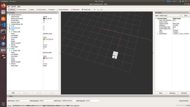
增益参数调整为 1.0 后勉强可以跟踪上参考轨迹

但横向跟踪误差和横摆角误差都很大,最大横向跟踪误差 0.4694m,最大横摆角误差 0.2868 rad,都是比较大的误差
感觉这里误差均值的意义不大,因为正误差与负误差会抵消,还需结合论文判断

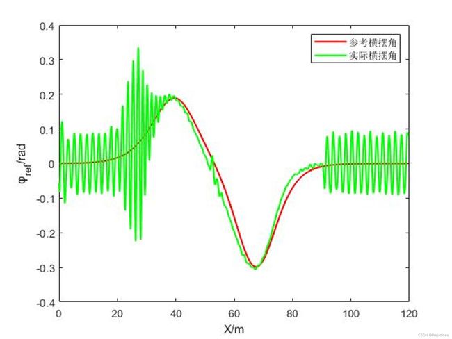

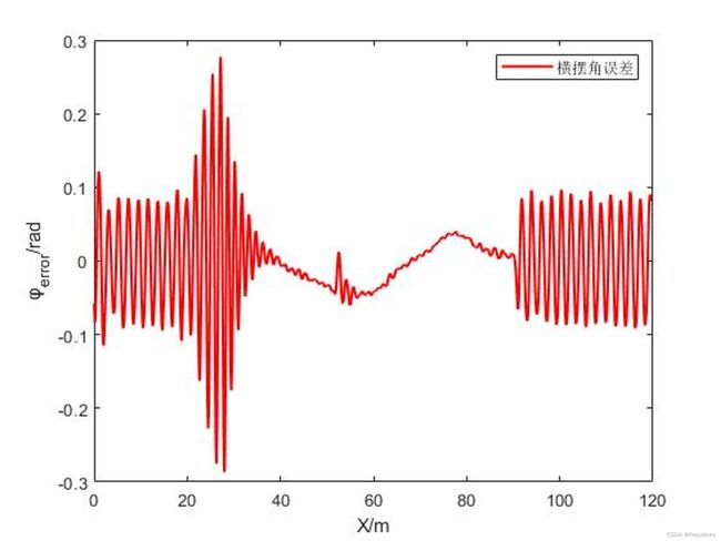
根据Stanley 轨迹跟踪算法研究(2)中 CarSim+Simulink 联合仿真结果可知:相同增益参数 Gain_K,速度越低越不稳定,前轮转角会存在越多的抖动;相同速度下,增益参数越大越不稳定,前轮转角会存在越多的抖动
考虑移动机器人纵向速度仅为 0.5m/s,速度较低,因此增益参数Gain_K应取小值,同时依然存在 Gazebo 关节控制器 PID 参数调教的问题