练习十二:利用SRAM设计一个FIFO
利用SRAM设计一个FIFO
-
-
- 1,任务目的
- 2,设计要求
- 3,FIFO接口的设计思路
- 4,FIFO接口的测试,top.v
- 5,FIFO接口的参考设计,fifo_interface.v
- 6,SRAM模型,sram.v代码
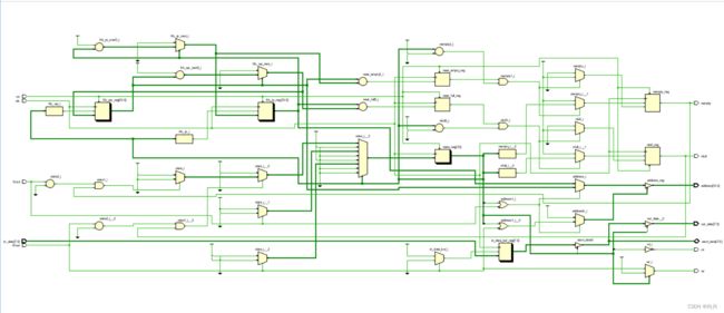
- 7,vivado生成的RTL原理图
- 8,波形图
-
- 8.1,波形全图
- 8.2,波形细化
- 9,
-
1,任务目的
(1)学习和掌握存取队列管理的状态机设计的基本方法;
(2)了解并掌握用存储器构成FIFO的接口设计的基本技术;
(3)用工程概念来编写完整的测试模块,达到完整测试覆盖;
在本练习中,要求利用练习十一中提供的SRAM模型,设计SRAM读写控制逻辑,使SRAM的行为对用户表现为一个FIFO(先进先出存储器)。
2,设计要求
本练习要求同学设计的FIFO 是
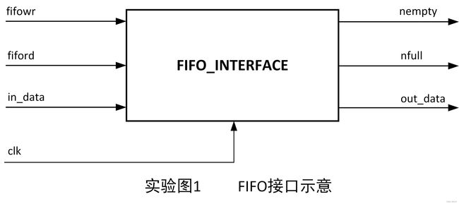
同步FIFO,即对FIFO的读/写使用同一个时钟。该FIFO应当提供用户读使能(fiford)和写使能(fifowr)输入控制信号,并输出指示FIFO状态的非空(nempty)和非满(nfull)信号,FIFO的输入、输出数据使用各自的数据总线:in_data和out_data。
3,FIFO接口的设计思路
4,FIFO接口的测试,top.v
在完成一个设计后,需要进行测试以确认设计的正确性和完整性。而要进行测试,就需要编写测试激励和结果检查程序,即测试平台(testbench)。在某些情况下,如果设计的接口能够预先确定,测试平台的编写也可以在设计完成之前就进行,
这样做的好处:在设计测试平台的同时也在更进一步深入了解设计要求,有助于理清设计思路,及时发现设计方案的错误。
编写测试激励时,除了注意对实际可能存在的各种情况的覆盖外,还要有意针对非正常情况下的操作进行测试。在本练习中,就应当进行在FIFO读空后继续读取,FIFO写满后继续写入和FIFO复位后马上读取等操作的测试。
测试激励中通常会有一些复杂操作需要反复进行,如本练习中对FIFO的读写操作。这时可以将这些复杂操作纳入到几个task中,即减少了激励编写的工作量,也使得程序的可读性更好。
下面的测试程序作为一个参考,先用这段程序测试所设计的FIFO接口,然后编写更全面的测试程序。
`timescale 1ns / 1ps
//
// Company:
// Engineer:
//
// Create Date: 2023/12/04 16:18:41
// Design Name:
// Module Name: test_fifo
// Project Name:
// Target Devices:
// Tool Versions:
// Description:
//
// Dependencies:
//
// Revision:
// Revision 0.01 - File Created
// Additional Comments:
//
//


//	测试信号

`define		FIFO_SIZE	8
//      `include	"sram.v"	//	所有的仿真工具不需要加这句,只要 sram.v 模块编译就可以了
`timescale	1ns/ 1ns

module	test_fifo;
reg		[7:0]	in_data;			//	FIFO 数据总线
reg				fiford, fifowr;		//	FIFO 控制信号

wire	[7:0]	out_data;
wire			nfull, nempty;		// 	FIFO 状态信号

reg				clk, rst;

wire	[7:0]	sram_data;			//	SRAM 数据总线
wire	[10:0]	address;			//  SRAM 地址总线
wire			rd, wr;				//  SRAM 读写控制信号

reg		[7:0]	data_buf	[`FIFO_SIZE:0];		// 数据缓存,用于结果检查
integer			index;

//	系统时钟
initial		clk = 0;
always		#25		clk = ~clk;

//	测试激励序列
initial		begin
		fiford		= 1;
		fifowr		= 1;
		rst			= 1;

#40		rst			= 0;
#42		rst			= 1;

if(nempty)		$display($time, "Error: FIFO be empty, nempty should be low. \n");

//		连续写 FIFO
		index		= 0;
repeat(`FIFO_SIZE)	begin
	data_buf[index]	= $random;
	write_fifo(data_buf[index]);
	index	= index + 1;
	end

if(nfull)	$display($time, "Error: FIFO full, nfull should be low. \n");
repeat(2)	write_fifo($random);

#200

//		连续读FIFO
		index		= 0;
read_fifo_compare(data_buf[index]);
if(~nfull)		$display($time, "Error: FIFO not full, nfull should be high. \n");

repeat(`FIFO_SIZE - 1)	begin
		index	 	= index + 1;
		read_fifo_compare(data_buf[index]);
end

if(nempty)	$display($time, "Error: FIFO be empty, nempty should be low. \n");

repeat(2)	read_fifo_compare(8'bx);

reset_fifo;

//		写后续 FIFO
repeat(`FIFO_SIZE * 2)		begin
	data_buf[0]		= $random;
	write_fifo(data_buf[0]);
	read_fifo_compare(data_buf[0]);
end

//		异常操作
reset_fifo;
read_fifo_compare(8'bx);
write_fifo(data_buf[0]);
read_fifo_compare(data_buf[0]);

$stop;

end

fifo_interface	fifo_mk(
.in_data			(in_data		),
.out_data			(out_data		),
.fiford				(fiford			),
.fifowr				(fifowr			),
.nfull				(nfull			),
.nempty				(nempty			),
.address			(address		),
.sram_data			(sram_data		),
.rd					(rd				),
.wr					(wr				),
.clk				(clk			),
.rst				(rst			)
);

sram	m1(
.Address			(address		),
.Data				(sram_data		),
.SRG				(rd				),		//	SRAM 读使能
.SRE				(1'b0			),		//	SRAM 片选,低有效
.SRW				(wr				)		//	SRAM 写使能
);

task			write_fifo;
input	[7:0]	data;

begin
		in_data		= data;
#50		fifowr		= 0;			//	往 SRAM 中写数
#200	fifowr		= 1;
#50;
end

endtask

task	read_fifo_compare;
input	[7:0]	data;
begin
#50		fiford		= 0;			// 从 SRAM 中读数
#200	fiford		= 1;
	if(out_data != data)
		$display($time, "Error: Data retrieved (%h) not match the one stored(%h) .\n", out_data, data);
#50;
end
endtask

task	reset_fifo;
begin
#40		rst			= 0;
#40		rst			= 1;
end
endtask

endmodule
5,FIFO接口的参考设计,fifo_interface.v
`timescale 1ns / 1ps
//
// Company:
// Engineer:
//
// Create Date: 2023/12/04 16:14:09
// Design Name:
// Module Name: fifo_interface
// Project Name:
// Target Devices:
// Tool Versions:
// Description:
//
// Dependencies:
//
// Revision:
// Revision 0.01 - File Created
// Additional Comments:
//
//


//	FIFO接口的参考设计
`define		SRAM_SIZE	8	// 为减少对 FIFO 控制器的测试工作量,置 SRAM 空间为 8 字节
//      `timescale	1ns/ 1ns

module	fifo_interface(
in_data,		// 	用户的输入数据总线
out_data, 		//	用户的输出数据总线
fiford,			//	FIFO读控制信号,低电平有效
fifowr,			//	FIFO写控制信号,低电平有效
nfull,			//
nempty,			//
address,		//	到 SRAM 的地址总线
sram_data,		//	到 SRAM 的双向数据总线
rd,				//	SRAM 读使能,低电平有效
wr,				//	SRAM 写使能,低电平有效
clk,			//	系统时钟信号
rst				//	全局复位信号,低电平有效
);
//	来自用户的控制输入信号
input			fiford, fifowr, clk, rst;

//	来自用户的数据信号
input	[7:0]	in_data;
output	[7:0]	out_data;

reg		[7:0]	in_data_buf;	//	输入数据缓冲区
reg		[7:0]	out_data_buf;	//	输出数据缓冲区

//	输出到用户的状态指示信号
output			nfull, nempty;
reg				nfull, nempty;

//	输出到 SRAM 的控制信号
output			rd, wr;

//	到 SRAM 的双向数据总线
inout	[7:0]	sram_data;

//	输出到 SRAM 的地址总线
output 	[10:0]	address;
reg		[10:0]	address;

//	internal register
reg		[10:0]	fifo_wp;		// 	FIFO写指针
reg		[10:0]	fifo_rp;		//	FIFO读指针

reg		[10:0]	fifo_wp_next;	//	fifo_wp 的下一个值
reg		[10:0]	fifo_rp_next;	//	fifo_rp	的下一个值

reg		near_full, near_empty;

reg		[3:0]	state;			//	SRAM 操作状态机寄存器

parameter		idle 			= 4'b0000;
parameter		read_ready		= 4'b0100;
parameter		read			= 4'b0101;
parameter		read_over		= 4'b0111;

parameter		write_ready		= 4'b1000;
parameter		write			= 4'b1001;
parameter		write_over		= 4'b1011;

//	SRAM 操作状态机
always@(posedge clk or negedge rst)
	if(~rst)
		state		<= idle;
	else
		case(state)
			idle:		// 等待 FIFO 的操作控制信号
				if(fifowr	== 0 && nfull)		//	用户发出写 FIFO 申请,且 FIFO 未满
					state	<= write_ready;
				else if(fiford == 0 && nempty)	//	用户发出读 FIFO 申请,且 FIFO 未空
					state	<= read_ready;
				else
					state	<= idle;			// 没有对 FIFO 操作的申请

			read_ready:		// 建立 SRAM 操作所需地址和数据
				state	<= read;

			read:			//	等待用户结束当前读操作
				if(fiford == 1)
					state	<= read_over;
				else
					state	<= read;

			read_over:		//	继续给出 SRAM 地址以保证数据稳定
				state	<= idle;

			write_ready:	//	建立 SRAM 操作所需地址和数据
				state	<= write;

			write:			//	等待用户结束当前写操作
				if(fifowr == 1)
					state	<= write_over;
				else
					state	<= write;
			write_over:		//	继续给出 SRAM 地址和写入数据以保证数据稳定
				state	<= idle;

			default:
				state	<= idle;
		endcase

//	产生 SRAM 操作相关信号
assign		rd = ~state[2];		// state 为 read_ready 或 read 或 read_over
assign		wr = (state == write) ? fifowr : 1'b1;

always@(posedge clk)
	if(~fifowr)
		in_data_buf		<= in_data;

assign		sram_data = (state[3])? in_data_buf : 8'hzz;
//	state 为 write_ready 或 write 或 write_over

always@(state or fiford or fifowr or fifo_wp or fifo_rp)
	if(state[2] || ~fiford)
		address		= fifo_rp;
	else if(state[3] || ~fifowr)
		address		= fifo_wp;
	else
		address		= 'bz;

//	产生 FIFO 数据
assign		out_data	= (state[2]) ? sram_data : 8'bz;

always@(posedge clk)
	if(state == read)
		out_data_buf	<= sram_data;

//	计算 FIFO 读写指针
always@(posedge clk or negedge rst)
	if(~rst)
		fifo_rp		<= 0;
	else if(state == read_over)
		fifo_rp		<= fifo_rp_next;

always@(fifo_rp)
	if(fifo_rp == `SRAM_SIZE - 1)
		fifo_rp_next	= 0;
	else
		fifo_rp_next	= fifo_rp + 1;

always@(posedge clk or negedge rst)
	if(~rst)
		fifo_wp		<= 0;
	else if(state == write_over)
		fifo_wp		<= fifo_wp_next;

always@(fifo_wp)
	if(fifo_wp == `SRAM_SIZE - 1)
		fifo_wp_next	= 0;
	else
		fifo_wp_next	= fifo_wp + 1;

always@(posedge clk or negedge rst)
	if(~rst)
		near_empty	<= 1'b0;
	else if(fifo_wp == fifo_rp_next)
		near_empty	<= 1'b1;
	else
		near_empty	<= 1'b0;

always@(posedge clk or negedge rst)
	if(~rst)
		nempty		<= 1'b0;
	else if(near_empty && state == read)
		nempty		<= 1'b0;
	else if(state == write)
		nempty		<= 1'b1;

always@(posedge clk or negedge rst)
	if(~rst)
		near_full	<= 1'b0;
	else if(fifo_rp == fifo_wp_next)
		near_full	<= 1'b1;
	else
		near_full	<= 1'b0;

always@(posedge clk or negedge rst)
	if(~rst)
		nfull		<= 1'b1;
	else if(near_full && state == write)
		nfull		<= 1'b0;
	else if(state == read)
		nfull		<= 1'b1;

//      //  调用 SRAM
//      sram	m1(
//      .Address			(address		),
//      .Data				(sram_data		),
//      .SRG				(rd				),		//	SRAM 读使能
//      .SRE				(1'b0			),		//	SRAM 片选,低有效
//      .SRW				(wr				)		//	SRAM 写使能
//      );

endmodule
6,SRAM模型,sram.v代码
`timescale 1ns / 1ps
//
// Company:
// Engineer:
//
// Create Date: 2023/12/04 16:18:04
// Design Name:
// Module Name: sram
// Project Name:
// Target Devices:
// Tool Versions:
// Description:
//
// Dependencies:
//
// Revision:
// Revision 0.01 - File Created
// Additional Comments:
//
//


`timescale 1ns / 1ps
//
// Company:
// Engineer:
//
// Create Date: 2023/12/01 17:38:38
// Design Name:
// Module Name: sram
// Project Name:
// Target Devices:
// Tool Versions:
// Description:
//
// Dependencies:
//
// Revision:
// Revision 0.01 - File Created
// Additional Comments:
//
//


/*	sram is Verilog HDL model for HM - 65162, 2K*8 bit Asynchronous(异步) CMOS
Static RAM. It is used in simulation to substitute the real RAM to verify whether
the writing or reading of the RAM is OK.
This module is a behavioral model for simulation only, not synthesizable. It's
writing and reading function are verified.
*/

module		sram(
Address, Data, SRG, SRE, SRW
);
input	[10:0]	Address;
input			SRG;	// output enable
input			SRE;	// chip   enable
input			SRW;	// write  enable

inout	[7:0]	Data;	// Bus

wire	[10:0]	Addr	= Address;
reg		[7:0]	RdData;
reg		[7:0]	SramMem	[0:'h7ff];
reg				RdSramDly,	RdFlip;
wire	[7:0]	FlpData;
wire	[7:0]	Data;

reg				WR_flag;	// to judge the signals according to the specification of
							// HM-65162
integer			i;

wire			RdSram = ~SRG & ~SRE;
wire			WrSram = ~SRW & ~SRE;

reg		[10:0]	DelayAddr;
reg		[7:0]	DelayData;
reg				WrSramDly;

integer			file;

assign			FlpData	= (RdFlip) 	  ? ~RdData : RdData;
assign			Data	= (RdSramDly) ? FlpData : 'hz;

/*
parameters of read circle
*/

//		参数序号、最大或最小、参数含义
parameter		TAVQV	= 90,	// 2, max, address access time
				TELQV	= 90,	// 3, max, chip enable access time
				TELQX	= 5,	// 4, min, chip enable output enable time
				TGLQV	= 65,	// 5, max, output enable access tiem
				TGLQX	= 5,	// 6, min, output enable output enable time
				TEHQZ 	= 50,	// 7, max, chip enable output disable time
				TGHQZ	= 40,	// 8, max, output enable output disable time
				TAVQX	= 5;	// 9, min, output hold from address change

parameter		TAVWL	= 10,	// 12, min, address setup time
				TWLWH	= 55,	// 13, min, chip enable pulse setup time,
											// write enable pluse width,
				TWHAX	= 15,	// 14, min10, write enable read setup time,
											// 读上升沿后地址保留时间
				TWLQZ	= 50,	// 16, max, write enable output disable time
				TDVWH	= 30,	// 17, min, data setup time
				TWHDX	= 20,	// 18, min15, data hold time
				TWHQX	= 20,	// 19, min0, write enable output enable time, 0
				TWLEH	= 55,	// 20, min, write enable pulse setup time
				TDVEH	= 30,	// 21, min, chip enable data setup time
				TAVWH	= 70;	// 22, min65, address valid to end of write

initial		begin
	file = $fopen("ramlow.txt");
	if(!file)	begin
		$display("Could not open the file.");
		$stop;
		end
end

initial		begin
	for(i = 0; i < 'h7ff; i = i + 1)
		SramMem[i] = i;
	// monitor($time, "DelayAddr = %h, DelayData = %h", DelayAddr, DelayData);
end

initial		RdSramDly	= 0;
initial		WR_flag		= 1;

//		READ CIRCLE
always@(posedge RdSram)		#TGLQX	RdSramDly = RdSram;
always@(posedge SRW)		#TWHQX	RdSramDly = RdSram;
always@(Addr)	begin
	#TAVQX;
	RdFlip	= 1;
	#(TGLQV - TAVQX);		// address access time
	if(RdSram)
		RdFlip = 0;
end

always@(posedge RdSram)	begin
	RdFlip	= 1;
	#TAVQV;					// output enable access time
	if(RdSram)
		RdFlip = 0;
end

always@(Addr)			#TAVQX	RdFlip 		= 1;
always@(posedge SRG)	#TEHQZ	RdSramDly	= RdSram;
always@(posedge SRE)	#TGHQZ	RdSramDly	= RdSram;
always@(negedge SRW)	#TWLQZ	RdSramDly	= 0;

always@(negedge WrSramDly or posedge RdSramDly)		RdData = SramMem[Addr];

//		WRITE CIRCLE
always@(Addr)			#TAVWL	DelayAddr	= Addr;		// Address setup
always@(Data)			#TDVWH	DelayData	= Data;		// Data setup
always@(WrSram)			#5		WrSramDly	= WrSram;
always@(Addr or Data or WrSram)	WR_flag		= 1;

always@(negedge SRW)	begin
	#TWLWH;					// Write enable pulse width
	if(SRW)		begin
		WR_flag		= 0;
		$display("ERROR! Can't write! Write enable time(W) is too short!");
		end
end

always@(negedge SRW)	begin
	#TWLEH;					// Write enable pulse setup time
	if(SRE)		begin
		WR_flag		= 0;
		$display("ERROR! Can't write! write enable pulse setup time(E) is too short!");
		end
end

always@(posedge SRW)	begin
	#TWHAX;					// Write enable read setup time
	if(DelayAddr !== Addr)	begin
		WR_flag		= 0;
		$display("ERROR! Can't write! Write enable read setup time is too short!");
		end
end

always@(Data)
	if(WrSram)	begin
		#TDVEH;				// chip enable data setup time
		if(SRE)		begin
			WR_flag	= 0;
			$display("ERROR! Can't write! chip enable data setup time is too short!");
			end
end

always@(Data)
	if(WrSram)	begin
		#TDVEH;
		if(SRW)		begin
			WR_flag = 0;
			$display("ERROR! Can't write! chip enable data setup time is too short!");
			end
end

always@(posedge SRW)	begin
	#TWHDX;			// Data hold time
	if(DelayData !== Data)
		$display("Warning! Data hold time is too short!");
end

always@(DelayAddr or DelayData or WrSramDly)
	if(WrSram && WR_flag)	begin
		if(!Addr[5])	begin
				#15	SramMem[Addr]	= Data;
					//	$display("mem[%h] = %h", Addr, Data);
					$fwrite(file, "mem[%h] = %h", Addr, Data);
					if(Addr[0] && Addr[1])	$fwrite(file, "\n");
			end
		else	begin
			$fclose(file);
			$display("Please check the txt.");
			$stop;
			end
end

endmodule


