B站台湾大学郭彦甫|MATLAB 学习笔记|06 高阶绘图 Advanced Plot
MATLAB学习笔记(06 高阶绘图 Advanced Plot)
如果想获得更好浏览体验的朋友可以转到下面链接 06
1. 对数图 (Logarithm Plots)
x = logspace(-1,1,100); %logspace()生成对数间距向量,此处表达的含义是X矩阵是在10^(-1)和10^(1)之间生成100个点。
y = x.^2;

subplot(2,2,1);
plot(x,y);        %正常坐标轴的图形
title('Plot');

subplot(2,2,2);
semilogx(x,y);		%X轴为对数坐标轴,Y轴为正常坐标轴的图形
title('Semilogx');

subplot(2,2,3);
semilogy(x,y);    %Y轴为对数坐标轴,X轴为正常坐标轴的图形
title('Semilogy');

subplot(2,2,4);
loglog(x, y);     %X轴为对数坐标轴,Y轴为对数坐标轴的图形
title('Loglog');

set(gca,'XGrid','on');		%给X轴加网格

2. 直方图 (Histogram)
y = randn(1,1000);

subplot(2,1,1);
hist(y,10);   %基于y创建直方图,且直方图的bin数量为10
title('Bins = 10');

subplot(2,1,2);
hist(y,50);    %直方图的bin数量为50
title('Bins = 50');

3. 条形图 (Bar Chart)
x = [1 2 5 4 8];  y = [x;1:5];

subplot(1,3,1);  bar(x);  title('A bargraph of vector x');
%bar(x)创建一个条形图,x中的每个元素对应一个条形。

subplot(1,3,2);  bar(y);  title('A bargraph of vector y');
%关于数组y的条形图, 如果 y 是 m×n (2*5)矩阵,则 bar 创建每组包含 n (5)个条形的 m (2)个组。


subplot(1,3,3);  bar3(y);  title('A 3D bargraph');
%关于数组y的三维条形图,y 中的每个元素对应一个条形图,  y 轴的刻度范围是从 1 到 y 的行数(2)。

- 堆叠型和水平型条状图 (Stacked and Horizontal Bar Charts)
x = [1 2 5 4 8];
y = [x;1:5];

subplot(1,2,1); bar(y,'stacked'); title('Stacked');
%堆叠型条状图

subplot(1,2,2); barh(y); title('Horizontal');
%水平型条状图

P9 exercise:
题目:stack the horizontal bar chart
x = [1 2 5 4 8];
y = [x;1:5];

barh(y,'stacked'); title('Horizontal Stacked barplot');
%水平型堆叠条状图

4. 饼状图 (Pie Charts)
a = [10 5 20 30];

subplot(1,3,1);  pie(a);
%对a中的值进行归一化然后画图

subplot(1,3,2);  pie(a,[0,0,0,1]);
%pie(X,explode) 将扇区从饼图偏移一定位置。
%explode 是一个由与 X 对应的零值和非零值组成的向量或矩阵。
%pie 函数仅将对应于 explode 中的非零元素的扇区偏移一定的位置。


subplot(1,3,3);  pie3(a, [0,0,0,1]);
%使用 a 中的数据绘制三维饼图。

P9 exercise
题目:separate all the pieces in the pie chart
a = [10 5 20 30];


subplot(1,3,2);  pie(a,[2,1,3,100]);
%矩阵内的数字是随便打的,矩阵中的非零数字对应地将饼状图部分分开

subplot(1,3,3);  pie3(a, [21,3,4,1]);

5. 极坐标图 (Polar Chart)
x = 1:100;

theta = x/10;
r = log10(x);
subplot(1,4,1);  polar(theta,r);

theta = linspace(0, 2*pi);  %返回(2,2pi)的一百个等间距点(包含 2 和 2pi)
r = cos(4*theta);
subplot(1,4,2);  polar(theta,r);

theta = linspace(0, 2*pi, 6); %返回六个点
r = ones(1,length(theta));  %返回全为1的矩阵(1*6)
subplot(1,4,3);  polar(theta,r);

theta = linspace(0, 2*pi); r = 1-sin(theta);
subplot(1,4,4);  polar(theta,r);

P10 exercise
题目:plot a hexagon(六边形) on a polar chart
用上面的第三个图(五边形)代码修改
x = 1:100;

theta = linspace(0, 2*pi, 7); %返回7个点
r = ones(1,length(theta));  %返回全为1的矩阵(1*7)
polar(theta,r);
6. 绘制阶梯图和离散序列数据 (Stair and Stem(柱子) Charts)
x = linspace(0, 4*pi, 40);
y = sin(x);

subplot(1,2,1);
stairs(y); %绘制阶梯图

subplot(1,2,2);
stem(y);		%绘制离散数据序列

P12 exercise
题目:
Plot a function: f ( t ) = sin ( π t 2 4 ) f(t)=\sin \left(\frac{\pi t^{2}}{4}\right) f(t)=sin(4πt2)
Add the points sampled at 5 H z 5 \mathrm{~Hz} 5 Hz using s t e m ( ) stem () stem()

需要画出两条曲线,一个是连续函数f(t)(看起来连续),另一个是采样频率为5Hz的离散序列
t= linspace(0,10,100);
f=sin((pi*t.^2)/4);

%频率f=5Hz,T= 1/f= 0.2s,即每0.2s取一个采样点
T=[0:0.2:10];
F=sin((pi*T.^2)/4);

hold on
stem(T,F);  %离散序列
plot(t,f);	%连续函数
hold off

set(gca,’FontSize‘,20);
xlabel(’time(s)‘); %加个标签说明我不是把PPT中的图剪切上来的

7. 箱线图和含误差条的线图 (Boxplot and Error Bar)
- 箱线图
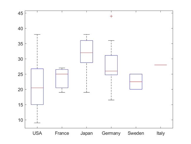
箱线图(Box-plot)是一种用于显示一组数据分散情况的统计图,多用于多组数据的比较。
在每个箱子上,中心标记表示中位数,箱子的底边和顶边分别表示第 25 个和 75 个百分位数。虚线会延伸到不是离群值(可以理解为距离数据平均值非常远的数值,统计时应当舍去)的最远端数据点,离群值会使用 ‘+’ 标记符号单独绘制。
load carsmall %加载样本数据

boxplot(MPG, Origin);  %创建一个表示每加仑英里数 (MPG) 测量值的箱线图,按测量的原产国 (Origin) 分组

%boxplot(x,g) 使用 g 中包含的一个或多个分组变量创建箱线图

- 含误差条的线图 (error bar)
x=0:pi/10:pi; y=sin(x);

e=std(y)*ones(size(x));
% size(x)返回一个行向量([1 11]),ones(size(x))得到该维度(1行11列)的全为1的行向量
%std(y)返回y的标准差,e表示关于y的标准差矩阵,其大小由x的尺寸所决定。

errorbar(x,y,e) %
%errorbar(x,y,e) 绘制 y 对 x 的图,并在每个数据点处绘制一个垂直误差条,
%e 表示每个数据点上方和下方误差条的长度

8. fill() (填充二维多边形)
t =(1:2:15)'*pi/8;  x = sin(t);  y = cos(t);

fill(x,y,'r');    %依据 x 和 y 中的数据创建填充的图形,填充封闭图形为红色
axis square off;  %关闭直角坐标系

text(0,0,'STOP','Color', 'w', 'FontSize', 80, ...
	'FontWeight','bold', 'HorizontalAlignment', 'center');
%FontWeight 表示字体粗细,HorizontalAlignment 表示文本框中的文本水平对齐

P15 exercise
题目:Plot a wait sign

x=[2 0 -2 0];
y=[0 -2 0 2];

fill(x,y,'y','linewidth',10);
axis square off;
title('my pic','FontSize',20); %加个title表示是自己画的

text(0,0, 'WAIT','Color','k','FontSize',80,...
    'FontWeight','bold','HorizontalAlignment','center');

9. Color Space
P17 exercise
题目:
G = [46 38 29 24 13]; S = [29 27 17 26 8];
B = [29 23 19 32 7]; h = bar(1:5, [G' S' B']);
title('Medal count for top 5 countries in 2012 Olympics');
ylabel('Number of medals'); xlabel('Country');
legend('Gold', 'Silver', 'Bronze')

修改后的代码如下:
G = [46 38 29 24 13];
S = [29 27 17 26 8];
B = [29 23 19 32 7];

h = bar(1:5, [G' S' B'],'FaceColor','flat'); %'表示转置
%bar(x,y) 在 x指定的位置绘制条形,y是5*3的矩阵,得到的h是5组每组3条的bar图

xticklabels({'USA','CHN','GBR','RUS','KOR'});
%经查找,xticklabels可以直接对多个xticklabel进行设置。

set(gca,'FontSize',20);
title('Medal count for top 5 countries in 2012 Olympics');
ylabel('Number of medals');  xlabel('Country');
legend('Gold', 'Silver', 'Bronze')

%以上得到未更改条形颜色的条形图

set(h(1),'FaceColor','#CCCC00');
%查百度知道的,h是一个1*3的bar阵列,每个bar里面有五组数据,此处设置第一个bar的颜色为gold,以此类推

set(h(2),'FaceColor','#CCCCCC');

set(h(3),'FaceColor','#996666');

10. imagesc() (可视化数据的图像)
[x, y] = meshgrid(-3:.2:3,-3:.2:3);
%对于 [X, Y]=(x, y), X和Y 是 y*x 规格的矩阵,
%其中X的每一行是x的副本,Y中的每一列是y的副本

z = x.^2 + x.*y + y.^2;

surf( x, y, z);  %创建一个三维曲面图
box on;

set(gca,'FontSize', 16);

zlabel('z');
xlim([-4 4]);  xlabel('x');
ylim([-4 4]);  ylabel('y');

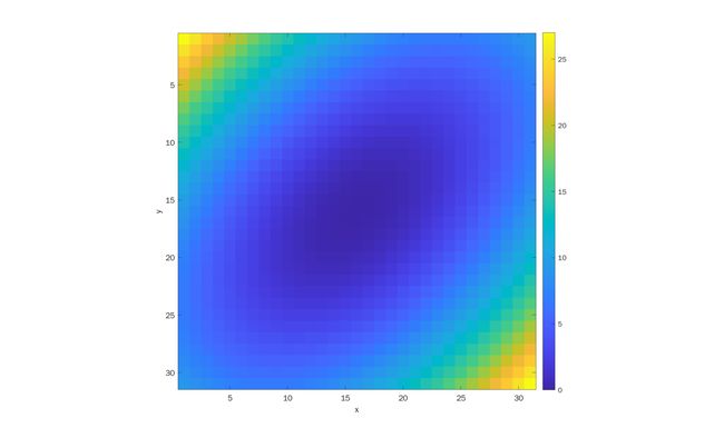
[x, y] = meshgrid(-3:.2:3,-3:.2:3);

z = x.^2 + x.*y + y.^2;

imagesc(z); %显示矩阵数据的图像,其中 z 中的最小值映射到颜色图中的第一种颜色,最大值映射到最后一种颜色。
axis square; xlabel('x'); ylabel('y')
colorbar; %显示颜色栏

11. 内建颜色图
- 使用MATLAB内建颜色图
colormap([Name]) %Name 的选取如下图

%colormap 矩阵的规格为 256*3
a= colormap([Name])

%自定义colormap,举例:
a= ones(256, 3);
colormap(a);
P22 exercise:
题目:Create a custom green color map such that the output of the script below looks like:
x = [1:10; 3:12; 5:14]; imagesc(x); colorbar; %此处是把矩阵x中的数据可视化为图像,并没有得到一个自定义colormap

%以下为自定义colormap程序
map = zeros(256,3);
map(:,2) = (0:255)/255;
colormap(map);
%map 是颜色图,map矩阵中的每一行均使用 RGB 三元组定义一种颜色,map矩阵中只有第二列有数值,所以得到的 colormap 全为绿色

12. 3D Plot
- 一些重要函数
| Function | Description |
|---|---|
| plot3 | 3-D line plot |
| surf | 3-D shaded surface plot |
| surfc | Contour plot under a 3-D shaded surface plot |
| surface | Create surface object |
| meshc | Plot a contour graph under mesh graph |
| contour | Contour plot of matrix |
| contourf | Filled 2-D contour plot |
- plot3()
x=0:0.1:3*pi;  z1=sin(x);  z2=sin(2.*x);  z3=sin(3.*x);

y1=zeros(size(x));   %得到的是一个行向量
y3=ones(size(x));   %得到的也是一个行向量
y2=y3./2;

plot3(x,y1,z1,'r',x,y2,z2,'b',x,y3,z3,'g'); grid on;

xlabel('x-axis');  ylabel('y-axis');  zlabel('z-axis');

13. Surface Plot
x = -3.5:0.2:3.5;   %设置x的范围
y = -3.5:0.2:3.5;   %设置y的范围

[X,Y] = meshgrid(x,y);   %生成一个与坐标x,y相关的网格
Z = X.*exp(-X.^2-Y.^2);   %计算每个平面坐标点对应的z值
%可以在命令后中输入X,Y,观察其值


subplot(1,2,1); mesh(X,Y,Z);  title('mesh plot');
subplot(1,2,2); surf(X,Y,Z);  title('surf plot');  %surf上的网格有贴图

- contour()
将等高的3D绘图投影到2D平面上
x = -3.5:0.2:3.5;
y = -3.5:0.2:3.5;
[X,Y] = meshgrid(x,y);
Z = X.*exp(-X.^2-Y.^2);
subplot(2,1,1);
mesh(X,Y,Z);
axis square;
subplot(2,1,2);
contour(X,Y,Z);  %投影
axis square;

- 多种投影绘图
x = -3.5:0.2:3.5; y = -3.5:0.2:3.5;
[X,Y] = meshgrid(x,y); Z = X.*exp(-X.^2-Y.^2);

subplot(1,3,1); contour(Z,[-.45:.05:.45]);   %调整等高线的疏密程度
%contour(Z),相比contour(X, Y, Z)没有准确的X,Y坐标
axis square;

subplot(1,3,2); [C,h] = contour(Z);  %[C,h] = contour() 返回等高线矩阵 C 和等高线对象 h
clabel(C,h);   %clabel(C,h) 为当前等高线图添加标签
axis square;

subplot(1,3,3); contourf(Z);   %然后显示 Z 的填充等高线图
axis square;

P30 exercise:
题目:Combine the contour techniques to generate a figure as shown below

其中等高线是一格 0.05 ,等高线上需要标数值,且为等高线填充颜色
x = -3.5:0.2:3.5; y = -3.5:0.2:3.5;
[X,Y] = meshgrid(x,y); Z = X.*exp(-X.^2-Y.^2);

[C,h] = contourf(X,Y,Z,[-0.4:0.05:0.4]);  %contour()括号中要加X,Y才能得到正确的坐标轴
clabel(C,h);
axis square;

%至此得到基本的等高线图,下面对坐标轴进行变换

xlim([-2,2]);
ylim([-2,2]);

colormap('default');  %设置为默认色图

- meshc() & surfc()
x = -3.5:0.2:3.5; y = -3.5:0.2:3.5;
[X,Y] = meshgrid(x,y); Z = X.*exp(-X.^2-Y.^2);

subplot(1,2,1); meshc(X,Y,Z);  %有投影的mesh()
subplot(1,2,2); surfc(X,Y,Z);  %有投影的surf()

14. 视角 (View Angle)
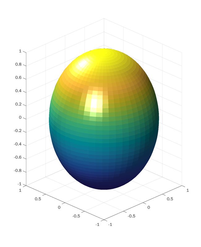
view(az,el) 为当前坐标区设置相机视线的方位角和仰角。

sphere(50);  %得到半径为1,50*50个面的球面
shading flat; %shading()设置颜色着色属性
%shading flat 表示每个网格线段和面具有恒定颜色,该颜色由该线段的端点或该面的角边处具有最小索引的颜色值确定。

L1= light('Position',[1 3 2]);  %打光位置,用set(L1,'Position',[]) 可以改变打光位置
L2= light('Position',[-3 -1 3]);
material shiny;  %控制曲面和补片的反射属性。
%material shiny 使得对象具有相对于漫反射和环境光更高的镜面反射,镜面反射光的颜色仅取决于光源的颜色。

set(gcf,'Color',[1 1 1]);
view(-45,20);

15. 绘制3D多边形
v = [0 0 0; 1 0 0 ; 1 1 0; 0 1 0; 0.25 0.25 1; ...
0.75 0.25 1; 0.75 0.75 1; 0.25 0.75 1];
f = [1 2 3 4; 5 6 7 8; 1 2 6 5; 2 3 7 6; 3 4 8 7; 4 1 5 8];

subplot(1,2,1);  patch('Vertices', v, 'Faces',f,...%vertices (v)指顶点位置,faces (f)定义要连接的顶点
'FaceVertexCData', hsv(6), ...%FaceVertexCData 制定一个数组表示每个面对应一种颜色
'FaceColor', 'flat');  %颜色可以是同一颜色,使用flat 且为每个顶点指定不同颜色,则指定的第一个顶点的颜色决定面的颜色


view(3);  %3 表示三维视角
axis square tight;  grid on;

subplot(1,2,2);  patch('Vertices', v, 'Faces', f, ...
'FaceVertexCData', hsv(8),...
'FaceColor', 'interp');  %颜色基于每个面的顶点颜色通过插值来计算,对于插补颜色,请将此属性指定为 'interp'。

view(3);  axis square tight;  grid on;


