【GD32F427开发板试用】CAN总线了解和回环测试
本篇文章来自极术社区与兆易创新组织的GD32F427开发板评测活动,更多开发板试用活动请关注极术社区网站。作者:HonestQiao
CAN总线是个好东西,据说用了的都说好。只要是09年之后的车都有CAN总线,要是摸得透的话,你还能通过CAN总线获取汽车的信息,甚至小小的控制一把。
以下为一位大佬做的测试:
一、开发板CAN总线了解
通过GD32F427的用户手册,欣喜的发现,也支持CAN总线:
于是就想学习研究一番,看看能不能跟家里的买菜车挂上钩。
一番了解,GD32F427开发板上的CAN总线,就是个CAN总线,还需要CAN收发器,才能真正用起来。
在其他的板子上找了找,原来是这样的:
上图中,两颗A1042/3的芯片,就是CAN收发器专用芯片。
去某宝上找了一下,选了下面的收发器模块:
二、CAN回环通讯演示代码
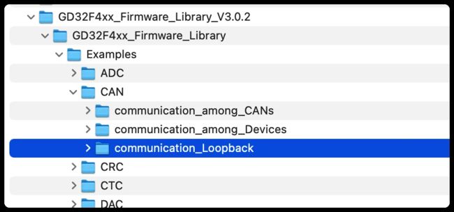
兵马未动粮草先行,官方演示代码中,提供了回环测试的代码,可以先进行测试了解:
该实例,是基于 GD32450I-EVAL-V1.1 开发板的,其中的基本逻辑如下:
-
标准CAN数据帧收发测试:
- 先通过以500Kbps轮询来执行标准数据帧的发送和接收。
- 如果接收帧成功,则LED1亮。否则,LED1熄灭。
-
CAN扩展帧数据收发测试,中断处理接收:
- 以500Kbps传输扩展数据帧。
- 当消息在FIFO1中挂起时,在中断处理程序中完成接收。
- 如果接收帧成功,则LED2亮起。否则,LED2熄灭。
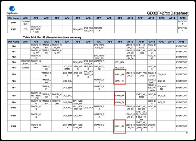
GD32450I有两个CAN接口,GD32F427也有两个CAN接口,通过数据手册可以详细了解:
每个CAN接口,都有两组GPIO口可供使用。
这些GPIO口都是可以复用的,如果在代码中进行配置,就会启用,否则默认不会启用。
三、自定义代码
GD32450I-EVAL有三个LED可供用户使用,然而,GD32F427开发板只有一个LED可供用户使用,从原理图上可以了解:
板载的LED对应的引脚为PC6,具体实物如下:
从演示代码中的LED定义,也可以看到:
既然如此,那就自己接了一个三色交通灯模块,使用PD13、PD14、PD15来进行控制,具体如下:
实物如下:
然后,参考演示代码中控制LED的方式,写了自己的LED控制调用:
#define LED_1_PIN                         GPIO_PIN_13
#define LED_1_GPIO_PORT                   GPIOD
#define LED_1_GPIO_CLK                    RCU_GPIOD

#define LED_2_PIN                         GPIO_PIN_14
#define LED_2_GPIO_PORT                   GPIOD
#define LED_2_GPIO_CLK                    RCU_GPIOD

#define LED_3_PIN                         GPIO_PIN_15
#define LED_3_GPIO_PORT                   GPIOD
#define LED_3_GPIO_CLK                    RCU_GPIOD

static uint32_t GPIO_PORT_USER[LED_n]           = {LED_1_GPIO_PORT, LED_2_GPIO_PORT, LED_3_GPIO_PORT};
static uint32_t GPIO_PIN_USER[LED_n]            = {LED_1_PIN, LED_2_PIN, LED_3_PIN};
static rcu_periph_enum GPIO_CLK_USER[LED_n]     = {LED_1_GPIO_CLK, LED_2_GPIO_CLK, LED_3_GPIO_CLK};

/* function declarations */
/* configure led GPIO */
void gd_eval_led_init_user(led_typedef_enum_user led_num);
/* turn on selected led */
void gd_eval_led_on_user(led_typedef_enum_user led_num);
/* turn off selected led */
void gd_eval_led_off_user(led_typedef_enum_user led_num);
/* toggle the selected led */
void gd_eval_led_toggle_user(led_typedef_enum_user led_num);

/*!
    \brief      configure the leds
    \param[in]  none
    \param[out] none
    \retval     none
*/
void led_config(void)
{
    gd_eval_led_init_user(LED_1);
    gd_eval_led_init_user(LED_2);
    gd_eval_led_init_user(LED_3);
}


/*!
    \brief      configure led GPIO
    \param[in]  led_num: specify the led to be configured
      \arg        LED2
    \param[out] none
    \retval     none
*/
void  gd_eval_led_init_user(led_typedef_enum_user led_num)
{
    /* enable the led clock */
    rcu_periph_clock_enable(GPIO_CLK_USER[led_num]);

    /* configure led GPIO port */
    gpio_mode_set(GPIO_PORT_USER[led_num], GPIO_MODE_OUTPUT, GPIO_PUPD_NONE,GPIO_PIN_USER[led_num]);
    gpio_output_options_set(GPIO_PORT_USER[led_num], GPIO_OTYPE_PP, GPIO_OSPEED_50MHZ,GPIO_PIN_USER[led_num]);

    GPIO_BC(GPIO_PORT_USER[led_num]) = GPIO_PIN_USER[led_num];
}

/*!
    \brief      turn on selected led
    \param[in]  led_num: specify the led to be turned on
      \arg        LED2
    \param[out] none
    \retval     none
*/
void gd_eval_led_on_user(led_typedef_enum_user led_num)
{
    GPIO_BOP(GPIO_PORT_USER[led_num]) = GPIO_PIN_USER[led_num];
}

/*!
    \brief      turn off selected led
    \param[in]  led_num: specify the led to be turned off
      \arg        LED2
    \param[out] none
    \retval     none
*/
void gd_eval_led_off_user(led_typedef_enum_user led_num)
{
    GPIO_BC(GPIO_PORT_USER[led_num]) = GPIO_PIN_USER[led_num];
}

/*!
    \brief      toggle selected led
    \param[in]  led_num: specify the led to be toggled
      \arg        LED2
    \param[out] none
    \retval     none
*/
void gd_eval_led_toggle_user(led_typedef_enum_user led_num)
{
    GPIO_TG(GPIO_PORT_USER[led_num]) = GPIO_PIN_USER[led_num];
}
代码说明:
- 初始化LED引脚配置:gd_eval_led_init_user(led_typedef_enum_user led_num);
- 点亮指定的LED:gd_eval_led_on_user(led_typedef_enum_user led_num);
- 熄灭指定的LED:gd_eval_led_off_user(led_typedef_enum_user led_num);
- 切换指定的LED状态:gd_eval_led_toggle_user(led_typedef_enum_user led_num);
前面说了,CAN总线有两个接口,分别为CAN0、CAN1,实测测试中,我选用了CAN1,对应的GPIO接口使用PB5、PB6:
对应在扩展接口的位置:
这两个接口,如果不在代码中做相应的定义,那么就不会有任何输出。
启用对应接口的定义如下:
#define CANx_RCU  RCU_GPIOB
#define CANx_GROUP  GPIOB
#define CANx_RX_PIN GPIO_PIN_5
#define CANx_TX_PIN GPIO_PIN_6

/*!
    \brief      initialize CAN and filter
    \param[in]  can_parameter
      \arg        can_parameter_struct
    \param[in]  can_filter
      \arg        can_filter_parameter_struct
    \param[out] none
    \retval     none
*/
void can_loopback_init(void)
{
    can_parameter_struct        can_parameter;
    can_filter_parameter_struct can_filter;

    rcu_periph_clock_enable(RCU_CAN1);
    rcu_periph_clock_enable(CANx_RCU);

    gpio_output_options_set(CANx_GROUP, GPIO_OTYPE_PP, GPIO_OSPEED_50MHZ, CANx_RX_PIN);//configure CAN1 GPIO, CAN1_RX(PB5)
    gpio_mode_set(CANx_GROUP, GPIO_MODE_AF, GPIO_PUPD_NONE, CANx_RX_PIN);
    gpio_af_set(CANx_GROUP, GPIO_AF_9, CANx_RX_PIN);

    gpio_output_options_set(CANx_GROUP, GPIO_OTYPE_PP, GPIO_OSPEED_50MHZ, CANx_TX_PIN);//configure CAN1 GPIO, CAN1_TX(PB6)
    gpio_mode_set(CANx_GROUP, GPIO_MODE_AF, GPIO_PUPD_NONE, CANx_TX_PIN);
    gpio_af_set(CANx_GROUP, GPIO_AF_9, CANx_TX_PIN);

    // ...
}
上述代码中,关键调用如下:
- rcu_periph_clock_enable:使能对应的外设时钟
- gpio_output_options_set:设置GPIO输出模式和速度
- gpio_mode_set:设置GPIO模式
- gpio_af_set:设置GPIO复用功能,PB5、PB6启用CAN1通讯功能,使用GPIO_AF_9
关于上述调用的具体使用方法,可以在固件库使用指南中查看详情。
在对CAN总线进行初始化设置中,有个参数需要注意:
/* initialize CAN */
    can_parameter.time_triggered = DISABLE;
    can_parameter.auto_bus_off_recovery = DISABLE;
    can_parameter.auto_wake_up = DISABLE;
    can_parameter.auto_retrans = ENABLE;
    can_parameter.rec_fifo_overwrite = DISABLE;
    can_parameter.trans_fifo_order = DISABLE;
    can_parameter.working_mode = CAN_LOOPBACK_MODE;
    /* configure baudrate to 500kbps */
    can_parameter.resync_jump_width = CAN_BT_SJW_1TQ;
    can_parameter.time_segment_1 = CAN_BT_BS1_7TQ;
    can_parameter.time_segment_2 = CAN_BT_BS2_2TQ;
    can_parameter.prescaler = 10;
    can_init(CANX, &can_parameter);
上述代码中,设置了can_parameter.working_mode为CAN_LOOPBACK_MODE。
CAN总线的通讯模式,分为4种:
- CAN_NORMAL_MODE:正常通讯模式
- CAN_LOOPBACK_MODE:回环通讯模式,发出去的数据,可以自己收到,也会发送到CAN总线网络上
- CAN_SILENT_MODE:静默通讯模式,就是侦听,不发送数据
- CAN_SILENT_LOOPBACK_MODE:回环静默通讯模式,就是自己回环玩自己的,不与CAN总线网络发生联系
在回环测试中,选用CAN_LOOPBACK_MODE模式。
因为同时配置了CAN1对应的PB5、PB6,所以,可以在PB5、PB6挂上一个逻辑分析仪,查看是否有波形输出。
最终,实际修改后的代码如下:
/*!
    \file    main.c
    \brief   communication_Loopback in normal mode

    \version 2016-08-15, V1.0.0, firmware for GD32F4xx
    \version 2018-12-12, V2.0.0, firmware for GD32F4xx
    \version 2020-09-30, V2.1.0, firmware for GD32F4xx
    \version 2022-03-09, V3.0.0, firmware for GD32F4xx
*/

/*
    Copyright (c) 2022, GigaDevice Semiconductor Inc.

    Redistribution and use in source and binary forms, with or without modification,
are permitted provided that the following conditions are met:

    1. Redistributions of source code must retain the above copyright notice, this
       list of conditions and the following disclaimer.
    2. Redistributions in binary form must reproduce the above copyright notice,
       this list of conditions and the following disclaimer in the documentation
       and/or other materials provided with the distribution.
    3. Neither the name of the copyright holder nor the names of its contributors
       may be used to endorse or promote products derived from this software without
       specific prior written permission.

    THIS SOFTWARE IS PROVIDED BY THE COPYRIGHT HOLDERS AND CONTRIBUTORS "AS IS"
AND ANY EXPRESS OR IMPLIED WARRANTIES, INCLUDING, BUT NOT LIMITED TO, THE IMPLIED
WARRANTIES OF MERCHANTABILITY AND FITNESS FOR A PARTICULAR PURPOSE ARE DISCLAIMED.
IN NO EVENT SHALL THE COPYRIGHT HOLDER OR CONTRIBUTORS BE LIABLE FOR ANY DIRECT,
INDIRECT, INCIDENTAL, SPECIAL, EXEMPLARY, OR CONSEQUENTIAL DAMAGES (INCLUDING, BUT
NOT LIMITED TO, PROCUREMENT OF SUBSTITUTE GOODS OR SERVICES; LOSS OF USE, DATA, OR
PROFITS; OR BUSINESS INTERRUPTION) HOWEVER CAUSED AND ON ANY THEORY OF LIABILITY,
WHETHER IN CONTRACT, STRICT LIABILITY, OR TORT (INCLUDING NEGLIGENCE OR OTHERWISE)
ARISING IN ANY WAY OUT OF THE USE OF THIS SOFTWARE, EVEN IF ADVISED OF THE POSSIBILITY
OF SUCH DAMAGE.
*/

#include "gd32f4xx.h"
#include
#include "gd32f427v_start.h"
#include "systick.h"

/* select CAN */
//#define CAN0_USED
#define CAN1_USED

#ifdef  CAN0_USED
    #define CANX CAN0
#else
    #define CANX CAN1
#endif

#define CANx_RCU  RCU_GPIOB
#define CANx_GROUP  GPIOB
#define CANx_RX_PIN GPIO_PIN_5
#define CANx_TX_PIN GPIO_PIN_6

/* eval board low layer led */
#define LED_n                             3U

/* exported types */
typedef enum
{
    LED_1,
    LED_2,
    LED_3
} led_typedef_enum_user;

#define LED_1_PIN                         GPIO_PIN_13
#define LED_1_GPIO_PORT                   GPIOD
#define LED_1_GPIO_CLK                    RCU_GPIOD

#define LED_2_PIN                         GPIO_PIN_14
#define LED_2_GPIO_PORT                   GPIOD
#define LED_2_GPIO_CLK                    RCU_GPIOD

#define LED_3_PIN                         GPIO_PIN_15
#define LED_3_GPIO_PORT                   GPIOD
#define LED_3_GPIO_CLK                    RCU_GPIOD

static uint32_t GPIO_PORT_USER[LED_n]           = {LED_1_GPIO_PORT, LED_2_GPIO_PORT, LED_3_GPIO_PORT};
static uint32_t GPIO_PIN_USER[LED_n]            = {LED_1_PIN, LED_2_PIN, LED_3_PIN};
static rcu_periph_enum GPIO_CLK_USER[LED_n]     = {LED_1_GPIO_CLK, LED_2_GPIO_CLK, LED_3_GPIO_CLK};

/* function declarations */
/* configure led GPIO */
void gd_eval_led_init_user(led_typedef_enum_user led_num);
/* turn on selected led */
void gd_eval_led_on_user(led_typedef_enum_user led_num);
/* turn off selected led */
void gd_eval_led_off_user(led_typedef_enum_user led_num);
/* toggle the selected led */
void gd_eval_led_toggle_user(led_typedef_enum_user led_num);

volatile ErrStatus test_flag;
volatile ErrStatus test_flag_interrupt;

void nvic_config(void);
void led_config(void);
ErrStatus can_loopback(void);
ErrStatus can_loopback_interrupt(void);
void can_loopback_init(void);

/*!
    \brief      main function
    \param[in]  none
    \param[out] none
    \retval     none
*/
int main(void)
{
    /* configure systick */
    systick_config();

    /* enable CAN clock */
    rcu_periph_clock_enable(RCU_CAN0);
    rcu_periph_clock_enable(RCU_CAN1);

    /* configure NVIC */
    nvic_config();

    /* configure leds */
    led_config();

    gd_eval_led_init(LED2);
    gd_eval_led_on(LED2);

    while (1) {
        /* set all the leds off */
        gd_eval_led_off_user(LED_1);
        gd_eval_led_off_user(LED_2);
        gd_eval_led_on_user(LED_3);

        delay_1ms(100);
        gd_eval_led_off_user(LED_3);

        /* loopback of polling */
        test_flag = can_loopback();

        if(SUCCESS == test_flag){
            /* loopback test is success */
            gd_eval_led_on_user(LED_1);
        }else{
            /* loopback test is failed */
            gd_eval_led_off_user(LED_1);
        }

        delay_1ms(100);

        /* loopback of interrupt */
        test_flag_interrupt = can_loopback_interrupt();

        if(SUCCESS == test_flag_interrupt){
            /* interrupt loopback test is success */
            gd_eval_led_on_user(LED_2);
        }else{
            /* interrupt loopback test is failed */
            gd_eval_led_off_user(LED_2);
        }

        delay_1ms(100);
    }
}

/*!
    \brief      function for CAN loopback communication
    \param[in]  none
    \param[out] none
    \retval     ErrStatus
*/
ErrStatus can_loopback(void)
{
    can_trasnmit_message_struct transmit_message;
    can_receive_message_struct  receive_message;
    uint32_t timeout = 0xFFFF;
    uint8_t transmit_mailbox = 0;
    /* initialize CAN */
    can_loopback_init();

    /* initialize transmit message */
    can_struct_para_init(CAN_TX_MESSAGE_STRUCT, &transmit_message);
    transmit_message.tx_sfid = 0x11;
    transmit_message.tx_ft = CAN_FT_DATA;
    transmit_message.tx_ff = CAN_FF_STANDARD;
    transmit_message.tx_dlen = 2;
    transmit_message.tx_data[0] = 0xAB;
    transmit_message.tx_data[1] = 0xCD;

    /* initialize receive message */
    can_struct_para_init(CAN_RX_MESSAGE_STRUCT, &receive_message);

    /* transmit message */
    transmit_mailbox = can_message_transmit(CANX, &transmit_message);
    /* waiting for transmit completed */
    while((CAN_TRANSMIT_OK != can_transmit_states(CANX, transmit_mailbox)) && (0 != timeout)){
        timeout--;
    }
    timeout = 0xFFFF;
    /* waiting for receive completed */
    while((can_receive_message_length_get(CANX, CAN_FIFO1) < 1) && (0 != timeout)){
        timeout--;
    }

    /* initialize receive message*/
    receive_message.rx_sfid = 0x00;
    receive_message.rx_ff = 0;
    receive_message.rx_dlen = 0;
    receive_message.rx_data[0] = 0x00;
    receive_message.rx_data[1] = 0x00;
    can_message_receive(CANX, CAN_FIFO1, &receive_message);

    /* check the receive message */
    if((0x11 == receive_message.rx_sfid) && (CAN_FF_STANDARD == receive_message.rx_ff)
       && (2 == receive_message.rx_dlen) && (0xCDAB == (receive_message.rx_data[1]<<8|receive_message.rx_data[0]))){
        return SUCCESS;
    }else{
        return ERROR;
    }
}

/*!
    \brief      function for CAN loopback interrupt communication
    \param[in]  none
    \param[out] none
    \retval     ErrStatus
*/
ErrStatus can_loopback_interrupt(void)
{
    can_trasnmit_message_struct transmit_message;
    uint32_t timeout = 0x0000FFFF;

    /* initialize CAN and filter */
    can_loopback_init();

    /* enable CAN receive FIFO1 not empty interrupt  */
    can_interrupt_enable(CANX, CAN_INT_RFNE1);

    /* initialize transmit message */
    transmit_message.tx_sfid = 0;
    transmit_message.tx_efid = 0x1234;
    transmit_message.tx_ff = CAN_FF_EXTENDED;
    transmit_message.tx_ft = CAN_FT_DATA;
    transmit_message.tx_dlen = 2;
    transmit_message.tx_data[0] = 0xDE;
    transmit_message.tx_data[1] = 0xCA;
    /* transmit a message */
    can_message_transmit(CANX, &transmit_message);

    /* waiting for receive completed */
    while((SUCCESS != test_flag_interrupt) && (0 != timeout)){
        timeout--;
    }
    if(0 == timeout){
        test_flag_interrupt = ERROR;
    }

    /* disable CAN receive FIFO1 not empty interrupt  */
    can_interrupt_disable(CANX, CAN_INTEN_RFNEIE1);

    return test_flag_interrupt;
}

/*!
    \brief      initialize CAN and filter
    \param[in]  can_parameter
      \arg        can_parameter_struct
    \param[in]  can_filter
      \arg        can_filter_parameter_struct
    \param[out] none
    \retval     none
*/
void can_loopback_init(void)
{
    can_parameter_struct        can_parameter;
    can_filter_parameter_struct can_filter;

    rcu_periph_clock_enable(RCU_CAN1);
    rcu_periph_clock_enable(CANx_RCU);

    gpio_output_options_set(CANx_GROUP, GPIO_OTYPE_PP, GPIO_OSPEED_50MHZ, CANx_RX_PIN);//configure CAN1 GPIO, CAN1_RX(PB5)
    gpio_mode_set(CANx_GROUP, GPIO_MODE_AF, GPIO_PUPD_NONE, CANx_RX_PIN);
    gpio_af_set(CANx_GROUP, GPIO_AF_9, CANx_RX_PIN);

    gpio_output_options_set(CANx_GROUP, GPIO_OTYPE_PP, GPIO_OSPEED_50MHZ, CANx_TX_PIN);//configure CAN1 GPIO, CAN1_TX(PB6)
    gpio_mode_set(CANx_GROUP, GPIO_MODE_AF, GPIO_PUPD_NONE, CANx_TX_PIN);
    gpio_af_set(CANx_GROUP, GPIO_AF_9, CANx_TX_PIN);

    can_struct_para_init(CAN_INIT_STRUCT, &can_parameter);
    can_struct_para_init(CAN_FILTER_STRUCT, &can_filter);

    /* initialize CAN register */
    can_deinit(CANX);

    /* initialize CAN */
    can_parameter.time_triggered = DISABLE;
    can_parameter.auto_bus_off_recovery = DISABLE;
    can_parameter.auto_wake_up = DISABLE;
    can_parameter.auto_retrans = ENABLE;
    can_parameter.rec_fifo_overwrite = DISABLE;
    can_parameter.trans_fifo_order = DISABLE;
    can_parameter.working_mode = CAN_LOOPBACK_MODE;
    /* configure baudrate to 500kbps */
    can_parameter.resync_jump_width = CAN_BT_SJW_1TQ;
    can_parameter.time_segment_1 = CAN_BT_BS1_7TQ;
    can_parameter.time_segment_2 = CAN_BT_BS2_2TQ;
    can_parameter.prescaler = 10;
    can_init(CANX, &can_parameter);

    /* initialize filter */
#ifdef  CAN0_USED
    /* CAN0 filter number */
    can_filter.filter_number = 0;
#else
    /* CAN1 filter number */
    can_filter.filter_number = 15;
#endif
    /* initialize filter */
    can_filter.filter_mode = CAN_FILTERMODE_MASK;
    can_filter.filter_bits = CAN_FILTERBITS_32BIT;
    can_filter.filter_list_high = 0x0000;
    can_filter.filter_list_low = 0x0000;
    can_filter.filter_mask_high = 0x0000;
    can_filter.filter_mask_low = 0x0000;
    can_filter.filter_fifo_number = CAN_FIFO1;
    can_filter.filter_enable=ENABLE;
    can_filter_init(&can_filter);
}

/*!
    \brief      configure the nested vectored interrupt controller
    \param[in]  none
    \param[out] none
    \retval     none
*/
void nvic_config(void)
{
    /* configure CAN0 NVIC */
    nvic_irq_enable(CAN0_RX1_IRQn,0,0);
    /* configure CAN1 NVIC */
    nvic_irq_enable(CAN1_RX1_IRQn,0,0);
}

/*!
    \brief      configure the leds
    \param[in]  none
    \param[out] none
    \retval     none
*/
void led_config(void)
{
    gd_eval_led_init_user(LED_1);
    gd_eval_led_init_user(LED_2);
    gd_eval_led_init_user(LED_3);
}


/*!
    \brief      configure led GPIO
    \param[in]  led_num: specify the led to be configured
      \arg        LED2
    \param[out] none
    \retval     none
*/
void  gd_eval_led_init_user(led_typedef_enum_user led_num)
{
    /* enable the led clock */
    rcu_periph_clock_enable(GPIO_CLK_USER[led_num]);

    /* configure led GPIO port */
    gpio_mode_set(GPIO_PORT_USER[led_num], GPIO_MODE_OUTPUT, GPIO_PUPD_NONE,GPIO_PIN_USER[led_num]);
    gpio_output_options_set(GPIO_PORT_USER[led_num], GPIO_OTYPE_PP, GPIO_OSPEED_50MHZ,GPIO_PIN_USER[led_num]);

    GPIO_BC(GPIO_PORT_USER[led_num]) = GPIO_PIN_USER[led_num];
}

/*!
    \brief      turn on selected led
    \param[in]  led_num: specify the led to be turned on
      \arg        LED2
    \param[out] none
    \retval     none
*/
void gd_eval_led_on_user(led_typedef_enum_user led_num)
{
    GPIO_BOP(GPIO_PORT_USER[led_num]) = GPIO_PIN_USER[led_num];
}

/*!
    \brief      turn off selected led
    \param[in]  led_num: specify the led to be turned off
      \arg        LED2
    \param[out] none
    \retval     none
*/
void gd_eval_led_off_user(led_typedef_enum_user led_num)
{
    GPIO_BC(GPIO_PORT_USER[led_num]) = GPIO_PIN_USER[led_num];
}

/*!
    \brief      toggle selected led
    \param[in]  led_num: specify the led to be toggled
      \arg        LED2
    \param[out] none
    \retval     none
*/
void gd_eval_led_toggle_user(led_typedef_enum_user led_num)
{
    GPIO_TG(GPIO_PORT_USER[led_num]) = GPIO_PIN_USER[led_num];
}
四、实际测试:
编译,下载后,板载LED2会点亮,三色灯会狂闪。
如果在代码中,合适的位置打上断点进行调试,那么就能够更好的理解三个灯为什么闪,以及对应的通讯情况:
具体的逻辑如下:
- 板子启动后,会先初始化,然后点亮板载LED2
- 然后,进入循环
- 先熄灭LED_1、LED_2,点亮LED_3
- 延时
- 然后熄灭LED_3,开始回环数据收发测试
- 先进行轮询回环测试,测试成功,则点亮LED_1,否则熄灭
- 延时
- 再进行中断收发测试,测试成功,则点亮LED_2,否则熄灭
- 延时
如果LED_1、LED_2不亮,说明通讯失败了。一闪一闪的,则说明通讯正常进行中。
在PB5、PB6引脚上,挂上逻辑分析仪:
因为演示代码中,设置的发送的数据速率为500kbps,所以可以用如下配置进行采样:
可以看到,每间隔200ms有一次数据发送,然后100ms后,再一次数据发送,对应每次循环过程中的两次数据发送测试。
具体的信号情况如下:
到这里,回环测试基本就算完成了。
后续等收发器到货了,进行详细的CAN总线通讯测试,再继续分享。


