把各个模块的代码放在不同的c.文件里,再.h文件里提供外部可调用函数的声明,其他.c文件想使用其中的代码时,只需要#include "XXX.h"文件即可。使用模块化编程可极大的提高代码的可阅读性、可维护性、可移植性等。
个人理解:分开各个模块,使其作用专一,方便更改,或者复制到另一个项目,同时也简洁,更容易读懂代码。
格式:(以Delay函数举例)
//文件名一般大写
#ifndef _DELAY_H_//if not define如果没有定义,防止重复定义
#define _DELAY_H_
void Delay(unsigned char xms);//外部可调用的函数,注意:这里末尾要加分号
#endif
//写Delay函数的定义
void Delay(unsigned int xms)
{
unsigned char i, j;
while(xms--)
{
i = 2;
j = 239;
do
{
while(--j);
}while(--i);
}
}
写好并添加进工程之后便可在main主函数中,添加头文件#include “Delay.h”(双引号表示自己写的),就可以使用Delay函数了。
注意:
引申知识点
c预编译:c语言的预编译以#开头,作用是在真正的编译开始之前,对代码进行一些处理(预编译)
此外还有#ifndef,#if,#else,#elif,#undef等。
这一节没什么好记的,因为用的都是他写好的函数,只要知道怎么用就好了。用法如下:
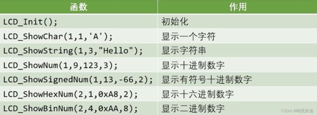
注意:LCD与数码管冲突。
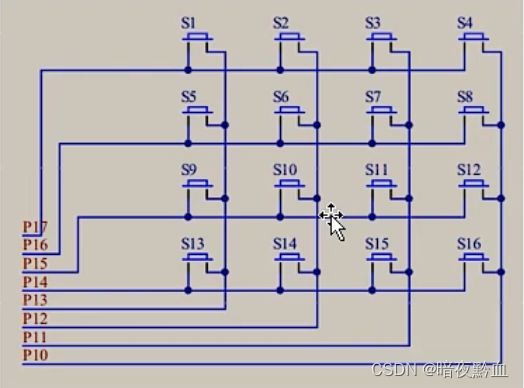
由图可知,P10至P13控制列,P14至P17控制行【可看作四排独立按键理解】
对比
以上两种扫描方式的共同特点:节省I/O口的数量
前提:因为矩阵键盘与步进电机(蜂鸣器)引脚冲突,为了避免蜂鸣器响,所以采取逐列扫描
难点:P1P2P3都是弱上拉工作模式,在上面的原理图中如果P1输出低电平,按键另一端连接VCC的话,检测时电流太大。因此另一端连接GND,检测P1口输入是否是低电平来判断按键是否被按下(个人理解)
根据上面的知识内容荣,就可以写出下面的矩阵键盘检测的
.h文件:
#ifndef __MATRIXKEY_H__
#define __MATRIXKEY_H__
unsigned char MatrixKey();
#endif
.c文件:
#include
#include "Delay.h"//定义中运用了Delay函数,因此需要加上头文件
/**
*@brief 检测矩阵键盘按键键码
*@param 无
*@retval KeyNumber 键码
*/
unsigned char MatrixKey(){
unsigned char KeyNumber = 0;
P1 = 0xFF;//全置1
P1_3 = 0;//第一列
if(P1_7 == 0){Delay(20); while(P1_7 == 0); Delay(20); KeyNumber = 1;}
if(P1_6 == 0){Delay(20); while(P1_6 == 0); Delay(20); KeyNumber = 5;}
if(P1_5 == 0){Delay(20); while(P1_5 == 0); Delay(20); KeyNumber = 9;}
if(P1_4 == 0){Delay(20); while(P1_4 == 0); Delay(20); KeyNumber = 13;}
P1 = 0xFF;
P1_2 = 0;//第二列
if(P1_7 == 0){Delay(20); while(P1_7 == 0); Delay(20); KeyNumber = 2;}
if(P1_6 == 0){Delay(20); while(P1_6 == 0); Delay(20); KeyNumber = 6;}
if(P1_5 == 0){Delay(20); while(P1_5 == 0); Delay(20); KeyNumber = 10;}
if(P1_4 == 0){Delay(20); while(P1_4 == 0); Delay(20); KeyNumber = 14;}
P1 = 0xFF;
P1_1 = 0;//第三列
if(P1_7 == 0){Delay(20); while(P1_7 == 0); Delay(20); KeyNumber = 3;}
if(P1_6 == 0){Delay(20); while(P1_6 == 0); Delay(20); KeyNumber = 7;}
if(P1_5 == 0){Delay(20); while(P1_5 == 0); Delay(20); KeyNumber = 11;}
if(P1_4 == 0){Delay(20); while(P1_4 == 0); Delay(20); KeyNumber = 15;}
P1 = 0xFF;
P1_0 = 0;//第四列
if(P1_7 == 0){Delay(20); while(P1_7 == 0); Delay(20); KeyNumber = 4;}
if(P1_6 == 0){Delay(20); while(P1_6 == 0); Delay(20); KeyNumber = 8;}
if(P1_5 == 0){Delay(20); while(P1_5 == 0); Delay(20); KeyNumber = 12;}
if(P1_4 == 0){Delay(20); while(P1_4 == 0); Delay(20); KeyNumber = 16;}
return KeyNumber;//返回键码
}
【上面的写法简单且容易理解】
用LCD液晶屏显示矩阵键盘键码
#include
#include "MatrixKey.h"
#include "LCD1602.h"
#include "Delay.h"
void main(){
LCD_Init();
LCD_ShowString(1,1,"Hello");//第一行显示Hello
while(1){
unsigned char key = MatrixKey();//检测键码
if(key){ //用if语句,防止key立马清零后显示0
LCD_ShowNum(2,1,key,2);
}
}
}
并且,可以由此写出
矩阵键盘密码锁
#include
#include "MatrixKey.h"
#include "LCD1602.h"
#include "Delay.h"
unsigned char i = 0;//i表示位数
unsigned char a = 0;//a表示正确与否
unsigned char KeyNumber;
unsigned char password[4] = {1,3,4,1};//密码
void main(){
LCD_Init();
LCD_ShowString(1,1,"Password:");
LCD_ShowString(2,1," ");
while(1){
KeyNumber = MatrixKey();//检测键码
if(i < 4){
if(KeyNumber>0 && KeyNumber<=10){ //当键码为0~10时,因为只显示一位数字,因此10即是0
if(KeyNumber == password[i]&&a<4){ //对应密码正确的话,a增加1
a++;
}
LCD_ShowNum(2,i+1,KeyNumber,1);
i++; //输入数字后,位数加1后移
}
}
/*if(KeyNumber == 11 && i >= 0){
i--;
LCD_ShowString(2,i+1," ");
}*/
if(KeyNumber == 12){//键码为12,表示确认按键
if(i == 4){//输入了4位
if(a == 4){
LCD_ShowString(1,11,"Right!");//当四位数字都正确时,输出Right
Delay(1000);
break;
}
else LCD_ShowString(1,11,"Error!");//否则,输出Error
Delay(600);
LCD_ShowString(1,11," ");
LCD_ShowString(2,1," ");
}
else { //数字不是四位时
LCD_ShowString(1,11,"False!"); //输出错误False
Delay(600);
LCD_ShowString(1,11," "); //清屏
LCD_ShowString(2,1," ");
}
i = 0; //数据重置
a = 0;
}
}
}
模式0:13位定时器/计数器
模式1:16位定时器/计数器
模式2:8位自动重装模式
模式3:两个8位计数器
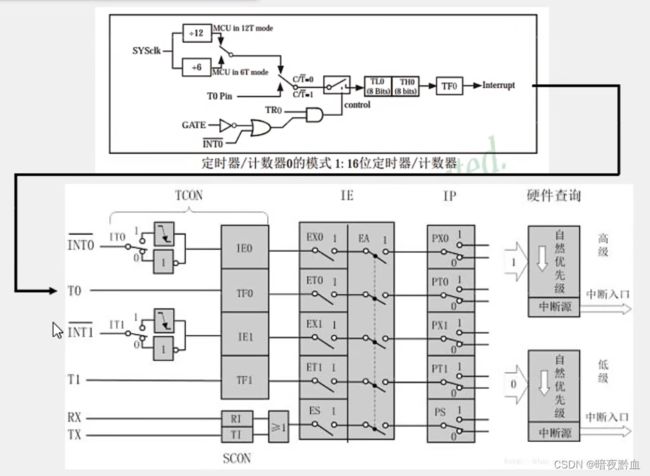
工作模式1框图:
时钟:
SYSclk:系统时钟,即晶振周期,本开发板上的晶振为11.0592MHz;
T0pin是外部引脚;
12T代表12分频,即12个周期一次输出;
C/T:如果是高电平1,那么就是计数器的功能,如果是低电平0,那就是计数器的功能。
计数单元:
TL0和TH0为一个16位的计数器,有两个字节,高字节为TH,低字节为TL;
当TL0和TH0最大时,就会向中断系统申请中断。
中断系统:
中断系统是为使CPU具有对外界紧急事件的实时处理能力而设置的。
如图所示过程:
当申请中断时,就会跳到中断程序,处理完后在返回主程序;
当加粗样式存在多个中断源时,CPU会根据优先级进行处理,首先响应高优先级的中断请求。
STC89C52中断资源:
因此,需要设置TCON(Timer Control)和TMOD寄存器来设置定时器
2.
M1为0,M0为1时,即为16位定时器,我们要用的模式;
C/T:控制定时器还是计数器功能;
GATE:门控端,控制是否由外部控制启动定时器
结合下图看
由图可以看,启动中断
IE中需要ET0置1,EA置1;
IP为设置中断优先级,可以不考虑,我们暂且置0,低优先级。
定时器的初始化:
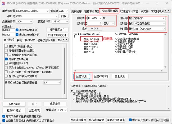
#include
/**
*@brief 定时器0初始化
*@param 无
*@retval 无
*/
void Timer0Init(void)
{
//由于TMOD不可寻址,因此需要用与&,或|来对单独一位设置
TMOD &= 0xF0; //把TMOD的第四位清零而高四位不变
TMOD |= 0x01;//把TMOD的最低位置一
TL0 = 0x66;//低四位
TH0 = 0xFC;//高四位
TF0 = 0;//清零
TR0 = 1;
//中断寄存器配置
ET0 = 1;
EA = 1;
PT0 = 0;
}
一秒定时:
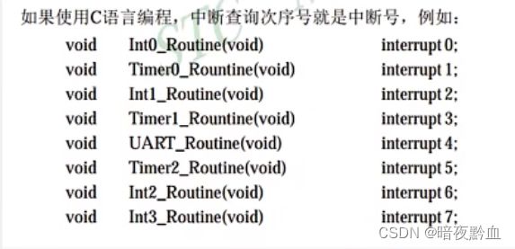
void Timer0_Routine() interrupt 1
{
static unsigned int count = 0;//静态变量
//重置
TL0 = 0x66;
TH0 = 0xFC;
count++;//每次中断加一
if(count >= 1000){
}
}
按键控制LED流水灯方向
#include
#include "Timer0.h"
#include "Delay.h"
unsigned char mode = 0;
void main(){
Timer0Init();
P2 = 0xFE;
while(1){//检测按键并改变模式
if(P3_1 == 0){
Delay(20);
while(P3_1 == 0);
Delay(20);
mode = 1;
}
if(P3_0 == 0){
Delay(20);
while(P3_0 == 0);
Delay(20);
mode = 0;
}
}
}
void Timer0_Routine() interrupt 1
{
static unsigned int count = 0;
TL0 = 0x66;
TH0 = 0xFC;
count++;
//流水灯代码
if(count >= 1000 && mode == 0){
P2 = (P2<<1) + 1;
if(P2 == 0xFF){
P2 = 0xFE;
}
count = 0;
}
if(count >= 1000 && mode == 1){
P2 = (P2>>1) + 0x80;
if(P2 == 0xFF){
P2 = 0x7F;
}
count = 0;
}
}
定时器计时
#include
#include "Timer0.h"
#include "LCD1602.h"
#include "Key.h"//独立按键检测模块
unsigned char hour=0,min=0,sec=0;//初始化
void main()
{
//初始化
LCD_Init();
Timer0Init();
LCD_ShowString(1,1,"Clock:");
while(1)
{
//显示时间
LCD_ShowNum(2,1,hour,2);
LCD_ShowNum(2,4,min,2);
LCD_ShowNum(2,7,sec,2);
switch(Key())//检测按键并选择时间加一
{
case 1:
hour++;
break;
case 2:
min++;
break;
case 3:
sec++;
break;
case 4://清零
hour = 0;
min = 0;
sec = 0;
break;
}
}
}
void Timer0_Routine() interrupt 1
{
static unsigned int count = 0;
TL0 = 0x66;
TH0 = 0xFC;
count++;
//时钟
if(count >= 1000){
count = 0;
sec++;
if(sec >= 60)
{
sec = 0;
min++;
if(min >= 60)
{
min = 0;
hour++;
if(hour >= 24)
{
hour = 0;
}
}
}
}
}
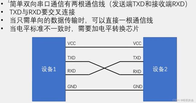
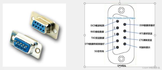
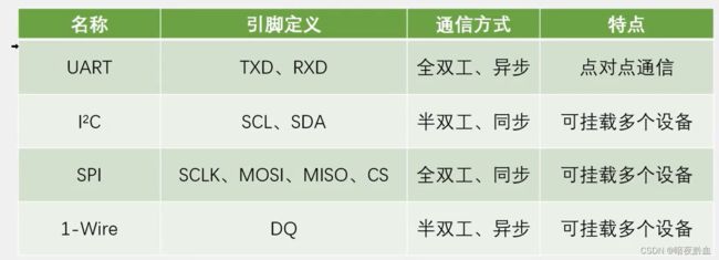
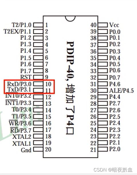
TXD(Transmit Exchange Data)发送,RXD(Receive External Data)接收,因此需要两根通信线。
电平标准是数据1和数据0的表达方式,是传输线缆中人为规定的电压与数据的对应关系,串口常用的电平标准有如下三种:
【TTL电平和 RS232电平传输距离有限,而RS485电平传输距离可以很远,千米级别】
STC89C52有1个UART
STC89C52的UART有四种工作模式:
模式0:同步移位寄存器
模式1:8位UART,波特率可变(常用)
模式2:9位UART,波特率固定
模式3:9位UART,波特率可变
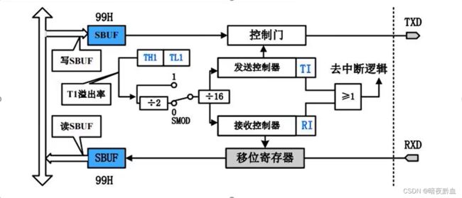
SBUF:串口数据缓存寄存器,物理上是两个独立的寄存器,但占用相同的地址。写操作时,写入的是发送寄存器(SBUF在等号左边),读操作时,读出的是接受寄存器(SBUF在等号右边)。
过程:
发送时,数据通过总线流入,通过定时器控制发送控制器来控制移位寄存器,将数据寄存到发送寄存器,同时触发中断,然后再通过总线发送出去,而速率通过定时器控制。接收类似。
SCON:
我们需要配置模式一:SM0为0,SM1为1;
不需要多机通信,因此SM2配为0;
REN:控制是否允许单片机接收数据,0为不允许;
TB8,RB8为9位数据,不是模式一的,因此不管,置0;
T1,R1标志位初始化给0;
PCON:
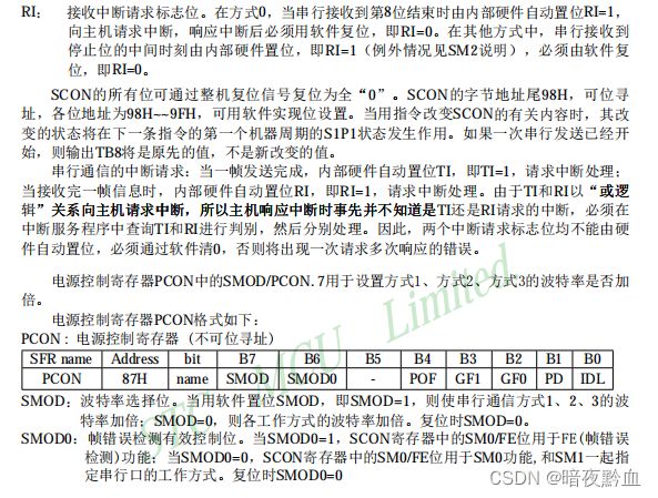
SMOD控制波特率是否加倍,不需要,因此给0;
SMOD0用于9位数据帧错误,模式一为8为数据,不需要,置0;
串口初始化
#include
void UART_Init(void) //[email protected]
{
SCON = 0x40; //只发
PCON |= 0x80;
//设置定时器模式8位自动重装
TMOD &= 0x0F;
TMOD |= 0x20;
//设置定时初值
TL1 = 0xF4;
TH1 = 0xF4;
ET0 = 0; //禁止定时器中断
EA = 1;
TR1 = 1; //启动定时器1
}
发送一个字节
void UART_SendByte(unsigned char Byte)
{
SBUF = Byte;
while(TI==0);//检测是否完成发送
TI=0;//重置复位
}
例子:电脑通过串口控制LED
#include
#include "Delay.h"
#include "UART.h"
unsigned char x;
void main()
{
UART_Init(); //初始化
while(1){
UART_SendByte(x);
Delay(1000); //延时一秒发送数据x
}
}
void UART_Routine() interrupt 4 //串口中断为interrupt 4
{
if(RI == 1) //如果是接收
{
x = SBUF; //更新x的值
P2 = ~x; //改变LED
RI = 0; //复位
}
if(TI == 1) //如果是发送,x每秒加一
{
P2 = ~x++; //改变LED,并x加一
}
}
LED点阵屏由若干个独立的LED组成,LED以矩阵的形式排列,以灯珠亮灭来显示文字,图片,视频等。LED点阵屏广泛应用于各种公共场合。
OE:输出使能,低电平有效【交线帽操作】
SRCLR:串行清零端
74HC595是串行输入并行输出的移位寄存器,可用3根线输入串行数据,8根线输出并行数据,多片级联后,可输出16位,24位,32位等,常用于I/O口扩展。
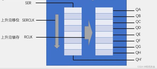
详情请看注释
#include
sbit RCK = P3^5; //RCLK上升沿锁存
sbit SCK = P3^6; //SERCLK上升沿移位
sbit SER = P3^4; //串行数据
/**
*@brief 74HC595写入一个字节
*@param 要写入的字节
*@retval 无
*/
void _74HC595_WriteByte(unsigned char Byte)
{
unsigned char i;
for(i = 0; i < 8; i++) //循环8次,移入一个字节
{
SER = Byte&(0x80>>i); //SER先送高位数字,SER赋值的数非0即1
SCK = 1; //上升沿————移位
SCK = 0; //下降沿————清零重置
}
RCK = 1; //上升沿————锁存
RCK = 0; //下降沿————清零重置
}
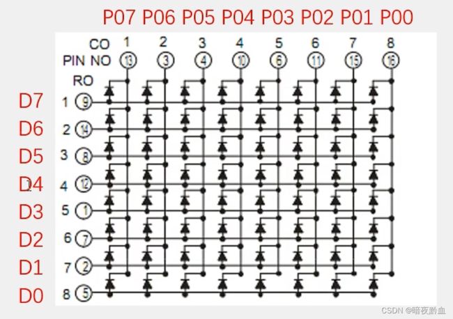
由上面引脚图可知,P0控制列,74HC595控制行。
因此:
#define column P0
/**
*@brief 矩阵屏初始化
*@param 无
*@retval 无
*/
void MatrixLED_Init()
{
SCK = 0;
RCK = 0;
}
/**
*@brief 矩阵屏显示一列数据
*@param x列,y行
*@retval 无
*/
void MatrixLED_Show(unsigned char x, y) //x轴控制列,y轴控制行
{
_74HC595_WriteByte(y); //控制行,高位在上,低位在下,高电平1亮
column = ~(0x80>>x); //控制列,高位在左、低位在右,低电平0亮
Delay(1); //延时
column = 0xFF; //清零,消影
}
然后,我们就可以用上面的MatrixLED_Show函数显示图形了。
动画即是不断在动的画,因此将画连续显示,就成了动画。我们可以利用上面的点阵屏显示函数,写一个循环语句以达成该目的。
#include
#include "MatrixLED.h"
unsigned char code Hellocartoon[] = {
0x00,0x00,0x00,0x00,0x00,0x00,0x00,0x00,
0xFF,0x08,0x08,0x08,0x08,0xFF,0x00,0x00,0x0E,0x15,0x15,0x15,0x0D,0x00,0x00,0xFF,
0x01,0x02,0x00,0xFF,0x01,0x02,0x00,0x00,0x0E,0x11,0x11,0x0E,0x00,0x00,0xFD,0x00,
0x00,0x00,0x00,0x00,0x00,0x00,0x00,0x00,
}; //Hello动画数组存储数据,开头与末尾个八个0x00,用来循环时可无缝衔接
void main()
{
unsigned char i, offset = 0, cnt = 0;
MatrixLED_Init(); //初始化
while(1)
{
for(i=0;i<8;i++)
{
MatrixLED_Show(i,Hellocartoon[i+offset]); //显示一个画面
}
cnt++; //cnt控制一张画面显示多久时间
if(cnt == 10)
{
cnt = 0;
offset++; //cnt达到10时,画面切换成下一帧,因为只是要画面左移,所以offset加一即可
if(offset > 40)
{
offset = 0; //当offset加到40(最大数量48-8)时,重置
}
}
}
}
动画数组数据因为运行时是不用改变的,放在RAM占用空间,因此可以加一个code(如代码所示),存到闪存flash
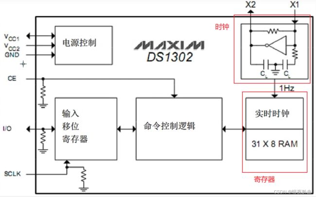
定时器时钟由于精度不高,占用CPU,因此通常不选择,而选择实时时钟芯片。
32.768kHz晶振精确,可以给出1Hz的稳定脉冲,称作石英钟
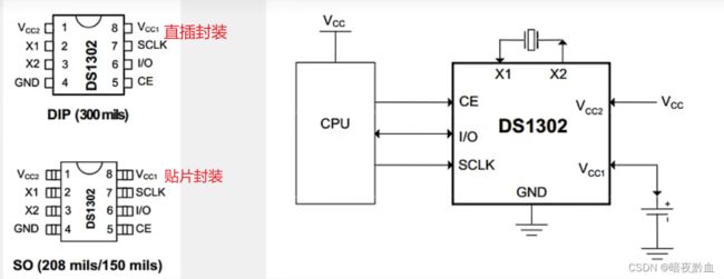
这里的CE,IO,SCLK与74HC595里的RCLK,SER,SERCLK是一样的,都是P3_5,P3_4,P3_6。因此实时时钟会与点阵屏冲突。
开发板上的原理图
可以看到,并没有备用电源,因此断电后始终无法继续走。
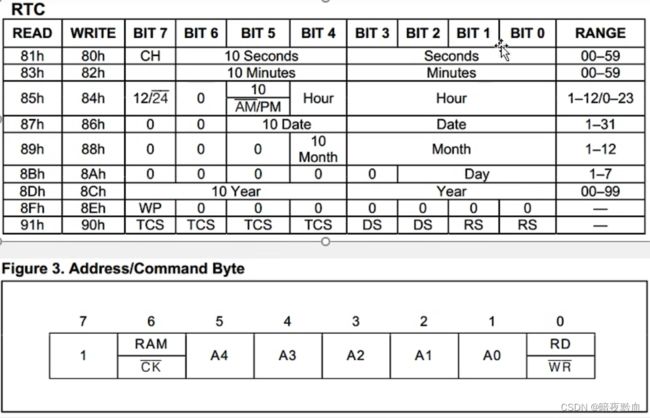
Seconds秒,Minutes分,Hour时,Date日期,Month月份,Day星期,Year年份
第一行的CH置1的话,时钟停止
倒数第二行中有一个WP,控制写保护
Address/Command Byte:命令字
由命令字表可以看到
第6位表示控制RAM还是时钟
第0位表示是否开启写保护(上头有横杠表示低电平有效)
命令字可以在RTC第一二列查到;
当电压为5V时,上升下降间隔时间最小为50ns,ns级别,单片机因此不用考虑
#include
sbit DS1302_SCLK = P3^6;
sbit DS1302_IO = P3^4;
sbit DS1302_CE = P3^5;
//写入
void DS1302_WriteByte(unsigned char Command, Date)
{
unsigned char i;
DS1302_CE = 1; //开启使能
for(i = 0; i < 8; i++)
{
DS1302_IO = Command&(0x01<<i); //命令字,0x01不断左移,逐个数字写入
DS1302_SCLK = 1; //上升沿移位
DS1302_SCLK = 0; //清零
}
for(i = 0; i < 8; i++)
{
DS1302_IO = Date&(0x01<<i); //要写入的数据也逐个写入
DS1302_SCLK = 1;
DS1302_SCLK = 0;
}
DS1302_CE = 0; //关闭使能
}
//读出
unsigned char DS1302_ReadByte(unsigned char Command)
{
unsigned char i, Date = 0x00;
Command |= 0x01; //读出的命令字最低位为1
DS1302_CE = 1; //开启使能
for(i = 0; i < 8; i++)
{
DS1302_IO = Command&(0x01<<i); //命令字
DS1302_SCLK = 0;
DS1302_SCLK = 1;
}
for(i = 0; i < 8; i++)
{
DS1302_SCLK = 1;
DS1302_SCLK = 0;
if(DS1302_IO){Date |= (0x01<<i);} 如果IO不为0,则存入1,以此办法读出数据
}
DS1302_IO = 0;
DS1302_CE = 0; //关闭使能
return Date;
}
时钟数据是以BCD码存储的
所以在显示时钟时需要将数据转化为十进制
因为上面的两个函数读出和写入时需要调用太多,太麻烦
因此,我们写一个DS1302_ReadTime函数直接读出时钟数据,一个DS1302_SetTime函数直接将时间写入时钟
#include
sbit DS1302_SCLK = P3^6;
sbit DS1302_IO = P3^4;
sbit DS1302_CE = P3^5;
//声明时间,方便后续书写
#define year 0x8C
#define day 0x8A
#define month 0x88
#define date 0x86
#define hour 0x84
#define minute 0x82
#define second 0x80
#define WP 0x8E
//初始时间
unsigned char Time[] = {23,12,13,12,0,0,3};
/**
*@brief 时钟初始化
*@param 无
*@retval 无
*/
void DS1302_Init(void)
{
DS1302_CE = 0;
DS1302_SCLK = 0;
}
/**
*@brief 写入对应时间
*@param Command命令字——对应时间地址(year,month...)
*@param Date数据——写入相应的时间数据
*@retval 无
*/
void DS1302_WriteByte(unsigned char Command, Date)
{
unsigned char i;
DS1302_CE = 1;
for(i = 0; i < 8; i++)
{
DS1302_IO = Command&(0x01<<i);
DS1302_SCLK = 1;
DS1302_SCLK = 0;
}
for(i = 0; i < 8; i++)
{
DS1302_IO = Date&(0x01<<i);
DS1302_SCLK = 1;
DS1302_SCLK = 0;
}
DS1302_CE = 0;
}
/**
*@brief 读出对应时间
*@param Command命令字——对应时间地址(year,month...)
*@retval Date返回时间数据
*/
unsigned char DS1302_ReadByte(unsigned char Command)
{
unsigned char i, Date = 0x00;
Command |= 0x01;
DS1302_CE = 1;
for(i = 0; i < 8; i++)
{
DS1302_IO = Command&(0x01<<i);
DS1302_SCLK = 0;
DS1302_SCLK = 1;
}
for(i = 0; i < 8; i++)
{
DS1302_SCLK = 1;
DS1302_SCLK = 0;
if(DS1302_IO){Date |= (0x01<<i);}
}
DS1302_IO = 0;
DS1302_CE = 0;
return Date;
}
/**
*@brief 将数组时间写入芯片
*@param 无
*@retval 无
*/
void DS1302_SetTime(void)
{
DS1302_WriteByte(WP,0x00); //关闭写保护
//年、月、日、时、分、秒、星期,依次写入数组里的时间
DS1302_WriteByte(year,Time[0]/10*16+Time[0]%10);
DS1302_WriteByte(month,Time[1]/10*16+Time[1]%10);
DS1302_WriteByte(date,Time[2]/10*16+Time[2]%10);
DS1302_WriteByte(hour,Time[3]/10*16+Time[3]%10);
DS1302_WriteByte(minute,Time[4]/10*16+Time[4]%10);
DS1302_WriteByte(second,Time[5]/10*16+Time[5]%10);
DS1302_WriteByte(day,Time[6]/10*16+Time[6]%10);
DS1302_WriteByte(WP,0x80); //打开写保护
}
/**
*@brief 将当前时间赋值给初始时间数组
*@param 无
*@retval 无
*/
void DS1302_ReadTime(void)
{
unsigned char temp; //暂存数据
依次将时钟时间赋给数组的时间
temp = DS1302_ReadByte(year);
Time[0] = temp/16*10+temp%16;
temp = DS1302_ReadByte(month);
Time[1] = temp/16*10+temp%16;
temp = DS1302_ReadByte(date);
Time[2] = temp/16*10+temp%16;
temp = DS1302_ReadByte(hour);
Time[3] = temp/16*10+temp%16;
temp = DS1302_ReadByte(minute);
Time[4] = temp/16*10+temp%16;
temp = DS1302_ReadByte(second);
Time[5] = temp/16*10+temp%16;
temp = DS1302_ReadByte(day);
Time[6] = temp/16*10+temp%16;
}
然后主函数
#include
#include "LCD1602.h"
#include "DS1302.h"
#include "Delay.h"
void main()
{
LCD_Init();
DS1302_Init();
LCD_ShowString(1,1," - - ");
LCD_ShowString(2,1," : : ");
DS1302_SetTime();
while(1)
{
DS1302_ReadTime(); //不断将时钟赋值给数组时间
//显示时间
LCD_ShowNum(1,1,Time[0],2);
LCD_ShowNum(1,4,Time[1],2);
LCD_ShowNum(1,7,Time[2],2);
LCD_ShowNum(2,1,Time[3],2);
LCD_ShowNum(2,4,Time[4],2);
LCD_ShowNum(2,7,Time[5],2);
LCD_ShowNum(2,13,Time[6],1);
}
}
进阶,可调时钟
#include
#include "LCD1602.h"
#include "DS1302.h"
#include "Delay.h"
#include "Key.h"
#include "Timer0.h"
void TimeShow(); //时间展示模式
void TimeSet(); //时间设置模式
//TimeSet里按键三四判断该月最大天数。输入月份、年份,输出天数
unsigned char JudgeDate(unsigned char month, year);
unsigned char mode,keynum,number,x;
void main()
{
//初始化
LCD_Init();
DS1302_Init();
Timer0Init();
//DS1302_SetTime();
LCD_ShowString(1,1," - - ");
LCD_ShowString(1,12,"Mode");
LCD_ShowString(2,1," : : ");
while(1)
{
keynum = Key(); //检测按键
LCD_ShowNum(1,16,mode,1); //显示模式
//按键一转换模式
if(keynum == 1)
{
if(mode == 0){mode = 1;}
else if(mode == 1)
{
mode = 0;
DS1302_SetTime();
}
}
//模式启动
if(mode == 0)
{
LCD_ShowString(2,10," "); //清除序号
TimeShow();
}
if(mode == 1){TimeSet();}
}
}
//时间显示函数
void TimeShow()
{
DS1302_ReadTime();
LCD_ShowNum(1,1,Time[0],2);
LCD_ShowNum(1,4,Time[1],2);
LCD_ShowNum(1,7,Time[2],2);
LCD_ShowNum(2,1,Time[3],2);
LCD_ShowNum(2,4,Time[4],2);
LCD_ShowNum(2,7,Time[5],2);
}
//调时间函数
void TimeSet()
{
//按键二切换年月日时分秒
if(keynum == 2)
{
//序号增加,越界清零
number++;
number%=6;
}
LCD_ShowNum(2,10,number+1,2); //显示年月日等序号顺序
//按键三增加
if(keynum == 3)
{
Time[number]++;
switch(number)
{
case 1: //月
if(Time[1]>12){Time[1]=1;}
break;
case 2: //日
if(Time[2]>JudgeDate(Time[1],Time[0]))
{Time[2]=1;}
break;
case 3: //时
if(Time[3]>23){Time[3]=0;}
break;
case 4: //分
if(Time[4]>59){Time[4]=0;}
break;
case 5: //秒
if(Time[5]>59){Time[5]=0;}
break;
}
}
//按键四减少
if(keynum == 4)
{
Time[number]--;
switch(number)
{
case 1: //月
if(Time[1]== 0){Time[1]=12;}
break;
case 2: //日
if(Time[2]== 0)
{Time[2]=JudgeDate(Time[1],Time[0]);}
break;
case 3: //时
if(Time[3]>23){Time[3]=23;}
break;
case 4: //分
if(Time[4]>59){Time[4]=59;}
break;
case 5: //秒
if(Time[5]>59){Time[5]=59;}
break;
}
}
//防止改变年月时日期超过最大天数
if(Time[2]>JudgeDate(Time[1],Time[0]))
{Time[2]=JudgeDate(Time[1],Time[0]);}
//展示更改时间
if(x == 0)
{
LCD_ShowNum(1,1,Time[0],2);
LCD_ShowNum(1,4,Time[1],2);
LCD_ShowNum(1,7,Time[2],2);
LCD_ShowNum(2,1,Time[3],2);
LCD_ShowNum(2,4,Time[4],2);
LCD_ShowNum(2,7,Time[5],2);
}
else //否则,对应位置清空,以达到闪烁效果
{
if(number < 3)
{
LCD_ShowString(1,number*3+1," ");
}
else LCD_ShowString(2,number*3-8," ");
}
}
//判断最大日期
unsigned char JudgeDate(unsigned char month, year)
{
unsigned char DateMax;
if(month==1||month==3||month==5||month==7
||month==8||month==10||month==12)
{DateMax = 31;} //31天月份
if(month==4||month==6||month==9||month==11)
{DateMax = 30;} //30天月份
if(month==2) //先判断2月,在判断闰年
{
if(year%4==0){DateMax=29;}
else DateMax=28;
}
return DateMax; //返回最大日期
}
//中断,计时,用来闪烁的周期——1s
void Timer0_Routine() interrupt 1
{
static unsigned int count = 0;
TL0 = 0x66;
TH0 = 0xFC;
count++;
if(count>=300)
{
count = 0;
x = ~x;
}
}
#include
#include "LCD1602.h"
#include "DS1302.h"
#include "Delay.h"
#include "Key.h"
#include "Timer0.h"
#include "Nixie.h"
#include "MatrixKey.h"
#include "MatrixLED.h"
void mode0();
void mode1();
void mode2();
void mode3();
void clarm();
void showtime();//时分秒分开显示,后续模式二编写闪烁比较方便
void showhour();
void showminute();
void showsecond();
unsigned char keynum,key_last, mode, lastmode, x, y;
//按键keynum,模式mode,“-”闪烁判断x,时间数字闪烁判断y
unsigned char code clarm_p[] = {
0x00,0x00,0x00,0x00,0x00,0x00,0x00,0x00,
0x00,0x00,0x00,0xFB,0xFB,0x00,0x00,0x00,
0x00,0x00,0x00,0xFB,0xFB,0x00,0x00,0x00,//?????
0x00,0x00,0x00,0x00,0x00,0x00,0x00,0x00,
0x00,0x00,0x00,0xFB,0xFB,0x00,0x00,0x00,//?????
0x00,0x00,0x00,0xFB,0xFB,0x00,0x00,0x00,
0x00,0x00,0x00,0x80,0x80,0x00,0x00,0x00,//????
0x00,0x00,0x00,0x80,0x80,0x40,0x20,0x00,
0x00,0x00,0x00,0x80,0x80,0x40,0x20,0x18,
0x00,0x00,0x00,0x80,0x80,0x42,0x24,0x18,
0x00,0x00,0x00,0x81,0x81,0x42,0x24,0x18,
0x00,0x04,0x02,0x81,0x81,0x42,0x24,0x18,
0x18,0x04,0x02,0x81,0x81,0x42,0x24,0x18,
0x18,0x24,0x42,0x81,0x81,0x42,0x24,0x18,
0x18,0x24,0x42,0x81,0x81,0x42,0x24,0x18,//????
};
void main()
{
DS1302_Init();//初始化
Timer0Init();
MatrixLED_Init();
while(1)
{
keynum = MatrixKey();//读取按键
if(keynum == 4 && key_last == 0)mode = 1; //切换模式
if(keynum == 8 && key_last == 0)
{
DS1302_SetTime();//将数组时间写入芯片,更新模式一所调时间
mode = 2;
}
if(keynum == 9 && key_last == 0)mode = 3;
switch(mode)//启动模式
{
case 0:
mode0();//初始模式
break;
case 1:
mode1();//调节模式
break;
case 2:
mode2();//计时模式
break;
case 3:
mode3();//设置闹钟模式
DS1302_ReadTime();//不停更新数组时间,使得在调闹钟的时候,时钟依旧在走
MatrixLED_Init();
break;
case 4:
clarm();//闹钟
DS1302_ReadTime();//不停更新数组时间,使得在调闹钟的时候,时钟依旧在走
break;
}
key_last = keynum;
}
}
void mode0()
{
if(x == 1)
{
nixie(3,11);
nixie(6,11);
}
nixie(1,1);nixie(2,2);nixie(4,0);nixie(5,0);nixie(7,0);nixie(8,0);
}
unsigned char temp;
void mode1()
{
//加
if(keynum==1 && key_last == 0)//加小时,越界清零
{
Time[3]++;
if(Time[3]>23)
{
Time[3] = 0;
}
}
if(keynum==2 && key_last == 0)//加分钟,越界清零
{
Time[4]++;
if(Time[4]>59)
{
Time[4] = 0;
}
}
if(keynum==3 && key_last == 0)//加秒,越界清零
{
Time[5]++;
if(Time[5]>59)
{
Time[5] = 0;
}
}
//减
if(keynum==5 && key_last == 0)//减小时,越界清零
{
Time[3]--;
if(Time[3]>23)
{
Time[3] = 23;
}
}
if(keynum==6 && key_last == 0)//减分钟,越界清零
{
Time[4]--;
if(Time[4]>59)
{
Time[4] = 59;
}
}
if(keynum==7 && key_last == 0)//减秒,越界清零
{
Time[5]--;
if(Time[5]>59)
{
Time[5] = 59;
}
}
//显示横杠-
nixie(3,11);nixie(6,11);
//显示数字
if(keynum != 0)//暂存按键数据
{
temp = keynum;
}
//闪烁
if(y == 1)
{
showtime();
}
else
{
if(temp == 1||temp == 5)
{
showminute();
showsecond();
}
else if(temp == 2||temp == 6)
{
showhour();
showsecond();
}
else if(temp == 3||temp == 7)
{
showhour();
showminute();
}
else showtime();
}
}
void mode2()
{
DS1302_ReadTime();//更新数组时间
MatrixLED_Init();//因为加下来P0要置0,所以得先将点阵屏初始化
if(x == 1) //周期显示横杠-
{
nixie(3,11);
nixie(6,11);
}
showtime();
}
unsigned char clarm_hour,clarm_minute,clarm_second;//闹钟时分秒
void mode3()
{
//显示闹钟时间
nixie(3,11);nixie(6,11);//显示横杠-
nixie(1,clarm_hour/10);nixie(2,clarm_hour%10);//时
nixie(4,clarm_minute/10);nixie(5,clarm_minute%10);//分
nixie(7,clarm_second/10);nixie(8,clarm_second%10);//秒
//加
if(keynum==1 && key_last == 0)//加小时,越界清零
{
clarm_hour++;
if(clarm_hour>23)
{
clarm_hour = 0;
}
}
if(keynum==2 && key_last == 0)//加分钟,越界清零
{
clarm_minute++;
if(clarm_minute>59)
{
clarm_minute = 0;
}
}
if(keynum==3 && key_last == 0)//加秒,越界清零
{
clarm_second++;
if(clarm_second>59)
{
clarm_second = 0;
}
}
//减
if(keynum==5 && key_last == 0)//减小时,越界清零
{
clarm_hour--;
if(clarm_hour>23)
{
clarm_hour = 23;
}
}
if(keynum==6 && key_last == 0)//减分钟,越界清零
{
clarm_minute--;
if(clarm_minute>59)
{
clarm_minute = 59;
}
}
if(keynum==7 && key_last == 0)//减秒,越界清零
{
clarm_second--;
if(clarm_second>59)
{
clarm_second = 59;
}
}
}
unsigned char p_num, i, count3;//p_num图像帧数
void clarm() //闹钟
{
for(i = 0; i < 8; i++)
{
MatrixLED_Show(i,clarm_p[i+p_num]);//显示一帧
}
if(count3 > 200)
{
count3 = 0;
p_num += 8; //显示下一帧
if(p_num > 136)p_num = 48; //超出时重置
}
}
void showtime() //显示时间
{
showhour();
showminute();
showsecond();
}
void showhour()
{
nixie(1,Time[3]/10);nixie(2,Time[3]%10);//时
}
void showminute()
{
nixie(4,Time[4]/10);nixie(5,Time[4]%10);//分
}
void showsecond()
{
nixie(7,Time[5]/10);nixie(8,Time[5]%10);//秒
}
void Timer0_Routine() interrupt 1
{
static unsigned int count1 = 0, count2 = 0;
TL0 = 0x66;
TH0 = 0xFC;
count1++;
count2++;
if(count1 >= 500)
{
count1 = 0;
x = !x;
}
if(count2 >= 250)
{
count2 = 0;
y = !y;
}
if(Time[3]==clarm_hour&&
Time[4]==clarm_minute&&
Time[5]==clarm_second)//判断是否达到预定时间,达到就切换成闹钟
{
mode = 4;
}
count3++;
}