Vulkan vertex buffer绑定过程
代码实战
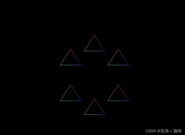
我们用indirect draw绘制6个不同位置的三角形,效果如下:
重点:具备layout(location = xx) in 格式描述的资源就是 vertex buffer。
vs shader如下, inPos,inColor,instancePos则是vertext buffer数据:
//vs
#version 450
layout (location = 0) in vec3 inPos;
layout (location = 1) in vec3 inColor;
layout (location = 2) in vec3 instancePos;

layout(location = 0) out vec3 fragColor;

void main() {
    gl_Position = vec4(inPos, 1.0) + vec4(instancePos, 1.0);
    gl_Position.y = -gl_Position.y;
    fragColor = inColor;
}
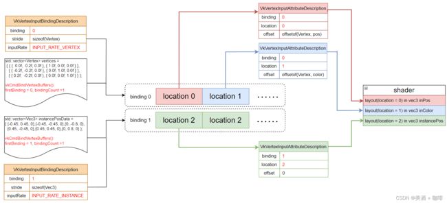
vertex buffer的布局分布如下:
- location 0的inPos、location 1的inColor使用binding 0
- location 2的instancePos使用binding 1
代码侧调用vkCmdBindVertexBuffers告诉gpu从哪个binding位置读取顶点数据(即vkCmdBindVertexBuffers的firstBinding参数,与shader中layout的binding完全没关系,这点在后面的descriptor章节再讲)。
gpu知道了从哪里读数据,但是怎么读?这就用到了VkVertexInputBindingDescription和 VkVertexInputAttributeDescription两个结构体,它们在创建pipeline时被使用。
结构体详细说明:
typedef struct VkVertexInputBindingDescription {
    uint32_t             binding;   //数据绑定位置
    uint32_t             stride;    //连续两个数据之间的间隔
    VkVertexInputRate    inputRate; //两种方式, per-vertex:对每个顶点输入, per-instance:对每个实例输入
} VkVertexInputBindingDescription;

typedef struct VkVertexInputAttributeDescription {
    uint32_t    location;    //在shader中location一致
    uint32_t    binding;     //数据绑定位置
    VkFormat    format;      //数据格式
    uint32_t    offset;      //属性相对于顶点开始位置的偏移
} VkVertexInputAttributeDescription;
这里需要注意的是VkVertexInputBindingDescription::inputRate, 它代表两种数据输入:
- VK_VERTEX_INPUT_RATE_VERTEX:per-vertex,按图元的定点数分配
- VK_VERTEX_INPUT_RATE_INSTANCE:per-instance,按图元数分配
本例画6个三角形,对于编号i的三角形,会读取顶点数据vertices[0],vertices[1],vertices[2]以及中心点位置instancePosData[i]。
本例完整代码说明:
/* {inPosition, inColor}*/
struct Vertex {
    vec3 pos;
    vec3 color;
}
// vertex data of triangle
std::vector vertices = {
    { {  0.0f,  0.2f, 0.0f }, { 1.0f, 0.0f, 0.0f } },
    { { -0.2f, -0.2f, 0.0f }, { 0.0f, 1.0f, 0.0f } },
    { { 0.2f,  -0.2f, 0.0f }, { 0.0f, 0.0f, 1.0f } },
};
// 6 triangle instance center point postion
std::vector instancePosData = {
    {-0.45, 0.45, 0},{-0.45, -0.45, 0},{0, -0.8, 0},
    {0.45, -0.45, 0},{0.45, 0.45, 0},{0, 0.8, 0},
};

//create vertex buffer
VkDeviceSize vertexBufferSize = vertices.size() * sizeof(Vertex);
VkDeviceSize instancePosBufferSize = instancePosData.size() * sizeof(Vec3);

createBuffer(
        VK_BUFFER_USAGE_VERTEX_BUFFER_BIT | VK_BUFFER_USAGE_TRANSFER_DST_BIT,
        VK_MEMORY_PROPERTY_HOST_VISIBLE_BIT | VK_MEMORY_PROPERTY_DEVICE_LOCAL_BIT,
        &vertexBuffer, &vertexMemory,
        vertexBufferSize, vertices.data());

createBuffer(
    VK_BUFFER_USAGE_VERTEX_BUFFER_BIT | VK_BUFFER_USAGE_TRANSFER_DST_BIT,
    VK_MEMORY_PROPERTY_HOST_VISIBLE_BIT | VK_MEMORY_PROPERTY_DEVICE_LOCAL_BIT,
    &instancePosBuffer, &instancePosMemory,
    instancePosBufferSize,instancePosData.data());

VkDeviceSize offsets[] = {0};
//三角形顶点位置、颜色数据从binding 0读取
vkCmdBindVertexBuffers(
    commandBuffer,
    0,    // firstBinding
    1,    // bindingCount
    &vertexBuffer,
    offsets);

//三角形的中心点位置从binding 1读取
vkCmdBindVertexBuffers(
    commandBuffer,
    1,    // firstBinding
    1,    // bindingCount
    &instancePosBuffer,
    offsets);

// 读取顶点的方式、以及顶点数据布局传入graphicsPipelineCreateInfo
std::vector bindingDescription = {
    {.binding=0, .stride=sizeof(Vertex), .inputRate = VK_VERTEX_INPUT_RATE_VERTEX},   //逐顶点方式获取三角形顶点数据
    {.binding=1, .stride=sizeof(Vec3), .inputRate = VK_VERTEX_INPUT_RATE_INSTANCE}    //逐实例方式获取三角形位置数据
};
std::vector attributeDescriptions =
{
    {.binding = 0, .location = 0, .format = VK_FORMAT_R32G32B32_SFLOAT, .offset = offsetof(Vertex, pos)},   // inPos: binding 0, location 0
    {.binding = 0, .location = 1, .format = VK_FORMAT_R32G32B32_SFLOAT, .offset = offsetof(Vertex, color)}, // inColor: binding 0, location 1
    {.binding = 1, .location = 2, .format = VK_FORMAT_R32G32B32_SFLOAT, .offset = 0}    // instancePos: binding 1, location 2
}
...
vkPipelineVertexInputStateCreateInfo.pVertexBindingDescriptions = bindingDescription.data();
vkPipelineVertexInputStateCreateInfo.pVertexAttributeDescriptions = attributeDescriptions.data();
...
vkGraphicsPipelineCreateInfo.pVertexInputState = &vkPipelineVertexInputStateCreateInfo;
上面从代码到shader的vertex buffer数据绑定过程可以归纳成这张图:
这篇文章对vertext buffer的处理逻辑讲的很详细,可以扩展阅读一下:
https://github.com/KhronosGroup/Vulkan-Guide/blob/main/chapters/vertex_input_data_processing.adoc


