MATLAB - 双连杆机械臂逆运动学的推导及应用
系列文章目录
前言
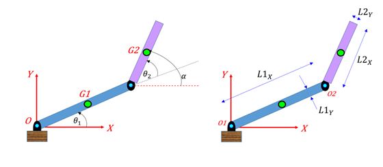
本示例展示了如何使用 MATLAB® 和 Symbolic Math Toolbox™ 对双连杆机械臂推导和应用逆运动学。
该示例以符号方式定义关节参数和末端执行器位置,计算正向和逆向运动学解法并将其可视化,同时求出系统雅各布系数,这对模拟机械臂的运动非常有用。
一、步骤 1:定义几何参数
将机器人的连杆长度、关节角度和末端执行器位置定义为符号变量。
syms L_1 L_2 theta_1 theta_2 XE YE指定机器人连杆长度的数值。
L1 = 1;
L2 = 0.5;
二、步骤 2:定义末端执行器的 X 和 Y 坐标
将末端执行器的 X 和 Y 坐标定义为关节角度 ![]() 的函数。
的函数。
XE_RHS = L_1*cos(theta_1) + L_2*cos(theta_1+theta_2)![]()
YE_RHS = L_1*sin(theta_1) + L_2*sin(theta_1+theta_2)![]()
将符号表达式转换为 MATLAB 函数。
XE_MLF = matlabFunction(XE_RHS,'Vars',[L_1 L_2 theta_1 theta_2]);
YE_MLF = matlabFunction(YE_RHS,'Vars',[L_1 L_2 theta_1 theta_2]);
三、步骤 3:计算正运动学并将其可视化
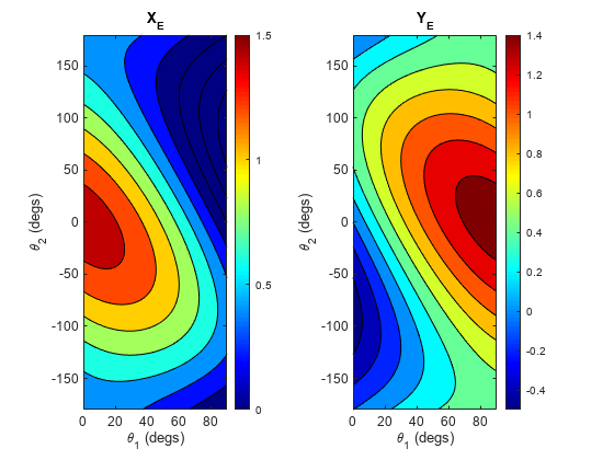
前向运动学将关节角度转换为末端执行器位置: ![]() 。给定具体的关节角度值,使用前向运动学计算末端执行器位置。
。给定具体的关节角度值,使用前向运动学计算末端执行器位置。
指定关节角度的输入值为 ![]() 。
。
t1_degs_row = linspace(0,90,100);
t2_degs_row = linspace(-180,180,100);
[tt1_degs,tt2_degs] = meshgrid(t1_degs_row,t2_degs_row);
将角度单位从度转换为弧度。
tt1_rads = deg2rad(tt1_degs);
tt2_rads = deg2rad(tt2_degs);
分别使用 MATLAB 函数 XE_MLF 和 YE_MLF 计算 X 和 Y 坐标。
X_mat = XE_MLF(L1,L2,tt1_rads,tt2_rads);
Y_mat = YE_MLF(L1,L2,tt1_rads,tt2_rads);
使用辅助函数 plot_XY_given_theta_2dof 可视化 X 和 Y 坐标。
plot_XY_given_theta_2dof(tt1_degs,tt2_degs,X_mat,Y_mat,(L1+L2))四、步骤 4:计算逆运动学
逆运动学将末端执行器的位置转换为关节角度: ![]() 。根据正向运动学方程求出逆向运动学。
。根据正向运动学方程求出逆向运动学。
定义正向运动学方程。
XE_EQ = XE == XE_RHS;
YE_EQ = YE == YE_RHS;
求解 θ 1 和 θ 2 .
S = solve([XE_EQ YE_EQ], [theta_1 theta_2])S = struct with fields:
theta_1: [2x1 sym]
theta_2: [2x1 sym]结构 S 表示 θ1 和 θ2 的多个解。显示 θ1 的一对解。
simplify(S.theta_1)显示 θ2 的一对解。
simplify(S.theta_2)将解法转换为稍后可以使用的 MATLAB 函数。函数 TH1_MLF 和 TH2_MLF 表示逆运动学。
TH1_MLF{1} = matlabFunction(S.theta_1(1),'Vars',[L_1 L_2 XE YE]);
TH1_MLF{2} = matlabFunction(S.theta_1(2),'Vars',[L_1 L_2 XE YE]);
TH2_MLF{1} = matlabFunction(S.theta_2(1),'Vars',[L_1 L_2 XE YE]);
TH2_MLF{2} = matlabFunction(S.theta_2(2),'Vars',[L_1 L_2 XE YE]);
五、步骤 5:计算并展示逆运动学
使用逆运动学计算 θ1 和 θ2。
定义 X 和 Y 坐标的网格点。
[xmat,ymat] = meshgrid(0:0.01:1.5,0:0.01:1.5);分别使用 MATLAB 函数 TH1_MLF{1} 和 TH2_MLF{1} 计算角度 θ1 和 θ2。
tmp_th1_mat = TH1_MLF{1}(L1,L2,xmat,ymat);
tmp_th2_mat = TH2_MLF{1}(L1,L2,xmat,ymat);
将角度单位从弧度转换为度。
tmp_th1_mat = rad2deg(tmp_th1_mat);
tmp_th2_mat = rad2deg(tmp_th2_mat);
某些输入坐标,如 (X,Y) = (1.5,1.5),超出了末端效应器的可触及工作空间。逆运动学求解会产生一些需要修正的虚θ 值。修正虚θ 值。
th1_mat = NaN(size(tmp_th1_mat));
th2_mat = NaN(size(tmp_th2_mat));

tf_mat = imag(tmp_th1_mat) == 0;
th1_mat(tf_mat) = real(tmp_th1_mat(tf_mat));

tf_mat = imag(tmp_th2_mat) == 0;
th2_mat(tf_mat) = real(tmp_th2_mat(tf_mat));
使用辅助函数 plot_theta_given_XY_2dof 将角度 θ1 和 θ2 可视化。
plot_theta_given_XY_2dof(xmat,ymat,th1_mat,th2_mat)步骤 6:计算系统雅各布
系统雅各布的定义是
the_J = jacobian([XE_RHS YE_RHS],[theta_1 theta_2])通过使用系统雅各布 J 及其摩尔-彭罗斯伪逆 J+,可以将关节速度与末端执行器速度联系起来,也可以反过来将末端执行器速度与关节速度联系起来:
您还可以将雅各比的符号表达式转换为 MATLAB 功能块。通过将多个航点定义为 Simulink® 模型的输入,模拟机器人在轨迹上的末端执行器位置。Simulink 模型可根据到达轨迹中每个航点的关节角度值计算运动轮廓。更多详情,请参阅 "2 连杆机械臂的逆运动学 "和 "刚体动力学教学"。
七、辅助函数
function plot_theta_given_XY_2dof(X_mat,Y_mat,theta_1_mat_degs,...
                                  theta_2_mat_degs)

xlab_str = 'X (m)';
ylab_str = 'Y (m)';

figure;
hax(1) = subplot(1,2,1);
   contourf(X_mat, Y_mat, theta_1_mat_degs);
      clim(hax(1), [-180 180]);
      colormap(gca,'jet'); colorbar
      xlabel(xlab_str, 'Interpreter', 'tex');
      ylabel(ylab_str, 'Interpreter', 'tex');
      title(hax(1), '\theta_1', 'Interpreter', 'tex')
      axis('equal')
hax(2) = subplot(1,2,2);
   contourf(X_mat, Y_mat, theta_2_mat_degs);
      clim(hax(2), [-180 180]);
      colormap(gca,'jet'); colorbar
      xlabel(xlab_str, 'Interpreter', 'tex');
      ylabel(ylab_str, 'Interpreter', 'tex');
      title(hax(2), '\theta_2', 'Interpreter', 'tex')
      axis('equal')

end


function plot_XY_given_theta_2dof(theta_1_mat_degs,theta_2_mat_degs,...
                                  X_mat,Y_mat,a_cmax)

xlab_str = '\theta_1 (degs)';
ylab_str = '\theta_2 (degs)';

figure;
hax(1) = subplot(1,2,1);
   contourf(theta_1_mat_degs, theta_2_mat_degs, X_mat);
      clim(hax(1), [0 a_cmax]);
      colormap(gca,'jet'); colorbar
      xlabel(xlab_str, 'Interpreter', 'tex');
      ylabel(ylab_str, 'Interpreter', 'tex');
      title(hax(1), 'X_E', 'Interpreter', 'tex')
hax(2) = subplot(1,2,2);
   contourf(theta_1_mat_degs, theta_2_mat_degs, Y_mat);
      clim(hax(1), [0 a_cmax]);
      colormap(gca,'jet'); colorbar
      xlabel(xlab_str, 'Interpreter', 'tex');
      ylabel(ylab_str, 'Interpreter', 'tex');
      title(hax(2), 'Y_E', 'Interpreter', 'tex')

end


