JACK——PaintRobot Exercise1
Exercise 1
Make a basic robot agent that contains a Java method that prints a message to indicate that the robot is painting a part.
The aim of this exercise is to demonstrate how to build, compile and run a JACK program using the JACK Development Environment (JDE). Consequently, no agent-oriented programming concepts other than agent creation are involved.
Note: The practicals will make use of the design tool to produce design diagrams and to create initial skeleton type definitions for the application. The JDE supports multiple ways to add detail to the type definitions. However, to avoid confusion during the practicals we will always use the Edit as JACK File option to add type definition details.
1. Make sure that CLASSPATH is set to include jack.jar and the root path for your application.
2. In a new directory (called ex1) start the JDE using the following command:
java -Xmx90m aos.main.Jack
3. Create a new project as follows:
- Left-click on the File menu at the top left corner of the screen.
- Left-click on New Project.
- A New Project File dialog box will appear.
- Name the project file PaintRobot and click on the New button. The project file suffix (.prj) will be added automatically.
- The New Project File dialog box will close and return the user to the JDE screen.
- In the top left corner of the browser window, the name of the new project will appear in red text.
4. We will now develop our application using the design tool. In this application we will develop the following types of diagrams:
- A top level agent diagram which includes the details of messages sent/handled by an agent.
- An agent-capability hierarchy diagram for each agent.
- A Data-Event-Plan (DEP) diagram for each capability.
Note that when we add new components to a design diagram, the skeleton for the type definition is automatically created and added to the browser. Links created between components on the design canvas result in the corresponding declarations being added to the type definitions in the browser. Removing a link from a design diagram removes the link from the underlying model and the change will be reflected in the browser. Removing a component from the design diagram does not remove it from the underlying model. It will still exist in the browser and can be dragged back on to the design canvas to view its relationships with other components in the diagram.
5. Create the top level agent diagram using the design tool.
- To access the design tool, right-click on the Design Views folder in the JDE. A pop-up menu will appear.
- Select Add New Design View from the menu. A pop-up dialog box will appear requesting a name for the design diagram.
- Give the design a name (Robot_AD) and click on the Add New button.
- The design tool canvas will appear. Left-click on the Open design palette button on the design tool menu bar.
- Drag the Agent icon from the design tool palette to the design tool canvas.
- Fill in the pop-up dialog box with details of the Robot agent. Make sure that the Robot agent is in a package called robot. Click on the Add New button. (The agent will now be displayed in the browser in the Agent Types folder inside the Agent Model.)
- You can choose to be in either Selection mode or Link mode. To enter Selection mode, click the Change to selection mode button on the design tool tool bar (the Change to selection mode button displays an arrow icon). In Selection mode, you can click on entities on the canvas and change their location on the diagram. Selected entities or links can also be removed by first selecting them, then pressing the Delete selected objects button. The Delete selected objects button is the button displaying a cross icon. To enter Link mode, click on the Change to link mode button (the Change to link mode button displays a diagonal line). In Link mode you can make connections between the entities on your diagram. Note that the direction of a link is significant.
6. In the browser, edit the Robot agent by right-clicking on the robot agent and selecting Edit as JACK file. Add a Java method called paintPart() that contains the statement
System.out.println("Painting part now").
Close the robot agent file to ensure that there are no conflicts between editing the file in the JDE browser and as a JACK file. In the editor window of the robot agent file, click the Save button and then the Close button.
7. Use the browser to add the main program. This is added in the Other Files folder at the top level of the browser hierarchy. Right-click on the Other Files folder and select Add New File from the pop-up menu. Add the code for the main program in the Edit File window which appears. Save the main program with the name Program.java. The following main program can be used to test the paint robot:
import robot.Robot;
public class Program {
public static void main( String args[] ) {
Robot robot1 = new Robot("robbie");
robot1.paintPart();
System.exit(0);
}
}
8. Save the project. This can be achieved by selecting the Save Project option from the File menu in the top left hand corner of the JDE.
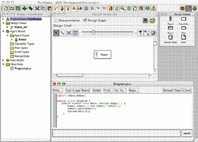
The JDE window should look similar to the following:
Figure 1: The JDE window with project browser, Robot_AD design, design palette and Program.java windows
9. Compile and run the program within the JDE.
- Click on the Tools menu and select Compiler Utility from the drop-down menu.
- Click on the Compile Application tab and click the Compile button. If there are any errors, they can be viewed in the Output/Errors tab in the Compiler Utility.
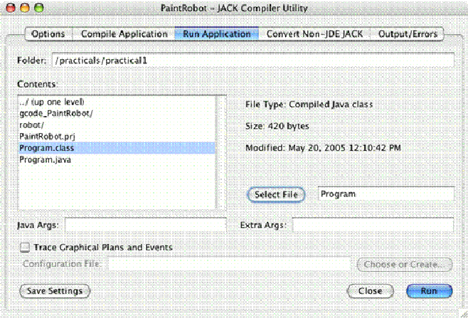
- When you have successfully compiled the application, click on the Run Application tab in the Compiler Utility. Click on Program.class from the contents window and then click on the Select File button. The Run button can then be selected to start running the program.
Figure 2: The Run Application tab of the Compiler Utility
运行结果:Painting part now

