Build the Hack CPU with Verilog
Build the Hack CPU with Verilog
陈硕 2009-04-18
http://blog.csdn.net/Solstice giantchen_AT_gmail.com
最近手痒,买了一本《计算机系统要素:从零开始构建现代计算机》http://www.china-pub.com/33880,把书中讲到的Hack CPU用Verilog实现了一把。
原书在Amazon的页面是http://tinyurl.com/cc6582 《The Elements of Computing Systems: Building a Modern Computer from First Principles》。这本书除了讲CPU,还讲了数字逻辑、虚拟机、编译器等一些有意思的内容,中文翻译得也不错。
1 Hack CPU介绍
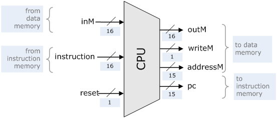
Hack是一个16-bit Harvard结构的CPU,指令和数据分开存放。数据总线是16-bit,地址总线是15-bit,只有三个寄存器A、D和PC,其中A和D都是16-bit,PC是15-bit。指令长度均为16-bit,每条指令都能在单周期内完成。从书的配套网站http://www1.idc.ac.il/tecs/plan.html 可下载讲义及部分章节,第五章讲了Hack CPU的设计,可以下载来看一看。这是Hack的接口框图:
module cpu(clk, nrst, inst_addr, inst, rdata, wdata, data_addr, we);
input clk, nrst;
input[15:0] inst; // instruction
input[15:0] rdata; // inM
output[14:0] inst_addr; // pc
output[14:0] data_addr; // addressM
output[15:0] wdata; // outM
output we; // writeM
endmodule
代码1:Hack CPU的接口
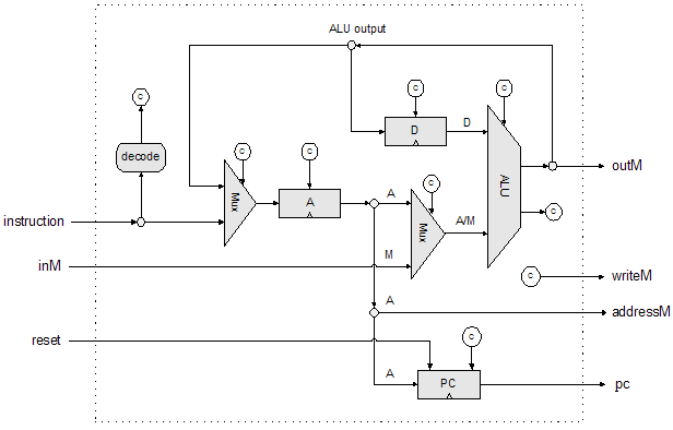
书中给出的实现框图:
Hack CPU可以用几十块74 TTL搭出来,不过得更改时序以适应异步SRAM的读写。它的复杂度可能还比不上一般大学本科的《微机原理》课程中要求学生实现的CPU。其实,实现一个能自动执行指令的数字电路比想象中简单多了,很多事情就是这样,一开始看上去很难,一旦上手去做,捅破了那层窗户纸,会发现其实做个能玩的出来也没那么困难。操作系统、编译器、CPU莫不如此。
下面分几步把Hack CPU造出来。
2 实现Hack CPU
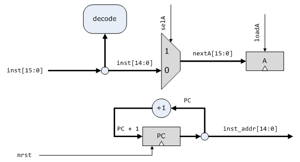
2.1 执行A指令,PC递增
Hack有两种类型的指令,A指令和C指令,A指令非常简单,它把指令的低15位存入寄存器A。我们先实现A指令,它的格式是:
指令的最高位是0,低15位是寄存器A的设置值。
module cpu(/* ... /*);
// 接口同“代码1”
reg[14:0] pc;
reg[15:0] a;
wire load_a = !inst[15];
wire sel_a = inst[15];
wire[14:0] next_pc = pc + 15'b1;
wire[15:0] next_a = sel_a ? 16b’x : {1'b0, inst[14:0]};
assign inst_addr = pc;
always @(posedge clk)
if (!nrst) // 同步清零
pc <= 15'b0;
else
pc <= next_pc;
always @(posedge clk)
if (load_a)
a <= next_a;
endmodule
测试用的Hack指令(Verilog数据格式,下同):
@0000
0000_0000_0000_0000 // A = 0
0000_0000_0100_0010 // A = 0x42
0101_0101_1010_1010 // A = 0x55AA
指令存储器
module rom(addr, data);
input[7:0] addr;
output[15:0] data;
reg[15:0] memory[0:255];
assign data = memory[addr];
endmodule
仿真波形
2.2 执行与内存无关的C指令
C指令基本上能做所有的事情,执行运算、输出结果、跳转等。这一节我们只实现与内存访问无关的C指令,即对A和D执行运算,并把结果存到A或D中。
C指令的格式:
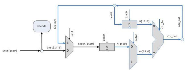
逻辑框图,蓝色为新增加的部分:
要做运算,先得有ALU,原书第3章讲了ALU的设计,这里照搬过来。
module alu(x, y, out, fn, zero);
input[15:0] x, y;
input[5:0] fn;
output[15:0] out;
output zero;
wire zx = fn[5];
wire nx = fn[4];
wire zy = fn[3];
wire ny = fn[2];
wire add = fn[1];
wire no = fn[0];
wire[15:0] x0 = zx ? 16'b0 : x;
wire[15:0] y0 = zy ? 16'b0 : y;
wire[15:0] x1 = nx ? ~x0 : x0;
wire[15:0] y1 = ny ? ~y0 : y0;
wire[15:0] out0 = add ? x1 + y1 : x1 & y1;
assign out = no ? ~out0 : out0;
assign zero = ~|out;
endmodule
然后是更新的Hack CPU设计,更新部分用蓝色标记。这一步主要是加了一个寄存器D,一个ALU,还有一些数据通路和控制信号。
module cpu(/* ... /*);
// 接口同“代码1”
reg[14:0] pc;
reg[15:0] a;
reg[15:0] d;
alu alu0(.x(d), .y(am), .out(alu_out), .fn(alu_fn), .zero(zero));
wire load_a = !inst[15] || inst[5];
wire load_d = inst[15] && inst[4];
wire sel_a = inst[15];
wire sel_am = inst[12];
wire zero;
wire[14:0] next_pc = pc + 15'b1;
wire[15:0] next_a = sel_a ? alu_out : {1'b0, inst[14:0]};
wire[15:0] next_d = alu_out;
wire[15:0] am = sel_am ? 16'bx : a;
wire[15:0] alu_out;
wire[5:0] alu_fn = inst[11:6];
assign inst_addr = pc;
always @(posedge clk)
if (!nrst) // 同步清零
pc <= 15'b0;
else
pc <= next_pc;
always @(posedge clk)
if (load_a)
a <= next_a;
always @(posedge clk)
if (load_d)
d <= next_d;
endmodule
2.3 完整的实现
剩下的工作是增加数据内存的访问功能,先定义Hack的RAM,这是一个同步的双口SRAM,可以用FPGA内置的存储单元实现。
module ram(clk, addr, rdata, wdata, we);
input clk, we;
input[7:0] addr;
output[15:0] rdata;
input[15:0] wdata;
reg[15:0] memory[0:255];
assign rdata = memory[addr];
always @(posedge clk)
if (we)
memory[addr] <= wdata;
endmodule
然后添加 RAM读写的data path,并支持跳转指令,这样得到了最终的设计,与书上的一摸一样。
module cpu(clk, nrst, inst_addr, inst, rdata, wdata, data_addr, we);
input clk, nrst;
input[15:0] inst;
input[15:0] rdata;
output[14:0] inst_addr, data_addr;
output[15:0] wdata;
output we;
reg[14:0] pc;
reg[15:0] a;
reg[15:0] d
alu alu0(.x(d), .y(am), .out(alu_out), .fn(alu_fn), .zero(zero));
wire load_a = !inst[15] || inst[5];
wire load_d = inst[15] && inst[4];
wire sel_a = inst[15];
wire sel_am = inst[12];
wire jump = (less_than_zero && inst[2])
|| (zero && inst[1])
|| (greater_than_zero && inst[0]);
wire sel_pc = inst[15] && jump;
wire zero;
wire less_than_zero = alu_out[15];
wire greater_than_zero = !(less_than_zero || zero);
wire[14:0] next_pc = sel_pc ? a[14:0] : pc + 15'b1;
wire[15:0] next_a = sel_a ? alu_out : {1'b0, inst[14:0]};
wire[15:0] next_d = alu_out;
wire[15:0] am = sel_am ? m : a;
wire[15:0] alu_out;
wire[5:0] alu_fn = inst[11:6];
wire[15:0] m = rdata;
assign inst_addr = pc;
assign data_addr = a[14:0];
assign wdata = alu_out;
assign we = inst[15] && inst[3];
always @(posedge clk)
if (!nrst)
pc <= 15'b0;
else
pc <= next_pc;
always @(posedge clk)
if (load_a)
a <= next_a;
always @(posedge clk)
if (load_d)
d <= next_d;
endmodule
描述整个Hack CPU只用了50行 Verilog代码。
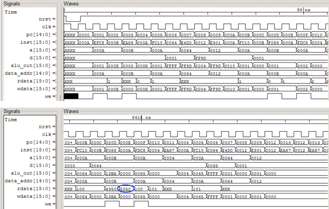
下面是书上第4章计算1+2+...+100的程序的仿真波形,计算结果5050出现在数据读端口:
3 不足与改进
Hack CPU尽管简单,却能够执行一般CPU的大部分功能,比如读写内存,算数与逻辑运算,条件判断与跳转。当然,也有一些明显的值得改进的地方。
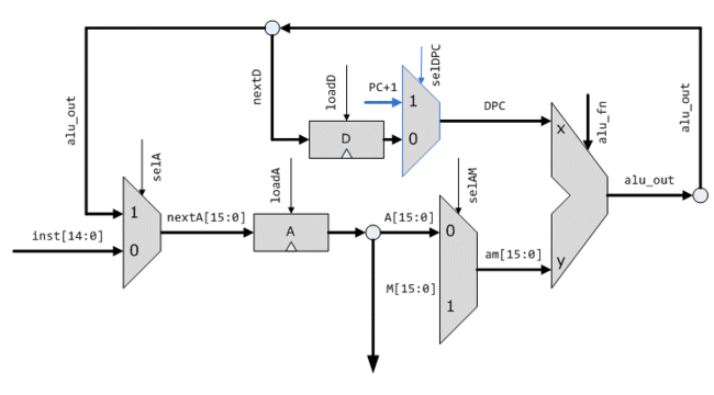
1. 不支持子程序调用,PC的值没法读出来并存到内存中。也就是说没法把返回地址存到函数调用栈中。这不难改进,只要在寄存器D之后放一个多路选择器,让PC+1的值也能参与运算。当然,需要扩充C指令的格式,把sel_dpc编码进去,可以用第13位。
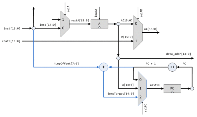
2. 不支持相对跳转,PC总是跳转到A所指的地址。不便于编写可重定位的代码。这个也不难解决,可以引入一种新的J指令(可以以二进制10开头,区别A指令和C指令),包含跳转条件和跳转偏移量,数据通路修改如下,只要增加一个加法器和选择通路。
3. 不支持中断,没法实现高效的IO。这个我还没有设计出一个好的解决方案。
4 附录A:Verilog工具与心得
l 免费的Verilog仿真器:Icarus Verilog [ http://www.icarus.com/eda/verilog/ ]
Windows版下载地址:http://bleyer.org/icarus/
我用的是iverilog-0.8.6_setup.exe
l 免费的波形查看器:GTKWave [ http://www.gpleda.org/tools/gtkwave/index.html ]
Windows版下载地址:http://www.dspia.com/gtkwave.html
我上一次用Verilog来做数字电路设计是在4年多以前(AES加密算法的FPGA实现,加密16字节用11个周期),今后用它的机会也很少,这里写一点心得,算是留个纪念吧。
用Verilog的首要原则是,心中先有电路,再用Verilog把它描述(describe)出来,毕竟Verilog是硬件描述语言(Hardware description language),不是程序设计语言。运用Verilog要掌握几种平衡:哪些需要人脑精心设计,哪些可以留给综合器(synthesizer)去优化;是把代码写得更通用(general),还是使用特定器件做优化(例如使用LPM或megafunction)。一般来说,数据通路(data path)是需要精心考虑的,而组合逻辑(比如CPU里的控制逻辑)尽可留给综合器。毕竟布尔函数的最小化算法已经很成熟了,比如Quine–McCluskey algorithm和Espresso heuristic logic minimizer。综合器在实现组合逻辑方面有很多花招可玩,比如AES加密算法里的Rijndael S-box是个256字节的纯粹的查找表,好的综合器会根据器件的资源自动选择ROM或组合逻辑来实现。设计时更多是在考虑寄存器(通常是D触发器)的安排、数据在每一拍如何流动。这和程序设计类似,优先设计数据结构,然后让算法自然地浮现出来。
另外,Verilog的重要用途是写test bench。通过看仿真波形来除错是低效的,对于hack这样的小型设计还行,对于稍微复杂一点的设计非得用test bench不可。数字设计基本上是测试驱动的。
5 附录B:另几个容易实现的CPU
5.1 Petzold’s
在《编码的奥秘》[http://www.china-pub.com/680] 第17章中,作者Charles Petzold由一个程序控制的累加器出发,逐步实现了一个简单的通用CPU。这也是我见到的最简单的CPU设计了。这一章可从china-pub付费下载。
5.2 Beta
MIT 6.004课程讲授的一个32-bit类MIPS指令集的CPU:http://tinyurl.com/2ppws
5.3 Magic-1
一个用TTL搭出来的能运行Minix 2.0.4的16位CPU:http://www.homebrewcpu.com/
