ims 核心网架构
The IP-Multimedia Subsystem (IMS) defines the functional architecture for a managed IP-based network. It aims to provide a means for carriers to create an open, standards-based network that delivers integrated multimedia services to increase revenue, while also reducing network CapEx and OpEx.
IMS was originally designed for third-generation mobile phones, but it has already been extended to handle access from WiFi networks, and is continuing to be extended into an access-independent platform for service delivery, including broadband fixed-line access. It promises to provide seamless roaming between mobile, public WiFi and private networks for a wide range of services and devices.
The IMS architecture has been designed to enable operators to provide a wide range of real-time, packet-based services and to track their use in a way that allows both traditional time-based charging as well as packet and service-based charging. It has become increasingly popular both with wireline and wireless service providers as it is designed to increase carrier revenues, deliver integrated multimedia services, and create an open, standards-based network.
IMS provides a wide range of session border control, including call access control, reachability and security. It also provides a framework for the deployment of both basic calling services and enhanced services, including
- multimedia messaging
- web integration
- presence-based services
- push-to-talk.
At the same time, it draws on the traditional telecommunications experience of
- guaranteed QoS
- flexible charging mechanisms (time-based, call-collect, premium rates)
- lawful intercept legislation compliance.
Network operators also hope that IMS will cut their CapEx and OpEx through the use of a converged IP backbone and the open IMS architecture.
- The IMS architecture defines many common components (for example, call control and configuration storage) so less development work is required to create a new service as this existing infrastructure can be reused.
- The use of standardized interfaces should increase competition between suppliers; preventing operators from being locked into a single supplier's proprietary interfaces.
As a result, IMS should enable new services to be rolled out more quickly and cheaply, compared with the traditional monolithic design of telephony services.
IMS Architecture
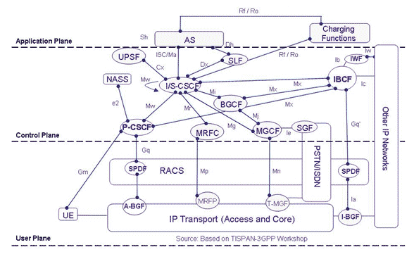
The diagram below shows the IP Multimedia Subsystem architecture.
IMS decomposes the networking infrastructure into separate functions with standardized interfaces between them. Each interface is specified as a "reference point", which defines both the protocol over the interface and the functions between which it operates. The standards do not mandate which functions should be co-located, as this depends on the scale of the application, and a single device may contain several functions.
The 3GPP architecture is split into three main planes or layers, each of which is described by a number of equivalent names: Service or Application Plane, Control or Signaling Plane, and User or Transport Plane.
Application Plane
The application plane provides an infrastructure for the provision and management of services, and defines standard interfaces to common functionality including
- configuration storage, identity management, user status (such as presence and location), which is held by the Home Subscriber Server (HSS)
- billing services, provided by a Charging Gateway Function (CGF)
- control of voice and video calls and messaging, provided by the control plane.
Control Plane
The control plane sits between the application and transport planes. It routes the call signaling, tells the transport plane what traffic to allow, and generates billing information for the use of the network.
At the core of this plane is the Call Session Control Function (CSCF), which comprises the following functions.
- The Proxy-CSCF (P-CSCF) is the first point of contact for users with the IMS. The P-CSCF is responsible for security of the messages between the network and the user and allocating resources for the media flows.
- The Interrogating-CSCF (I-CSCF) is the first point of contact from peered networks. The I-CSCF is responsible for querying the HSS to determine the S-CSCF for a user and may also hide the operator's topology from peer networks (Topology Hiding Inter-network Gateway, or THIG).
- The Serving-CSCF (S-CSCF) is the central brain. The S-CSCF is responsible for processing registrations to record the location of each user, user authentication, and call processing (including routing of calls to applications). The operation of the S-CSCF is controlled by policy stored in the HSS.
This distributed architecture provides an extremely flexible and scalable solution. For example, any of the CSCF functions can generate billing information for each operation.
The Control Plane also controls User Plane traffic through the Resource and Admission Control Subsystem (RACS). This consists of the Policy Decision Function (PDF), which implements local policy on resource usage, for example to prevent overload of particular access links, and Access-RAC Function (A-RACF), which controls QoS within the access network.
User Plane
The User plane provides a core QoS-enabled IPv6 network with access from User Equipment (UE) over mobile, WiFi and broadband networks. This infrastructure is designed to provide a wide range of IP multimedia server-based and P2P services.
Access into the core network is through Border Gateways (GGSN/PDG/BAS). These enforce policy provided by the IMS core, controlling traffic flows between the access and core networks.
Within the User Plane
- the Interconnect Border Control Function (I-BCF) controls transport level security and tells the RACS what resources are required for a call
- the I-BGF, A-BGF Border Gateway Functions provide media relay for hiding endpoint addresses with managed pinholes to prevent bandwidth theft, and implement NAPT and NAT/Firewall traversal for media flo
