配置MST实现负载均衡
配置MST实现负载均衡
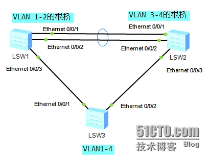
一、 实验拓扑:
(华为eNSP模拟器)

二、 实验环境要求:
1. VLAN规划如图;
2. SW1与SW2之间做链路捆绑;
3. 配置MST实现负载均衡
三、 配置文件及步骤:
1. SW1的配置
配置以太网通道
<Huawei>sy
[Huawei]sysname SW1
[SW1]vlan batch 1 to 4 //批量创建vlan 1到4
[SW1]int Eth-Trunk 1 //创建二层Eth-Trunk接口
[SW1-Eth-Trunk1]q
[SW1]int Ethernet 0/0/1
[SW1-Ethernet0/0/1]eth-trunk 1 //将接口加入eth-trunk 1
[SW1-Ethernet0/0/1]q
[SW1]int Ethernet 0/0/2
[SW1-Ethernet0/0/2]eth-trunk 1
[SW1]dis eth-trunk 1

[SW1]int Eth-Trunk 1
[SW1-Eth-Trunk1]port link-type trunk //将Eth-Trunk 1 设为trunk类型
[SW1-Eth-Trunk1]port trunk allow-pass vlan all //允许所有VLAN流量通过
[SW1-Eth-Trunk1]int e0/0/3
[SW1-Ethernet0/0/3]port link-type trunk
[SW1-Ethernet0/0/3]port trunk allow-pass vlan all
<SW1>dis vlan

配置mstp
[SW1]stp mode mstp //设置交换机的工作模式为mstp
[SW1]stp region-configuration //进入MST域配置没事
[SW1-mst-region]region-name test //配置MST域的域名为test
[SW1-mst-region]instance 1 vlan 1 to 2 //配置多生成树实例和VLAN的映射关系,实例1对应VLAN1到2
[SW1-mst-region]instance 2 vlan 3 to 4
[SW1-mst-region]active region-configuration //激活MST域的配置
[SW1-mst-region]q
[SW1]stp instance 1 root primary //配置SW1是实例1的根桥
[SW1]stp instance 2 root secondary //配置SW1是实例2的备份根桥
或者[SW1]stp instance 1 priority0
[SW2]stp instance 2 priority 0
或者[SW1]stp instance 2 priority4096
[SW2]stpinstance 1 priority 4096
[SW1]stp enable //启用交换机的mstp功能
[SW1]int Eth-Trunk 1
[SW1-Eth-Trunk1]stp enable //启用交换机端口的mstp功能
[SW1-Eth-Trunk1]stp root-protection //启用根保护
[SW1-Eth-Trunk1]int e0/0/3
[SW1-Ethernet0/0/3]stp enable
[SW1-Ethernet0/0/3]stp root-protecti
2. SW2的配置
配置以太网通道
<Huawei>sy
[Huawei]sysname SW2
[SW2]int Eth-Trunk 1
[SW2-Eth-Trunk1]q
[SW2]int Ethernet 0/0/1
[SW2-Ethernet0/0/1]eth-trunk 1
[SW2]int Ethernet 0/0/2
[SW2-Ethernet0/0/2]eth-trunk 1
[SW2]dis eth-trunk 1

[SW2]vlan batch 1 to 4
[SW2]int Eth-Trunk 1
[SW2-Eth-Trunk1]port link-type trunk
[SW2-Eth-Trunk1]port trunk allow-pass vlan all
[SW2-Eth-Trunk1]int e0/0/3
[SW2-Ethernet0/0/3]port link-type trunk
[SW2-Ethernet0/0/3]port trunk allow-pass vlan all
<SW2>dis vlan

配置mstp
[SW2]stpmode mstp
[SW2]stp region-configuration
[SW2-mst-region]region-nametest
[SW2-mst-region]instance 1vlan 1 to 2
[SW2-mst-region]instance 2vlan 3 to 4
[SW2-mst-region]activeregion-configuration
[SW2-mst-region]q
[SW2]stp instance 2 rootprimary
[SW2]stp instance 1 rootsecondary
[SW2]stp enable
[SW2]int Eth-Trunk 1
[SW2-Eth-Trunk1]stp enable
[SW2-Eth-Trunk1]stp root-protection
[SW2-Eth-Trunk1]int e0/0/3
[SW2-Ethernet0/0/3]stp enable
[SW2-Ethernet0/0/3]stproot-protection
3. SW3的配置
配置以太网通道
<Huawei>sy
[Huawei]sysname SW3
[SW3]vlan batch 1 to 4
[SW3]int e0/0/1
[SW3-Ethernet0/0/1]port link-type trunk
[SW3-Ethernet0/0/1]port trunk allow-pass vlan all
[SW3-Ethernet0/0/1]int e0/0/2
[SW3-Ethernet0/0/2]port link-type trunk
[SW3-Ethernet0/0/2]port trunk allow-pass vlan all
<SW3>dis vlan

配置mstp
[SW3]stp mode mstp
[SW3]stp region-configuration
[SW3-mst-region]region-name test
[SW3-mst-region]instance 1 vlan 1 to 2
[SW3-mst-region]instance 2 vlan 3 to 4
[SW3-mst-region]active region-configuration
[SW3]stp enable
[SW3]int e0/0/1
[SW3-Ethernet0/0/1]stp enable
[SW3-Ethernet0/0/1]int e0/0/2
[SW3-Ethernet0/0/2]stp enable
四、 结果验证 :
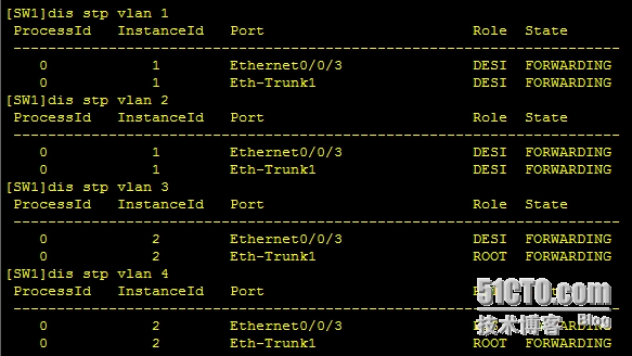
[SW1]dis stp brief //查看端口状态和端口的保护类型


通过上面的图可以得出:SW1为实例1即VLAN1和2的根桥,Eth-Trunk1和Ethernet0/0/3都是指定端口;在实例2即VLAN3和4中为非根桥,Eth-Trunk1为根端口,Ethernet0/0/3为指定端口。
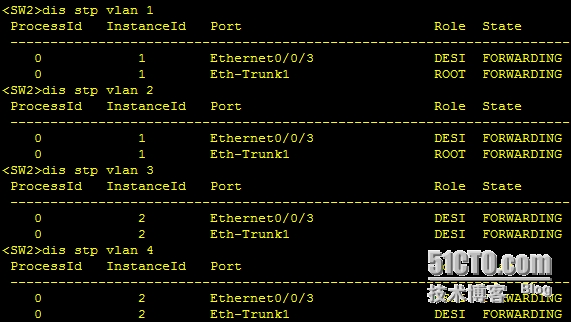
[SW2]dis stp brief


通过上面的图可以得出:SW2为实例2的根桥,Eth-Trunk1和Ethernet0/0/3都是指定端口;在实例1中为非根桥,Eth-Trunk1为根端口,Ethernet0/0/3为指定端口。
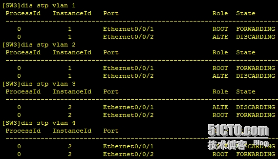
[SW3]dis stp brief


通过上面的图可以得出:SW3既不是实例1的根桥也不是实例2 的根桥,在实例1 中Ethernet0/0/1 为根端口,Ethernet0/0/2为阻塞端口;在实例2中Ethernet0/0/2 为根端口,Ethernet0/0/1为阻塞端口
结论:
RSTP和MSTP
RSTP:局域网内所有的VLAN共享一棵生成树,因此无法在VLAN间实现数据流量的负载均衡,链路被阻塞后将不承载任何流量,造成带宽浪费,还有可能造成部分VLAN的报文无法转发
MSTP:可以为每个VLAN生成一个生成树,不同的VLAN通过不同的生成树转发流量,每棵生成树之间相互独立,互不影响,可在VLAN间实现负载均衡