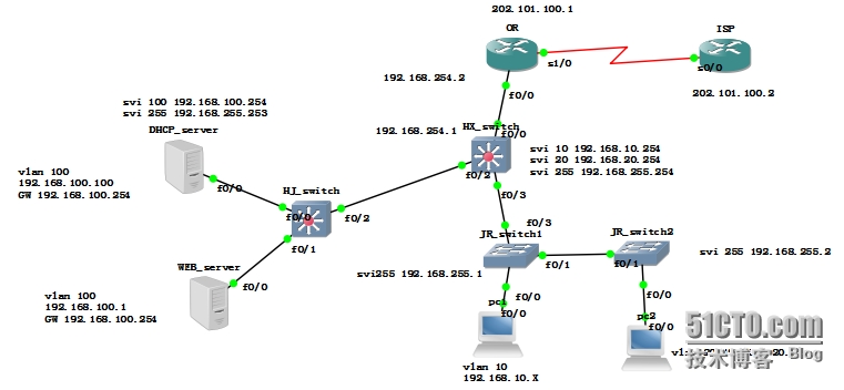
小型交换综合实验

实验要求:PC1和PC2通过DHCP服务器获取地址
PC机和服务器能够连接到外网
PC机可以远程管理交换机
首先配置DHCP服务器:(拓扑中交换机 pc 服务器均用思科3640路由器模拟)n
conf t
server dhcp
ip dhcp pool vlan10
network 192.168.10.0 /24
default-router 192.168.10.254 (给动态地址分配网关)
ip dhcp pool vlan20
network 192.168.20.0 /24
defaut-router 192.168.20.254
ip dhcp excluded-address 192.168.10.254 (给PC分配地址时 排除网关地址)
ip dhcp excluded-add 192.168.20.254
int f0/0
ip add 192.168.100.100 255.255.255.0
no sh
PC1:
conf t
no ip routing
int f0/0
ip add dhcp (PC2同此操作)
JR_switch1:
vlan database
vlan 10
vlan 20
vlan 255 (管理vlan)
int vlan 255
ip add 192.168.255.1 255.255.255.0
no sh
ip default-gataway 192.168.255.254
int f0/0
switchport mode access
sw access vlan 10
int f0/1
sw mode trunk
int f0/3
sw mode trunk
JR_switch2 (类似操作)
HX_switch(三层交换机):
int f0/3
sw mo trunk
int f0/2
sw mo trunk
vlan database
vlan 10
vlan 20
vlan 255
int vlan 10
ip add 192.168.10.254 255.255.255.0
ip help-address 192.168.100.100 (DHCP中继)
no sh
int vlan 20
ip add 192.168.20.254 255.255.255.0
ip help-address 192.168.100.100
int vlan 255
ip add 192.168.255.254 255.255.255.0
no sh
int f0/0
no switchport (由于是模拟器模拟的三层交换机 用此命令开启三层端口 真机不需此命令)
ip add 192.168.254.1 255.255.255.0
no sh
ip route 0.0.0.0 0.0.0.0 192.168.254.2
ip route 192.168.100.0 255.255.255.0 192.168.255.253(SVI接口地址)
HJ_switch:
vlan database
vlan 100
vlan 255
int vlan 100
ip add 192.168.100.254 255.255.255.0
no sh
int vlan 255
ip add 192.168.255.253 255.255.255.0
no sh
int f0/0
sw mo access
sw access vlan 100
int f0/3
sw mode trunk
ip route 0.0.0.0 0.0.0.0 192.168.255.254 (一般汇聚层交换机都处于边界 所以配置了默认路由)
边界路由器OR:
int f0/0
ip add 192.168.254.2 255.255.255.0
ip nat inside
no sh
int s1/0
ip add 202.101.100.1 255.255.255.0
ip nat outside
no sh
acce-list 1 permit any
ip nat pool ccnp 202.101.100.1 202.101.100.1 netmask 255.255.255.0
ip nat inside source list 1 pool ccnp overload (PAT的配置)
ip route 192.168.0.0 255.255.0.0 192.168.254.1 (配置路由到达内网)
ip route 0.0.0.0 0.0.0.0 202.101.100.2 (配置默认路由去外网)
ISP路由器:
int s0/0
ip add 202.101.100.2 255.255.255.0
no sh
int lo0
ip add 3.3.3.3 255.255.255.0 (测试用)
no sh
基本配置已经完成了 现在进行DHCP测试,之前我们PC机是没有配置IP的 现在 sh ip int bri 查看


PC获取地址后 对服务器、外网以及交换机的telnet测试如下:


这个实验看起来比较简单,其实里面有很多小细节要注意,比如说JR_switch1为什么要配置vlan20?三层交换机之间的路由以及DHCP的中继等细节需注意。上面这个拓扑以及简化了,其实现实环境中上图就是一个典型的小型园区网,还必须得进行冗余和负载均衡的配置以及channel端口的启用,以达到稳定网络提高传输速率。
本文出自 “rookie cisco” 博客,谢绝转载!