自己动手做一个机器人——支持无线和蓝牙
[youku id="XNjQ2NTQ1MzQ4"]
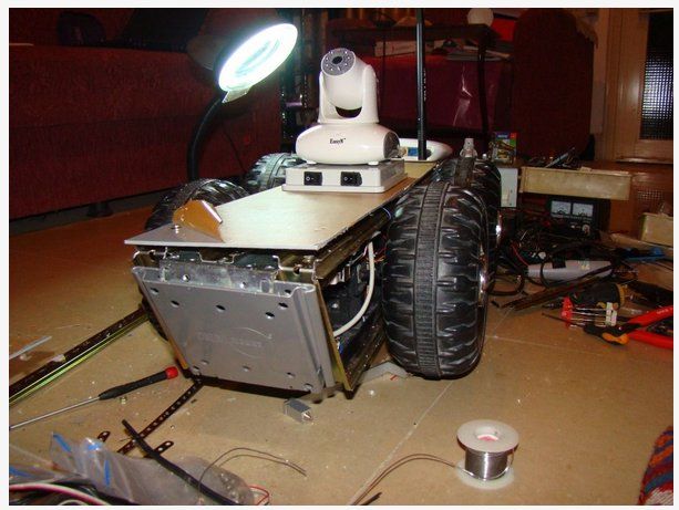
第1步: 车体结构
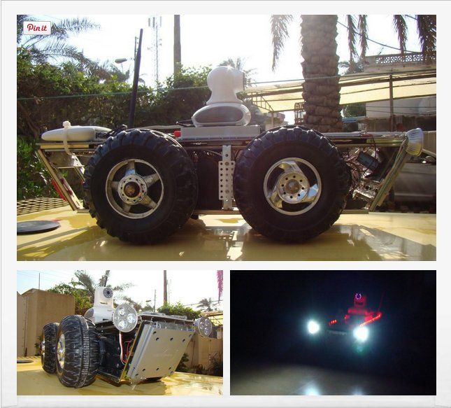
我从废品回收站找到了两辆坏掉的儿童玩具车,拆下了电机,变速箱,和轮胎。这些花费了我大概十块钱,我用钢轨和塑料板将框架做好,如图示。


 第2步:连接图
电路部分的关键是使用ATMEGA16单片机的串行口,电路由以下元件组成:
- 由两个L298组成的H桥驱动
- Atmega16 单片机
- ULN2003作为LED驱动
- 串行蓝牙模块
- 以太网-串口转换器
- WiFi接入点
- Easy N网络摄像头
- 12V的电源使用7805和7809为网络摄像头和路由供电
- 6V电机电源
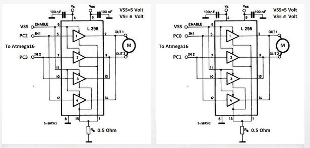
第3步:H桥电路
两个L298制成的双H桥驱动的连接示意如图,电机在6V,2.4A下运行,L298的最大允许电流请查阅数据手册。
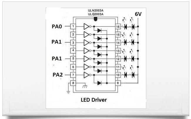
第4步:LED驱动
ULN2003达林顿管阵列是一个较简单的驱动LED的方案,它提供了7个输出,电路如图。数据手册如下。
第5步:单片机电路
源代码的调试平台是ATMEL AVR studio 4使用AVR MKII ISP下载器。写代码需要:
- 使能Atmega16单片机的串行输入输出
- 从PC机或平板上发送ASCII码
- 将接收到的ASCII码转换成特定的信息输出到端口A和端口C
如图所示,16Mhz外部频率谐振器的熔断位需要设置成:高位0xc9,低位0xff。
代码如下:
/*
ATmega16 16MHz external frequency resonator
Baud Rate 9600 No Parity,1 Stop Bit,Flow Control:None
*/

#include <avr/io.h>
#include <inttypes.h>
#include <util/delay.h>

void USARTInit(uint16_t ubrr_value)
{

    //Set Baud rate
    UBRRL = ubrr_value;
    UBRRH = (ubrr_value>>8);

    UCSRC=(1<<URSEL)|(3<<UCSZ0); // Set Asynchronous mode,No Parity ,1 StopBit
    UCSRB=(1<<RXEN)|(1<<TXEN); //Enable The receiver and transmitter
}

char USARTReadChar()
{
    while(!(UCSRA & (1<<RXC))) {
        // do nothing
    }
    return UDR;
}

void USARTWriteChar(char data)
{
    while(!(UCSRA & (1<<UDRE))) {
        //do nothing
    }
    UDR=data;
}

void main()
{
    DDRC=0xff;
    DDRA=0xff;
    char data;
    USARTInit(103); //for 16Mhz and baud 9600 UBRR = 103 and for baud 19200 UBRR = 51

    while(1) {
        data=USARTReadChar();
        if (data==0x71) {
            PORTC=0b10000000;
            USARTWriteChar('Q');
        } //q in ascii

        if (data==0x77) {
            PORTC=0b00001001;
            USARTWriteChar('w');
        } //w in ascii Forward

        if (data==0x65) {
            PORTC=0b01000000;
            USARTWriteChar('e');
        } //e in ascii

        if (data==0x61) {
            PORTC=0b00000011;
            USARTWriteChar('A');
        } //a in ascii Left

        if (data==0x73) {
            PORTC=0b00000000;
            USARTWriteChar('s');
        } //s in ascii Stop

        if (data==0x64) {
            PORTC=0b00001100;
            USARTWriteChar('d');
        } //d in ascii Right

        if (data==0x7A) {
            PORTC=0b00100000;
            USARTWriteChar('z');
        } //z in ascii

        if (data==0x78) {
            PORTC=0b10000110;
            USARTWriteChar('x');
        } //x in ascii Backward

        if (data==0x99) {
            PORTC=0b11110000;
            USARTWriteChar('c');
        } //c in ascii

        if (data==0x69) {
            PORTC=0b00001001;
            _delay_ms(200);
            PORTC=0b00000000;
        } //i in ascii Forward

        if (data==0x6A) {
            PORTC=0b00000011;
            _delay_ms(200);
            PORTC=0b00000000;
        } //j in ascii Left

        if (data==0x6C) {
            PORTC=0b00001100;
            _delay_ms(200);
            PORTC=0b00000000;
        } //l in ascii Right

        if (data==0x6B) {
            PORTC=0b00000110;
            _delay_ms(200);
            PORTC=0b00000000;
        } //k in ascii Back

        if (data==0x31) {
            PORTA=0b00000001;
            USARTWriteChar('1');
        } //1 in ascii //2 LED On

        if (data==0x32) {
            PORTA=0b00000010;
            USARTWriteChar('2');
        } //2 in ascii //4 LED on

        if (data==0x33) {
            PORTA=0b00000111;
            USARTWriteChar('3');
        } //3 in ascii //6 LED on

        if (data==0x34) {
            PORTA=0b00001000;
            USARTWriteChar('4');
        } //4 in ascii //Red LED on

        if (data==0x35) {
            PORTA=0b00010000;
            USARTWriteChar('5');
        } //5 in ascii

        if (data==0x36) {
            PORTA=0b00100000;
            USARTWriteChar('6');
        } //6 in ascii

        if (data==0x37) {
            PORTA=0b01000000;
            USARTWriteChar('7');
        } //7 in ascii

        if (data==0x38) {
            PORTA=0b10000000;
            USARTWriteChar('8');
        } //8 in ascii

        if (data==0x39) {
            PORTA=0b00000000;
            USARTWriteChar('9');
        } //9 in ascii //All Off
        else { }
    }
}
第6步:以太网-串口转换器
我从以下网址得到了转换模块。
接线方法:
- VDD接5V电源
- GND接地
- RX接Atmega16的TX
- TX接Atmega16的RX
- CFG 接到逻辑正的时候是普通模式,接到逻辑负的时候是配置模式
要配置这个模块RS232-TTL电平转换模块也是有必要的。你可以从以上网址下载到所有文档。
在这个项目中,我将转换器配置如下:
- 工作模式:TCP/IP链接
- 模块IP :192.168.1.2
- 子网掩码:255.255.255.0
- 默认网关:192.168.1.1(接入点IP)
- 奇偶校验位/数据位/停止位:无/8/1
- 目的IP :192.168.1.3(平板的IP地址)
- 目的端口:8234
- 波特率 :9600
第7步:Com-Redirector软件
 这个软件用来在你的平板上建立虚拟摄像头,因为并没有东西直接连在您的平板上(相当于一个驱动)。要想通过这个虚拟串口发送信息可以使用Putty或者hyper等终端软件。更多信息可以观看以下视频。
[youku id="XNjQ2NTQ2MzYw"]
第8步:串口蓝牙模块
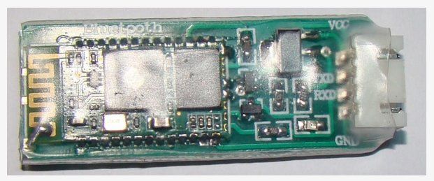
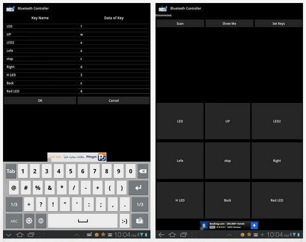 我从以下的网址得到了这个从模式下的串口蓝牙模块(包括所有的相关文档)Pass Key为:1234
你可以在Android market上面下载到支持这个模块的蓝牙控制器软件,使用起来非常简单。
[youku id="XNjQ2NTQ4MDUy"]
第9步:转换开关
 最后,我连接了一个转换开关用来选择无线连接的模式(WiFi或是蓝牙)
原文链接: Husham Samir 翻译: 极客范 - Dimpagger
译文链接: http://www.geekfan.net/4385/
[ 转载请保留原文出处、译者和译文链接。]
