USB设备开发---- USB固件开发
上篇介绍了基于libusb的无驱动设计,上位机没问题了,现在还留下个下位机的问题,该项目中USB下位机采用的Cypress的CY7C68013A控制芯片, 下面来仔细看如何编写下位机的固件程序(firmware)。
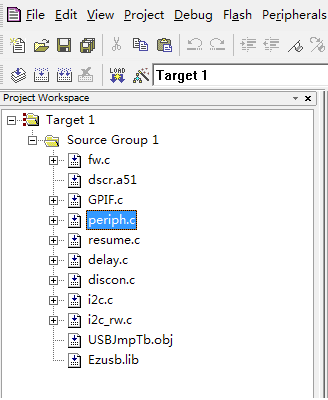
先看看工程的结构,如下图所示(开发工具为Keil uVision3):
其中:
(1): fw.c: 这个文件是整个USB的固件的根本,USB协议方面的通信都是在这里完成的,包括上电枚举,重枚举,唤醒以及调用用户自己的程序和控制命令等等。 一般的开发,该文件无需修改。固件的main程序就位于该文件中,概括来说,它首先进行一系列通用初始化设置,并调用void TD_Init(void)函数来实现用户的特殊初始化设置。之后,程序会一直监视是否有指令收到,并在空闲的时候反复调用TD_Poll()函数来实现我们用户的功能。代码如下:
				//-----------------------------------------------------------------------------
// File:      fw.c
// Contents:  Firmware frameworks task dispatcher and device request parser
//            source.
//
// indent 3.  NO TABS!
//
// $Revision: 18 $
// $Date: 12/04/01 5:33p $
//
//   Copyright (c) 1997 AnchorChips, Inc. All rights reserved
//

//-----------------------------------------------------------------------------
#include ".\Inc\fx2.h"
#include ".\Inc\fx2regs.h"

//-----------------------------------------------------------------------------
// Constants
//-----------------------------------------------------------------------------
#define DELAY_COUNT   0x9248*8L  // Delay for 8 sec at 24Mhz, 4 sec at 48
#define _IFREQ  48000            // IFCLK constant for Synchronization Delay
#define _CFREQ  48000            // CLKOUT constant for Synchronization Delay

//-----------------------------------------------------------------------------
// Random Macros
//-----------------------------------------------------------------------------
#define   min(a,b) (((a)<(b))?(a):(b))
#define   max(a,b) (((a)>(b))?(a):(b))

  // Registers which require a synchronization delay, see section 15.14
  // FIFORESET        FIFOPINPOLAR
  // INPKTEND         OUTPKTEND
  // EPxBCH:L         REVCTL
  // GPIFTCB3         GPIFTCB2
  // GPIFTCB1         GPIFTCB0
  // EPxFIFOPFH:L     EPxAUTOINLENH:L
  // EPxFIFOCFG       EPxGPIFFLGSEL
  // PINFLAGSxx       EPxFIFOIRQ
  // EPxFIFOIE        GPIFIRQ
  // GPIFIE           GPIFADRH:L
  // UDMACRCH:L       EPxGPIFTRIG
  // GPIFTRIG

  // Note: The pre-REVE EPxGPIFTCH/L register are affected, as well...
  //      ...these have been replaced by GPIFTC[B3:B0] registers

#include ".\Inc\fx2sdly.h"             // Define _IFREQ and _CFREQ above this #include

//-----------------------------------------------------------------------------
// Global Variables
//-----------------------------------------------------------------------------
volatile BOOL   GotSUD;
BOOL      Rwuen;
BOOL      Selfpwr;
volatile BOOL   Sleep;                  // Sleep mode enable flag

WORD   pDeviceDscr;   // Pointer to Device Descriptor; Descriptors may be moved
WORD   pDeviceQualDscr;
WORD   pHighSpeedConfigDscr;
WORD   pFullSpeedConfigDscr;
WORD   pConfigDscr;
WORD   pOtherConfigDscr;
WORD   pStringDscr;

//-----------------------------------------------------------------------------
// Prototypes
//-----------------------------------------------------------------------------
void SetupCommand(void);
void TD_Init(void);
void TD_Poll(void);
BOOL TD_Suspend(void);
BOOL TD_Resume(void);

BOOL DR_GetDescriptor(void);
BOOL DR_SetConfiguration(void);
BOOL DR_GetConfiguration(void);
BOOL DR_SetInterface(void);
BOOL DR_GetInterface(void);
BOOL DR_GetStatus(void);
BOOL DR_ClearFeature(void);
BOOL DR_SetFeature(void);
BOOL DR_VendorCmnd(void);

// this table is used by the epcs macro
const char code  EPCS_Offset_Lookup_Table[] =
{
   0,    // EP1OUT
   1,    // EP1IN
   2,    // EP2OUT
   2,    // EP2IN
   3,    // EP4OUT
   3,    // EP4IN
   4,    // EP6OUT
   4,    // EP6IN
   5,    // EP8OUT
   5,    // EP8IN
};

// macro for generating the address of an endpoint's control and status register (EPnCS)
#define epcs(EP) (EPCS_Offset_Lookup_Table[(EP & 0x7E) | (EP > 128)] + 0xE6A1)

//-----------------------------------------------------------------------------
// Code
//-----------------------------------------------------------------------------

// Task dispatcher
void main(void)
{
   DWORD   i;
   WORD   offset;
   DWORD   DevDescrLen;
   DWORD   j=0;
   WORD   IntDescrAddr;
   WORD   ExtDescrAddr;

   // Initialize Global States
   Sleep = FALSE;               // Disable sleep mode
   Rwuen = FALSE;               // Disable remote wakeup
   Selfpwr = FALSE;            // Disable self powered
   GotSUD = FALSE;               // Clear "Got setup data" flag

   // Initialize user device
   TD_Init();

   // The following section of code is used to relocate the descriptor table.
   // Since the SUDPTRH and SUDPTRL are assigned the address of the descriptor
   // table, the descriptor table must be located in on-part memory.
   // The 4K demo tools locate all code sections in external memory.
   // The descriptor table is relocated by the frameworks ONLY if it is found
   // to be located in external memory.
   pDeviceDscr = (WORD)&DeviceDscr;
   pDeviceQualDscr = (WORD)&DeviceQualDscr;
   pHighSpeedConfigDscr = (WORD)&HighSpeedConfigDscr;
   pFullSpeedConfigDscr = (WORD)&FullSpeedConfigDscr;
   pStringDscr = (WORD)&StringDscr;

   if ((WORD)&DeviceDscr & 0xe000)
   {
      IntDescrAddr = INTERNAL_DSCR_ADDR;
      ExtDescrAddr = (WORD)&DeviceDscr;
      DevDescrLen = (WORD)&UserDscr - (WORD)&DeviceDscr + 2;
      for (i = 0; i < DevDescrLen; i++)
         *((BYTE xdata *)IntDescrAddr+i) = 0xCD;
      for (i = 0; i < DevDescrLen; i++)
         *((BYTE xdata *)IntDescrAddr+i) = *((BYTE xdata *)ExtDescrAddr+i);
      pDeviceDscr = IntDescrAddr;
      offset = (WORD)&DeviceDscr - INTERNAL_DSCR_ADDR;
      pDeviceQualDscr -= offset;
      pConfigDscr -= offset;
      pOtherConfigDscr -= offset;
      pHighSpeedConfigDscr -= offset;
      pFullSpeedConfigDscr -= offset;
      pStringDscr -= offset;
   }

   EZUSB_IRQ_ENABLE();            // Enable USB interrupt (INT2)
   EZUSB_ENABLE_RSMIRQ();            // Wake-up interrupt

   INTSETUP |= (bmAV2EN | bmAV4EN);     // Enable INT 2 & 4 autovectoring

   USBIE |= bmSUDAV | bmSUTOK | bmSUSP | bmURES | bmHSGRANT;   // Enable selected interrupts
   EA = 1;                  // Enable 8051 interrupts

#ifndef NO_RENUM
   // Renumerate if necessary.  Do this by checking the renum bit.  If it
   // is already set, there is no need to renumerate.  The renum bit will
   // already be set if this firmware was loaded from an eeprom.
   if(!(USBCS & bmRENUM))
   {
       EZUSB_Discon(TRUE);   // renumerate
   }
#endif

   // unconditionally re-connect.  If we loaded from eeprom we are
   // disconnected and need to connect.  If we just renumerated this
   // is not necessary but doesn't hurt anything
   USBCS &=~bmDISCON;

   CKCON = (CKCON&(~bmSTRETCH)) | FW_STRETCH_VALUE; // Set stretch to 0 (after renumeration)

   // clear the Sleep flag.
   Sleep = FALSE;

   // Task Dispatcher
   while(TRUE)               // Main Loop
   {
      if(GotSUD)            // Wait for SUDAV
      {
         SetupCommand();          // Implement setup command
         GotSUD = FALSE;          // Clear SUDAV flag
      }

      // Poll User Device
      // NOTE: Idle mode stops the processor clock.  There are only two
      // ways out of idle mode, the WAKEUP pin, and detection of the USB
      // resume state on the USB bus.  The timers will stop and the
      // processor will not wake up on any other interrupts.
      if (Sleep)
          {
          if(TD_Suspend())
              {
              Sleep = FALSE;            // Clear the "go to sleep" flag.  Do it here to prevent any race condition between wakeup and the next sleep.
              do
                  {
                    EZUSB_Susp();         // Place processor in idle mode.
                  }
                while(!Rwuen && EZUSB_EXTWAKEUP());
                // Must continue to go back into suspend if the host has disabled remote wakeup
                // *and* the wakeup was caused by the external wakeup pin.

             // 8051 activity will resume here due to USB bus or Wakeup# pin activity.
             EZUSB_Resume();   // If source is the Wakeup# pin, signal the host to Resume.
             TD_Resume();
             }
          }
      TD_Poll();
   }
}

// Device request parser
void SetupCommand(void)
{
   void   *dscr_ptr;

   switch(SETUPDAT[1])
   {
      case SC_GET_DESCRIPTOR:                  // *** Get Descriptor
         if(DR_GetDescriptor())
            switch(SETUPDAT[3])
            {
               case GD_DEVICE:            // Device
                  SUDPTRH = MSB(pDeviceDscr);
                  SUDPTRL = LSB(pDeviceDscr);
                  break;
               case GD_DEVICE_QUALIFIER:            // Device Qualifier
                  SUDPTRH = MSB(pDeviceQualDscr);
                  SUDPTRL = LSB(pDeviceQualDscr);
                  break;
               case GD_CONFIGURATION:         // Configuration
                  SUDPTRH = MSB(pConfigDscr);
                  SUDPTRL = LSB(pConfigDscr);
                  break;
               case GD_OTHER_SPEED_CONFIGURATION:  // Other Speed Configuration
                  SUDPTRH = MSB(pOtherConfigDscr);
                  SUDPTRL = LSB(pOtherConfigDscr);
                  break;
               case GD_STRING:            // String
                  if(dscr_ptr = (void *)EZUSB_GetStringDscr(SETUPDAT[2]))
                  {
                     SUDPTRH = MSB(dscr_ptr);
                     SUDPTRL = LSB(dscr_ptr);
                  }
                  else
                     EZUSB_STALL_EP0();   // Stall End Point 0
                  break;
               default:            // Invalid request
                  EZUSB_STALL_EP0();      // Stall End Point 0
            }
         break;
      case SC_GET_INTERFACE:                  // *** Get Interface
         DR_GetInterface();
         break;
      case SC_SET_INTERFACE:                  // *** Set Interface
         DR_SetInterface();
         break;
      case SC_SET_CONFIGURATION:               // *** Set Configuration
         DR_SetConfiguration();
         break;
      case SC_GET_CONFIGURATION:               // *** Get Configuration
         DR_GetConfiguration();
         break;
      case SC_GET_STATUS:                  // *** Get Status
         if(DR_GetStatus())
            switch(SETUPDAT[0])
            {
               case GS_DEVICE:            // Device
                  EP0BUF[0] = ((BYTE)Rwuen << 1) | (BYTE)Selfpwr;
                  EP0BUF[1] = 0;
                  EP0BCH = 0;
                  EP0BCL = 2;
                  break;
               case GS_INTERFACE:         // Interface
                  EP0BUF[0] = 0;
                  EP0BUF[1] = 0;
                  EP0BCH = 0;
                  EP0BCL = 2;
                  break;
               case GS_ENDPOINT:         // End Point
                  EP0BUF[0] = *(BYTE xdata *) epcs(SETUPDAT[4]) & bmEPSTALL;
                  EP0BUF[1] = 0;
                  EP0BCH = 0;
                  EP0BCL = 2;
                  break;
               default:            // Invalid Command
                  EZUSB_STALL_EP0();      // Stall End Point 0
            }
         break;
      case SC_CLEAR_FEATURE:                  // *** Clear Feature
         if(DR_ClearFeature())
            switch(SETUPDAT[0])
            {
               case FT_DEVICE:            // Device
                  if(SETUPDAT[2] == 1)
                     Rwuen = FALSE;       // Disable Remote Wakeup
                  else
                     EZUSB_STALL_EP0();   // Stall End Point 0
                  break;
               case FT_ENDPOINT:         // End Point
                  if(SETUPDAT[2] == 0)
                  {
                     *(BYTE xdata *) epcs(SETUPDAT[4]) &= ~bmEPSTALL;
                     EZUSB_RESET_DATA_TOGGLE( SETUPDAT[4] );
                  }
                  else
                     EZUSB_STALL_EP0();   // Stall End Point 0
                  break;
            }
         break;
      case SC_SET_FEATURE:                  // *** Set Feature
         if(DR_SetFeature())
            switch(SETUPDAT[0])
            {
               case FT_DEVICE:            // Device
                  if(SETUPDAT[2] == 1)
                     Rwuen = TRUE;      // Enable Remote Wakeup
                  else if(SETUPDAT[2] == 2)
                     // Set Feature Test Mode.  The core handles this request.  However, it is
                     // necessary for the firmware to complete the handshake phase of the
                     // control transfer before the chip will enter test mode.  It is also
                     // necessary for FX2 to be physically disconnected (D+ and D-)
                     // from the host before it will enter test mode.
                     break;
                  else
                     EZUSB_STALL_EP0();   // Stall End Point 0
                  break;
               case FT_ENDPOINT:         // End Point
                  *(BYTE xdata *) epcs(SETUPDAT[4]) |= bmEPSTALL;
                  break;
            }
         break;
      default:                     // *** Invalid Command
         if(DR_VendorCmnd())
            EZUSB_STALL_EP0();            // Stall End Point 0
   }

   // Acknowledge handshake phase of device request
   EP0CS |= bmHSNAK;
}

// Wake-up interrupt handlear
void resume_isr(void) interrupt WKUP_VECT
{
   EZUSB_CLEAR_RSMIRQ();
}
(2):dscr.a51: 这个文件是USB描述符文件,包括了设备描述符,接口描述符,端点描述符,字符串等等。如要修改从PC端看到的该USB设备的名字,可通过修改该文件中的字符串内容来实现。
(3):GPIF.c:本项目中用到了GPIF功能(Cypress定义的一种接口),(安装gpif designer软件,根据自己需要完成相应时序图,即可自动生成GPIF.c文件)。
// GPIF Program Code

// DO NOT EDIT ...
#include "fx2.h"
#include "fx2regs.h"
#include "fx2sdly.h"     // SYNCDELAY macro
// END DO NOT EDIT

// DO NOT EDIT ...
const char xdata WaveData[128] =
{
// Wave 0
/* LenBr */ 0x01,     0x01,     0x9A,     0x01,     0x01,     0x01,     0x01,     0x07,
/* Opcode*/ 0x00,     0x00,     0x01,     0x02,     0x02,     0x02,     0x02,     0x02,
/* Output*/ 0x03,     0x01,     0x01,     0x01,     0x01,     0x01,     0x01,     0x07,
/* LFun  */ 0x00,     0x00,     0x00,     0x00,     0x00,     0x00,     0x00,     0x3F,
// Wave 1
/* LenBr */ 0x01,     0x02,     0x01,     0x01,     0x01,     0x01,     0x01,     0x07,
/* Opcode*/ 0x02,     0x02,     0x02,     0x02,     0x02,     0x02,     0x02,     0x02,
/* Output*/ 0x02,     0x00,     0x00,     0x00,     0x00,     0x00,     0x00,     0x07,
/* LFun  */ 0x00,     0x00,     0x00,     0x00,     0x00,     0x00,     0x00,     0x3F,
// Wave 2
/* LenBr */ 0x01,     0x01,     0x01,     0x01,     0x01,     0x01,     0x01,     0x07,
/* Opcode*/ 0x02,     0x02,     0x02,     0x02,     0x02,     0x02,     0x02,     0x02,
/* Output*/ 0x07,     0x07,     0x07,     0x07,     0x07,     0x07,     0x07,     0x07,
/* LFun  */ 0x00,     0x00,     0x00,     0x00,     0x00,     0x00,     0x00,     0x3F,
// Wave 3
/* LenBr */ 0x01,     0x01,     0x01,     0x01,     0x01,     0x01,     0x01,     0x07,
/* Opcode*/ 0x02,     0x02,     0x02,     0x02,     0x02,     0x02,     0x02,     0x02,
/* Output*/ 0x07,     0x07,     0x07,     0x07,     0x07,     0x07,     0x07,     0x07,
/* LFun  */ 0x00,     0x00,     0x00,     0x00,     0x00,     0x00,     0x00,     0x3F,
};
// END DO NOT EDIT

// DO NOT EDIT ...
const char xdata FlowStates[36] =
{
/* Wave 0 FlowStates */ 0x00,0x00,0x00,0x00,0x00,0x00,0x00,0x00,0x00,
/* Wave 1 FlowStates */ 0x00,0x00,0x00,0x00,0x00,0x00,0x00,0x00,0x00,
/* Wave 2 FlowStates */ 0x00,0x00,0x00,0x00,0x00,0x00,0x00,0x00,0x00,
/* Wave 3 FlowStates */ 0x00,0x00,0x00,0x00,0x00,0x00,0x00,0x00,0x00,
};
// END DO NOT EDIT

// DO NOT EDIT ...
const char xdata InitData[7] =
{
/* Regs  */ 0xE0,0x10,0x00,0x07,0xEE,0x4E,0x00
};
// END DO NOT EDIT

// TO DO: You may add additional code below.

void GpifInit( void )
{
  BYTE i;

  // Registers which require a synchronization delay, see section 15.14
  // FIFORESET        FIFOPINPOLAR
  // INPKTEND         OUTPKTEND
  // EPxBCH:L         REVCTL
  // GPIFTCB3         GPIFTCB2
  // GPIFTCB1         GPIFTCB0
  // EPxFIFOPFH:L     EPxAUTOINLENH:L
  // EPxFIFOCFG       EPxGPIFFLGSEL
  // PINFLAGSxx       EPxFIFOIRQ
  // EPxFIFOIE        GPIFIRQ
  // GPIFIE           GPIFADRH:L
  // UDMACRCH:L       EPxGPIFTRIG
  // GPIFTRIG

  // Note: The pre-REVE EPxGPIFTCH/L register are affected, as well...
  //      ...these have been replaced by GPIFTC[B3:B0] registers

  // 8051 doesn't have access to waveform memories 'til
  // the part is in GPIF mode.

  IFCONFIG = 0xEE;
  // IFCLKSRC=1   , FIFOs executes on internal clk source
  // xMHz=1       , 48MHz internal clk rate
  // IFCLKOE=0    , Don't drive IFCLK pin signal at 48MHz
  // IFCLKPOL=0   , Don't invert IFCLK pin signal from internal clk
  // ASYNC=1      , master samples asynchronous
  // GSTATE=1     , Drive GPIF states out on PORTE[2:0], debug WF
  // IFCFG[1:0]=10, FX2 in GPIF master mode

  GPIFABORT = 0xFF;  // abort any waveforms pending

  GPIFREADYCFG = InitData[ 0 ];
  GPIFCTLCFG = InitData[ 1 ];
  GPIFIDLECS = InitData[ 2 ];
  GPIFIDLECTL = InitData[ 3 ];
  GPIFWFSELECT = InitData[ 5 ];
  GPIFREADYSTAT = InitData[ 6 ];

  // use dual autopointer feature...
  AUTOPTRSETUP = 0x07;          // inc both pointers,
                                // ...warning: this introduces pdata hole(s)
                                // ...at E67B (XAUTODAT1) and E67C (XAUTODAT2)

  // source
  AUTOPTRH1 = MSB( &WaveData );
  AUTOPTRL1 = LSB( &WaveData );

  // destination
  AUTOPTRH2 = 0xE4;
  AUTOPTRL2 = 0x00;

  // transfer
  for ( i = 0x00; i < 128; i++ )
  {
    EXTAUTODAT2 = EXTAUTODAT1;
  }

// Configure GPIF Address pins, output initial value,
  PORTCCFG = 0xFF;    // [7:0] as alt. func. GPIFADR[7:0]
  OEC = 0xFF;         // and as outputs
  PORTECFG |= 0x80;   // [8] as alt. func. GPIFADR[8]
  OEE |= 0x80;        // and as output

// ...OR... tri-state GPIFADR[8:0] pins
//  PORTCCFG = 0x00;  // [7:0] as port I/O
//  OEC = 0x00;       // and as inputs
//  PORTECFG &= 0x7F; // [8] as port I/O
//  OEE &= 0x7F;      // and as input

// GPIF address pins update when GPIFADRH/L written
  SYNCDELAY;                    //
  GPIFADRH = 0x00;    // bits[7:1] always 0
  SYNCDELAY;                    //
  GPIFADRL = 0x00;    // point to PERIPHERAL address 0x0000

// Configure GPIF FlowStates registers for Wave 0 of WaveData
  FLOWSTATE = FlowStates[ 0 ];
  FLOWLOGIC = FlowStates[ 1 ];
  FLOWEQ0CTL = FlowStates[ 2 ];
  FLOWEQ1CTL = FlowStates[ 3 ];
  FLOWHOLDOFF = FlowStates[ 4 ];
  FLOWSTB = FlowStates[ 5 ];
  FLOWSTBEDGE = FlowStates[ 6 ];
  FLOWSTBHPERIOD = FlowStates[ 7 ];
}
(4):periph.c: 这个就是我们用户实现功能文件,根据用户要实现的功能在此添加相应代码即可。主要函数如下:
void TD_Init(void):这个函数只会在USB启动后调用一次。在这个函数里添加自己的初始化代码,也就是传输数据前要处理的,例如IO口配置,时钟,端点,FIFO的选择等,本例中详细代码如下:
void TD_Init(void)             // Called once at startup
{

    // set the CPU clock to 48MHz
   CPUCS = ((CPUCS & ~bmCLKSPD) | bmCLKSPD1) ;
   SYNCDELAY;
   REVCTL = 0x03;	//REVCTL.0 and REVCTL.1 set to 1

   //Endpoint configuration
   SYNCDELAY;           // see TRM section 15.14
   EP2CFG = 0xA2;		//valid, Type is BULK OUT, double buffer, size is 512bytes
   SYNCDELAY;
   EP6CFG = 0xE2;
   SYNCDELAY;
   EP1INCFG = 0xB0;		//valid, Type is INTERRUPT

   //FIFO intialization(Restore FIFOs to default state)
   SYNCDELAY;
   FIFORESET = 0x80;             // activate NAK-ALL to avoid race conditions
   SYNCDELAY;
   FIFORESET = 0x02;             // reset, FIFO
   SYNCDELAY;
   FIFORESET = 0x00;             // deactivate NAK-ALL

   SYNCDELAY;
   OUTPKTEND = 0x82;	//Arm both EP2 buffer
   SYNCDELAY;
   OUTPKTEND = 0x82;

   // enable dual autopointer feature
   AUTOPTRSETUP |= 0x01;

   Rwuen = TRUE;            // Enable remote-wakeup

   // NAK INT Enable
   SYNCDELAY;
   NAKIRQ = bmBIT0;			// Clear the global IBN IRQ
   SYNCDELAY;
   NAKIE |= bmBIT0;			// Enable the global IBN IRQ
   SYNCDELAY;
   IBNIRQ = 0xFF;			// Clear any pending IBN IRQ
   SYNCDELAY;
   IBNIE |= bmEP1IBN;		// Enable the IBN interrupt for EP1

   memset(gpio_expan1_save, 0xFF, 2);
   memset(gpio_expan2_save, 0xFF, 2);
   memset(gpio_expan3_save, 0xFF, 2);

   EZUSB_InitI2C();			// Initialize EZ-USB I2C controller

	// Configure GPIF from GPIFTool generated waveform data
   GpifInit();

   OEA 		= 0xFF;			// Port A Output Enable
   PORTACFG  = 0;			// use Port A

}
void TD_Poll(void):这个函数就是用户调度程序,USB会在空闲的时候反复调用该函数,所以我们把自己需要反复执行的代码放在这里。本例里,该函数根据收到的指令,通过GPIF接口实现对FPGA的配置,数据读写等功能,具体代码如下:
void TD_Poll(void)     // Called repeatedly while the device is idle
{
   WORD i;
   WORD count;
   WORD *temp_buff;
   DWORD *send_buff;
   DWORD *recv_buff;
   DWORD temp_size;
   WORD status = 0;

   /******** USB data write mode *******/
   if (usb_data_write_flag) {
 	//EP2E = 0, when endp FIFO not emptry , it means the data is commming
	if (!(EP2468STAT & bmEP2EMPTY)) {
    	count = ((EP2BCH << 8) + EP2BCL);
		SYNCDELAY;
		send_buff = (DWORD *)EP2FIFOBUF;
		if (usb_access_type == TYPE_REG) {	// register write
			FpgaRegWrite(ddr3_start_add, *send_buff);
			usb_data_write_flag = 0;
		} else {  							// memory write
			for (i = 0; i < count/4; i++) {
		    	//parse the address information
				ddr3_temp_add =  ddr3_start_add & 0xFFFFF000;
				if ((ddr3_first_flag == 1) || (ddr3_start_add == ddr3_temp_add )) {
					FpgaRegWrite(FPGAE_DDR3_BASE_ADDR_REG, ddr3_temp_add);
					ddr3_first_flag = 0;
				}
				ddr3_temp_add = ddr3_start_add & 0x00000FFF;
				FpgaRegWrite(FPGAE_DDR3_WINDOW_AREA_REG + ddr3_temp_add, *send_buff);
				send_buff ++;
				ddr3_start_add += 4;
			}
			left_size -= count;
			if (left_size == 0) {
                ddr3_temp_add = 0;
				usb_data_write_flag = 0;
	    	}
		}
		SYNCDELAY;
  		EP2BCL = 0x00; // re(arm) EP2OUT
  	}
  }


  /******** USB data read mode	********/
  if (usb_data_read_flag) {
	if(!(EP2468STAT & bmEP6FULL)) {
	    recv_buff =  (DWORD *)EP6FIFOBUF;
		if (usb_access_type == TYPE_REG) {	  // register read
			FpgaRegRead(ddr3_start_add, recv_buff);
			usb_data_read_flag = 0;
		} else { 							//memory read
		    temp_size = left_size;
		    if (left_size >= BLOCK_SIZE) {		/* left_size is larger than buffer size(512) */
		  		for (i = 0; i < BLOCK_SIZE/4; i ++) {
					ddr3_temp_add =  ddr3_start_add & 0xFFFFF000;
					if ((ddr3_first_flag) || (ddr3_start_add == ddr3_temp_add )) {
						FpgaRegWrite(FPGAE_DDR3_BASE_ADDR_REG, ddr3_temp_add);
						ddr3_first_flag = 0;
					}
					ddr3_temp_add = ddr3_start_add & 0x00000FFF;
					FpgaRegRead(FPGAE_DDR3_WINDOW_AREA_REG + ddr3_temp_add, recv_buff);
					recv_buff ++;
					ddr3_start_add += 4;
				}
				left_size -= BLOCK_SIZE;
		 	 } else {				 /* left_size is less than buffer size(512)	*/
			    for (i = 0; i < left_size/4; i ++) {
					ddr3_temp_add =  ddr3_start_add & 0xFFFFF000;
					if ((ddr3_first_flag) || (ddr3_start_add == ddr3_temp_add )) {
						FpgaRegWrite(FPGAE_DDR3_BASE_ADDR_REG, ddr3_temp_add);
						ddr3_first_flag = 0;
					}
					ddr3_temp_add = ddr3_start_add & 0x00000FFF;
					FpgaRegRead(FPGAE_DDR3_WINDOW_AREA_REG + ddr3_temp_add, recv_buff);
					recv_buff ++;

					ddr3_start_add += 4;
				}
				left_size = 0;
			 }
		}
	 	if (left_size == 0) {
            ddr3_temp_add = 0;
			usb_data_read_flag = 0;
	 	}
		if (usb_access_type == TYPE_REG) {	 // register read
			SYNCDELAY;
			EP6BCH = 0x00;
    		SYNCDELAY;
    		EP6BCL = 0x04; // re(arm) EP6IN
		} else {
		    if (temp_size >= BLOCK_SIZE) {		// memory read
		  		SYNCDELAY;
				EP6BCH = 0x02;
    			SYNCDELAY;
    			EP6BCL = 0x00; // re(arm) EP6IN
			} else {
			    SYNCDELAY;
				EP6BCH = 0x00;
    			SYNCDELAY;
    			EP6BCL = temp_size; // re(arm) EP6IN
			}
		}
	}
  }

  /******** Configurate mode *********/
  if (fpga_config_start_flag ) {
  	if (!(EP2468STAT & bmEP2EMPTY)) {   //EP2E = 0, when endp FIFO not emptry , it means the config data is commming
 		count = ((EP2BCH << 8) + EP2BCL);
		SYNCDELAY;
		temp_buff = (WORD *)EP2FIFOBUF;

		for (i = 0; i < count/2; i++) {
        	//wait until the data bus is idle
			CpldRegWrite(CPLD_CONFIG_DATA_REG, *temp_buff);
			while(!(status & USB_CONFIG_READY)) {
            	CpldRegRead(CPLD_CONFIG_STATUS_REG, &status);
                EZUSB_Delay(1);
    		}
			temp_buff ++;
            left_size -= 2;
		}

		if (left_size == 0) {  //it means all config data send
			fpga_config_start_flag = 0;
            config_flag &= ~USB_CONFIG_START;
            CpldRegWrite(CPLD_CONFIG_CONTROL_REG, config_flag);
		}
        SYNCDELAY;
        EP2BCL = 0x00;       // re(arm) EP2OUT
	 }
  }


}
BOOL DR_VendorCmnd(void):这个函数就是自定义命令代码的书写处。我们的Vendor命令都会写在这里,fw.c固件会自动调用我们的代码来解析指令。
本项目中该函数的部分代码如下:
BOOL DR_VendorCmnd(void)
{
   BYTE gpio_value;

   switch (SETUPDAT[1])
   {
      case FPGA_ID_SELECT:
   		fpga_id = SETUPDAT[2]; 		//get the FPGA ID number which will be configurated
        config_flag = (USB_CONFIG_MODE  | USB_CONFIG_START) | ((WORD)fpga_id);
		CpldRegWrite(CPLD_CONFIG_CONTROL_REG, config_flag);
 		break;

      case FPGA_CONFIG_DATA_SIZE_SET:
		fpga_config_file_size =  (DWORD)SETUPDAT[2];
		fpga_config_file_size |= ((DWORD)SETUPDAT[3]) << 8;
        fpga_config_file_size |= ((DWORD)SETUPDAT[4]) << 16;
		fpga_config_file_size |= ((DWORD)SETUPDAT[5]) << 24;
		left_size = fpga_config_file_size;
      	break;

      case FPGA_CONFIG_DATA_TRANS_START:
		fpga_config_start_flag = 1;
		break;

     case FPGA_CONFIG_DATA_TRANS_STOP:
      	fpga_config_start_flag = 0;
      	break;

     case USB_DATA_READ:
	 	 if (SETUPDAT[7] != 0 || SETUPDAT[6] != 0) {
			EP0BCH = SETUPDAT[7];
			SYNCDELAY;
			EP0BCL = SETUPDAT[6];
			SYNCDELAY;
			while(EP0CS & bmEPBUSY);
		}
		usb_access_type =  SETUPDAT[4];

		ddr3_start_add = (DWORD)EP0BUF[0];
		ddr3_start_add |= ((DWORD)EP0BUF[1]) << 8;
        ddr3_start_add |= ((DWORD)EP0BUF[2]) << 16;
		ddr3_start_add |= ((DWORD)EP0BUF[3]) << 24;

		ddr3_trans_size = (DWORD)EP0BUF[4];
		ddr3_trans_size |= ((DWORD)EP0BUF[5]) << 8;
        ddr3_trans_size |= ((DWORD)EP0BUF[6]) << 16;
		ddr3_trans_size |= ((DWORD)EP0BUF[7]) << 24;

		left_size =  ddr3_trans_size;
		ddr3_first_flag = 1;
		usb_data_read_flag = 1;
      	break;

      case USB_DATA_WRITE:
        if (SETUPDAT[7] != 0 || SETUPDAT[6] != 0) {
			EP0BCH = SETUPDAT[7];
			SYNCDELAY;
			EP0BCL = SETUPDAT[6];
			SYNCDELAY;
			while(EP0CS & bmEPBUSY);
		}
		usb_access_type =  SETUPDAT[4];

		ddr3_start_add = (DWORD)EP0BUF[0];
		ddr3_start_add |= ((DWORD)EP0BUF[1]) << 8;
        ddr3_start_add |= ((DWORD)EP0BUF[2]) << 16;
		ddr3_start_add |= ((DWORD)EP0BUF[3]) << 24;

		ddr3_trans_size = (DWORD)EP0BUF[4];
		ddr3_trans_size |= ((DWORD)EP0BUF[5]) << 8;
        ddr3_trans_size |= ((DWORD)EP0BUF[6]) << 16;
		ddr3_trans_size |= ((DWORD)EP0BUF[7]) << 24;
		left_size =  ddr3_trans_size;
		ddr3_first_flag = 1;
		usb_data_write_flag = 1;

		break;

        //..........
        //..........
        //..........

      default:
      	return(TRUE);
   }

   return(FALSE);

}
void ISR_Ep0in(void) interrupt 0~void ISR_Ep8inout(void) interrupt 0:这几个函数是当使用端点中断传输时,中断代码的书写处,可根据需要添加相应代码。
(5):resume.c: USB设备唤醒时调用。(6):delay.c: 延时调用。
(7):discon.c: 设备连接断开时进行相应处理。
(8):i2c.c 和i2c_rw.c都是用于i2c的相关函数。不需要该功能的,不包含进来即可。