Screen Space Ambient Occlusion (SSAO)
转载请注明出处: http://blog.csdn.net/tianhai110
Screen Space Ambient Occlusion
屏幕空间环境遮蔽
 (Heavy SSAO)
Screen space ambient occlusion is getting a lot of interest around the net and I wanted to add this to our Raz0r engine as an easily toggleable feature. Whilst developing the code, I borrowed a lot of knowledge from other people and this tutorial is my payback for all that help.
屏幕空间环境遮蔽(SSAO)是最近网络上最热门的技术,同时我也想把它加入到我的RazOr引擎中,来作为一种很棒的视觉效果。在编写代码的过程中,我从别人那里学到了很多知识,因此这个教程将是对这些帮助的一个回报。
I’m not claiming that my method is the best and only way to implement SSAO, so I present this simply as the way I did it. If you find any optimisations or tweaks to improve it, please feel free to point them out.
我声称我的方法并不一定是实现SSAO最好的方法,我只是用我觉得简单的方法实现了它。如果你发现了更加高效的方法,请及时把你的方法公布出来。
One of my main goals here is to keep the code fully DirectX9.0c compatible and as fast as possible, which basically means no MRT and no fat format textures. This entire technique works only with bog-standard RGBA 32 bit textures and old-fashioned single target rendering. The code as presented will probably run on shader model 2 if you cut down the number of samples per pixel too, so this method is about as safe and reliable as you’ll find anywhere. It should also run comparatively quickly given the low bandwidth we’re using with our textures.
我的目标是保证代码能够与DirectX9.0c兼容 同时尽可能足够的快,这意味着不需要PRT和大量的纹理,整个技术仅需要借助普通的32位RGBA的纹理和 老式的单个目标渲染。如果你减少一些像素shader的取样器数量,我的代码应该能够在shader2.0版本上跑。我们使用的纹理也只占用很低的带宽,所以该方法能够适应大多数的机子。
Right, lets get our hands dirty. Raz0r doesn’t use deferred shading, so the first thing we need to do is produce an RGBA texture of our scene that contains the normals and positions of every point we can see. Given that the trivial way to store both a position and a normal would require 24 bytes per pixel, and I said we’d be using only 4, there’s clearly some compression required here.
令人不幸的是 我的RazOr引擎不支持延迟着色,所以我需要做的第一件事是为我们能看到的包含法向量和位置的所有点及场景生成一张RGBA的纹理。该过程 需要存储顶点的位置、法向量。这样的话每个 像素需要24个字节, 而我说过我们仅能使用4个,所以这里就必须要压缩一下。
Encoding a camera space normal
保存视图空间的法向量
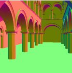 Camera Space Normals
视图空间法向量
Given we know that a normal is meant to be, er, normalised, we can throw away the z component and reconstruct it in the shader. All we need to know are the x and y components and the sign of the z and from that we can reconstruct the size of z by hand. There are actually several ways to encode normals into two components and Aras Pranckevicius has a great page presenting these concepts
假设我们知道一个归一化的法向量,我们就能够扔掉z分量然后在shader中重建它。我们只需要知道x,y分量,z分量可以通过手动重建出来。
Camera Space Linear Depth
The next section will explain why we actually need this, but another task we need to perform is to fill the remaining B & A channels of our texture with a linear scene depth. Not only can the depth buffer not be read directly/efficiently in DX9 anway, but we want our depths to be linear, so the accuracy of the 16 bits we have available is spread over the entire visible scene, not just the first metre or so. It is a simple matter to have a vertex shader output a depth at each point (code will follow, don’t worry), but the icky part will be breaking up this float value inside our pixelshader into effectly two unsigned 8 bit values so we can stuff these into the B & A channels.
下一段将解释为什么我们确实需要这么做,但是另一个我们需要执行的任务是用一个线性场景深度填充纹理剩下的B&A通道(及一个像素的后16位,前2位填了normal)。 在DX9技术中 不仅不能够直接/有效地读取深度缓冲区,而且我们还希望该深度值是一个线性的。所以我们的16位精确度,分散于整个场景,而不仅仅是头一米。用一个顶点shader输出每个点的深度值是一个简单的事情(下有代码可以参考),但是把像素shader中一个float值写入effect两个unsigned char中却是一件麻烦的事情,所以我们可以把这些值放到纹理的B&A通道中。
One detail not to be overlooked here is that a float value called “Depth” could be a very large, practically infinite number. We don’t need full resolution though, as our camera space scene will never show anything beyond the camera’s far clipping point. With this in mind, we normalise our depth value in the vertexshader by dividing the linear depth by the camera’s “far”, and pass that “far” value to the pixelshader so that it can be scaled back up again from the normalised value as it’s being sampled and reconstructed from the B & A texture channels.
一个不容忽视的细节是:一个float的深度值可能是非常大的,几乎无限多。我们不需要这么大的分辨率,因为我们的视图空间永远不可能超过相机的远截面。考虑到这点,我们在顶点shader中通过线性深度除以摄像机的可视范围来归一化我们的深度值,同时把这个 可视距离 传到像素shader中,以便让它把归一化的深度值还原成真实的深度值。
Reconstructing position from linear depth
从深度图中重建顶点的位置
MJP has a great page presenting this, so I’ll gloss over it here. The reason we need a camera space linear depth available is that if we also supply our pixel shader with projection/clip space rays to the corners of our viewing frustum (which we can pass in the vertices of our clip space quad), we can reconstruct an accurate 3D position anywhere in camera space just by reading this depth value and projecting along those rays.
这里有篇文章介绍了如何通过深度值重建位置。我们之所以需要一个视图空间的线性深度值的原因是:如果我们把裁剪空间中视点到视锥体顶点的射线提供给像素shader, 我们就能够通过深度值和这些射线 准确地重建视图空间内任一点的位置信息。
First Pass
Enough with the theory, lets get some code together. On this page, I’ll present everything required to get our first pass working. The output texture from this will be used in the next pass that will perform the actual SSAO calculations.
理论就讲到这里,下面让我们看看代码。在这一页,我将展示我们第一个pass所需要的所有东西,这个pass输出的纹理将会应用到下一个pass中,用来进行实时的SSAO计算
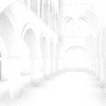
If you get this right, you should end up with something that looks like the picture to the left. Excuse the glowing, because we’re outputting values into the alpha channel, the options I had were to let the alpha control glowing or just dissappear altogether! By the way, the model I’m using is the “Sponza Atrium” as modelled by Marko Dabrovic and you can get it
如果你执行正确,你应该得到左图一样的结果。因为我们把值输出到了alpha通道,所以就必须选择是让alpha显示,还是都不显示。顺便说一下,我使用的模型是Marko Dabrovic制作的“Sponza Atrium”,你能够通过下面链接获得它。
I can’t show you our entire engine, so something you will have to do for yourself is make a rendering pass through your scene graph and draw everything into a render target texture setup with an RGBA 32 bit format. Instead of your usual shading setup for your scene’s materials though, you’ll need to do what follows as well. Sorry about the bunched spacing.
我不能告诉你我们引擎的细节,所以你得自己写一个渲染框架代替你通常的渲染,并且能够把物体绘制到一张32位的纹理上(RTT)。 下面代码将是你要做的。
// 生成一个矩阵用来把顶点坐标转换到视图空间 RZMatrix44 CamSpaceMatrix=ObjectToWorldSpaceMatrix*InverseCameraMatrix; // 转置 CamSpaceMatrix.Transpose(); // 设置shader常量 VShaderMgr->SetConstant(VSC_MODELTOCAMERA_MATRIX_R0,CamSpaceMatrix.ROW1); VShaderMgr->SetConstant(VSC_MODELTOCAMERA_MATRIX_R1,CamSpaceMatrix.ROW2); VShaderMgr->SetConstant(VSC_MODELTOCAMERA_MATRIX_R2,CamSpaceMatrix.ROW3); VShaderMgr->SetConstant(VSC_MODELTOCAMERA_MATRIX_R3,CamSpaceMatrix.ROW4); // 获取PS需要的常量 RZVector4 Vec; // 获取屏幕的宽高尺寸 tRECT Rect=View->GetArea(); Vec.VX=tF32(Rect.Width); Vec.VY=tF32(Rect.Height); // 获取视口的远近裁剪距离 Vec.VZ=View->GetNearClip(); Vec.VW=View->GetFarClip(); // 主要我们现在仅适用了vec的 w分量,其他部分还有其他作用 PShaderMgr->SetConstant(10,Vec);
Here’s the vertexshader code you should run during this pass:
这里是这个pass需要的顶点shader的代码:
struct OUT { float4 Position:POSITION0; float4 Data:TEXCOORD0; }; OUT main( float4 Position:POSITION0, float3 Normal:NORMAL0, uniform float4x4 Proj:register(VSC_PROJECTION_MATRIX_R0), uniform float4x4 ModelToCam:register(VSC_MODELTOCAMERA_MATRIX_R0)) { OUT Out; // 把顶点位置转化到Project空间 Out.Position=mul(Position,Proj); // Data.xyz 视图空间法向量 Out.Data.xyz=mul(Normal,(float3x3)ModelToCam); // 把Position转换到视空间 float4 CamPos=mul(Position,ModelToCam); // z/w 将作为线性深度坐标 Out.Data.w=CamPos.z/CamPos.w; return Out; }
And here’s the pixelshader code that goes with it:
这里是像素shader的代码:
float4 main( uniform float4 ViewData:register(c10) , float4 Params:TEXCOORD0):COLOR { float4 Data; // 还原深度值 float Depth = Params.w/ViewData.w; // 存储 RG通道的normal的x,y分量 Data.rg = normalize(Params.xyz).xy*0.5+0.5; // 通过BA通道存储深度值 Data.b = floor(Depth*255)/255; Data.a = floor((Depth-Data.b)*255*255)/255; return Data; }
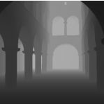
You should now have a source texture produced by the previous pass described on page 2. You will now need to set a render target of RGBA type again, and set your engine up to render into it. We’ll be supplying the previous pass texture (going to call this the data texture from here on out) into another pair of shaders along with some custom vertex data. What we get out from this will be a grey scale image that you can then use in your lighting pipeline for your ambient occlusion term.
你现在应该有一张由上面pass生成的纹理,我们将再需要另一张RGBA类型的纹理,并让你的引擎把场景渲染到它上面(RTT)。我们将会把前面渲染的纹理图片作为数据搭配给另一个shader使用。我们将会得到一张灰度图,然后你将可以在光照通道进行环境遮蔽(AO)处理。
I’m going to skip the algorithm description itself on how weactually use all these values to calculate the ambient occlusion term, but if you want to read more on the subject, the developers of StarCraft2 have produced an excellent paper describing their SSAO method along with other great stuff. My SSAO implementation matches theirs quite closely, albeit with getting my data from a far more streamlined place. I’ve also improved the self-occlusion artefact reduction somewhat.
我将跳过 如何用这些值来计算环境遮蔽 算法的描述。如果你想阅读更多关于算法的资料,你可以参考《星际争霸2》中关于SSAO及其他技术的论文S2008-Filion-McNaughton-StarCraftII.pdf,尽管我的程序还有很多可以精简的地方,但我的SSAO执行效率和他们的十分接近。 我事实上也稍微提高了遮蔽的效率。
So, let’s get some code together. The first thing we need to do is make a clip space quad that covers the screen. We’ll be running our SSAO shader over this shortly, but first we need to set it all up. In the vertices for our quad, we need rays to the corners of the viewing frustrum. As these get interpolated in the PS, we’ll have a ray for our current pixel position that points right at it from the camera’s position. Here’s how I set these vertices up. Note that the “Vertexs” parameter points to a locked dynamic VB in my engine, but in all honesty you can just a bit of system memory for this and draw using the draw prim *_UP methods, there’s only 4 vertices to upload.
那么,让我们来看下代码吧,我们首先需要做的是画一个覆盖整个屏幕的四边形。我们将在这个四边形上显示我们的SSAO效果。 在四边形的顶点处理阶段,我们需要计算视点到视锥体各顶点的射线。由于这些值可以在PS阶段插值得到,我们将能够通过当前像素的值和摄像机的位置得到一条射线。下面是我如何设置这些顶点。注意顶点参数指向我引擎中一个加锁的动态顶点缓冲区。但老实说,你只有4个顶点可以上传。
// 参数: HomoHack 是像素偏移。它默认为0.5,但可以用0.35 // 为了得到更好的采样点,我们采用0.35作为采样参数 tF32 HomogeniseX (tINT Xc,tF32 HomoHack) { // 把传入的屏幕坐标x转换到[-1,1]的齐次空间 return ((Xc-HomoHack)*(InvWidthF*2.0f))-1.0f; } tF32 HomogeniseY (tINT Yc,tF32 HomoHack) { // 把传入的屏幕坐标y转换到[-1,1]的齐次空间 return 1.0f-((Yc-HomoHack)*(InvHeightF*2.0f)); } tVOID BuildFrustrumQuad (tVOID *Verts,RZView* View) { // 此代码用来获取裁剪空间下的坐标。 // width, height为屏幕的宽、高 tF32 X1=HomogeniseX(0,0.35F); tF32 X2=HomogeniseX(Width,0.35F); tF32 Y1=HomogeniseY(0,0.35F); tF32 Y2=HomogeniseY(Height,0.35F); // 计算视锥体的四个顶角 tF32 FOV=View->GetCamera()->GetFOV(); tF32 Near=View->GetNearClip(); tF32 Far=View->GetFarClip(); tF32 NearH=2*RZMath::Tan(FOV)*Near; tF32 NearW=NearH; tF32 FarH=2*RZMath::Tan(FOV)*Far; tF32 FarW=FarH; tF32 NearX=NearW*0.5F; tF32 NearY=NearH*0.5F; tF32 FarX=FarW*0.5F; tF32 FarY=FarH*0.5F; // 我使用了一个通用顶点信息, 包含以下数据 // Position: float3 // UV : float2 // Ray: float4 tDATAVERT* Ptr=(tDATAVERT*)Verts; // TL: 左上角 Ptr[0].Pos.x=X1; Ptr[0].Pos.y=Y1; Ptr[0].Pos.z=0; Ptr[0].UV=RZCore::Core->VertexMgr->PackTexCoord(0,0); Ptr[0].Vec.x=-FarX; Ptr[0].Vec.y=FarY; Ptr[0].Vec.z=Far; Ptr[0].Vec.w=0; // TR:右上角 Ptr[1].Pos.x=X2; Ptr[1].Pos.y=Y1; Ptr[1].Pos.z=0; Ptr[1].UV=RZCore::Core->VertexMgr->PackTexCoord(1,0); Ptr[1].Vec.x=FarX; Ptr[1].Vec.y=FarY; Ptr[1].Vec.z=Far; Ptr[1].Vec.w=0; // BL:左下角 Ptr[2].Pos.x=X1; Ptr[2].Pos.y=Y2; Ptr[2].Pos.z=0; Ptr[2].UV=RZCore::Core->VertexMgr->PackTexCoord(0,1); Ptr[2].Vec.x=-FarX; Ptr[2].Vec.y=-FarY; Ptr[2].Vec.z=Far; Ptr[2].Vec.w=0; // BR :右下角 Ptr[3].Pos.x=X2; Ptr[3].Pos.y=Y2; Ptr[3].Pos.z=0; Ptr[3].UV=RZCore::Core->VertexMgr->PackTexCoord(1,1); Ptr[3].Vec.x=FarX; Ptr[3].Vec.y=-FarY; Ptr[3].Vec.z=Far; Ptr[3].Vec.w=0; }
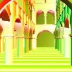
 Final Render
Vertex Shader:
struct OUT { float4 Position: POSITION0; float4 EyeVec:TEXCOORD0; float2 TexCoord:TEXCOORD1; }; OUT main ( float4 Position: POSITION0, float4 FrustPos:NORMAL0, float2 TexCoord:TEXCOORD0) { OUT Out; Out.Position=Position; Out.EyeVec=FrustPos; Out.TexCoord=TexCoord; return Out; }
像素shader:
float4 main( uniform float4 Params:register(c0), float4 EyeVec:TEXCOORD0, float2 UV:TEXCOORD1, uniform sampler SampleMap:register(s0), uniform sampler RandNorms:register(s1), uniform float4 SphereNorms[16]:register(c2)):COLOR { float Strength=Params.x; // 大约0.5 到 3 或者更大 float4 Sample=tex2D(SampleMap,UV); // 重建归一化的深度值 float Depth=(Sample.z+Sample.w/255); // AO特效的半径 float Rad=Params.y; // 还原摄像机的位置 float3 CamPos=EyeVec.xyz*Depth; // 按比例增加实际的深度值 Depth*=Params.w; // 还原视图空间的法向量 float3 Normal; Normal.xy=Sample.xy*2-1; Normal.z=-sqrt(1-dot(Normal.xy,Normal.xy)); // 获取一个随机法向量 float3 Ref=normalize((tex2D(RandNorms,UV*20).xyz*2.0)-1); float AO=0; // 生成一些用来检测的射线 for (int i=0;i<16;i++) { // 反射技巧,用以减少采样抖动 float3 Ray=Rad*reflect(SphereNorms.xyz,Ref); float RayDot=dot(normalize(Ray),Normal); // Reject samples that don't point away from the normal by a fair bit if (abs(RayDot)<0.5) continue; if (RayDot<0) Ray=-Ray; // 计算视图空间下的射线的表达式 float3 SamplePos=CamPos+Ray; // 返回到二维投影,以便我们能够在射线下取样。 float2 SampleUV=(SamplePos.xy/SamplePos.z)*0.5+0.5; SampleUV.y=1-SampleUV.y; float4 TestSample=tex2D(SampleMap,SampleUV); float TestDepth=(TestSample.z+TestSample.w/255)*Params.w; // Rebuild normal under the sample point if you want to work // that into your occlusion darkness term. I've found it adds little //float3 TestNormal; //TestNormal.xy=TestSample.xy*2-1; //TestNormal.z=-sqrt(1-dot(TestNormal.xy,TestNormal.xy)); // Accrue a level of AO based on how occluded we are, if at all float DepthDiff=(SamplePos.z-TestDepth); if (DepthDiff>0 && DepthDiff<Rad) AO+=1.0-smoothstep(0,Rad,DepthDiff); } float Val=Strength*AO/16; return float4(Val,Val,Val,1); }
That’s about it for now. Hope you find this useful in some small way…
这就是最终得到的效果,希望你能够从中发现一些有用的。
PS. A quick note about the pics attached to this article. To use this effect nicely in a real engine, you’ll want to blur the output using a standard separable Gaussian filter that respects depth changes to prevent bleed. (This might come in a later article). Because of all the blurring, there’s little visible degradation from doing both the passes described at half size, them sampling up during the blur. This gives a sizeable speed boost that’s well worth having. The pics don’t have the blur applied but they were still drawn half-size which explains why the dots look so chunky. After a good blur, this whole thing looks sweet!
附言: 附加在这篇论文上的截图下都有简短说明。 要想在引擎中很好地使用了
这项技术, 你肯能需要进行模糊处理,以便减少深度改变所引起的跳跃(这可能会出现在后面的文章中)。