OpenGL ES2学习笔记(10)-- Orthographic Projection
NDCs
到目前为止,我们定义的顶点坐标全部都坐落在[-1, +1]范围内,比如下面这四个点。这是因为OpenGL只知道如何处理这个范围内的顶点,这个范围被称作NDCs(Normalized-Device Coordinates)。
def vertices = [
// x     y
  -0.5f, -0.5f,
  -0.5f,  0.5f,
   0.5f,  0.5f,
   0.5f, -0.5f,
] as float[]
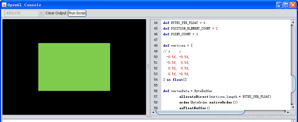
我们暂时可以这样理解:只有这个范围内的点会被OpenGL绘制到屏幕上,而且,无论最终的绘制区域是多大,OpenGL都把它当做一个正方形区域来处理。所以,如果上面四个点表示由两个三角形构成的矩形的话(Triangle Fan),它的长和宽分别是绘制区域长和宽的一半,如下图所示:
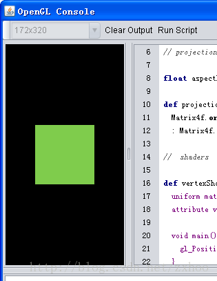
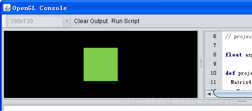
把绘制区域拉窄看看:
虚拟坐标系
从上面的两幅截图可以看出,直接使用NDC有很大的问题,因为最终绘制出来的图形会随绘制区域的不同而大相径庭。为了解决这个问题,我们不直接使用NDC,而是使用一个考虑了绘制区域纵横比(Aspect Ratio)的虚拟坐标空间(VCS,Virtual Coordinate Space),然后将VCS里的坐标转换到OpenGL所能理解的NDC上。完成这种变换的,是一种叫做Orthographic Projection的投影矩阵。
代码和效果
在OpenGL Console里执行下面的脚本:
import java.nio.ByteBuffer
import java.nio.ByteOrder
import javax.media.opengl.GL
import org.glob.math.Matrix4f

// projection matrix

float aspectRatio = (width>height ? width/height : height/width)

def projectionMatrix = (width > height) ?
  Matrix4f.orthoM(-aspectRatio, aspectRatio, -1f, 1f, -1f, 1f)
  : Matrix4f.orthoM(-1f, 1f, -aspectRatio, aspectRatio, -1f, 1f)

//  shaders

def vertexShaderCode = """
  uniform mat4 u_Matrix;
  attribute vec4 a_Position;

  void main() {
    gl_Position = u_Matrix * a_Position;
  }
"""

def fragmentShaderCode = """
  #ifdef GL_ES
  precision mediump float;
  #endif

  void main() {
    gl_FragColor = vec4(0.5, 0.8, 0.3, 1.0);
  }
"""

def shaderProgram = glob.compileAndLink(vertexShaderCode, fragmentShaderCode)
def aPositionLocation = shaderProgram.getAttribLocation("a_Position")
shaderProgram.use()
shaderProgram.getUniform("u_Matrix").setMatrix4fv(projectionMatrix.floats)

// vertex data

def BYTES_PER_FLOAT = 4
def POSITION_ELEMENT_COUNT = 2
def POINT_COUNT = 4

def vertices = [
// x     y
  -0.5f, -0.5f,
  -0.5f,  0.5f,
   0.5f,  0.5f,
   0.5f, -0.5f,
] as float[]

def vertexData = ByteBuffer
        .allocateDirect(vertices.length * BYTES_PER_FLOAT)
        .order(ByteOrder.nativeOrder())
        .asFloatBuffer()
vertexData.put(vertices)
vertexData.position(0)
gl.glVertexAttribPointer(aPositionLocation, POSITION_ELEMENT_COUNT, gl.GL_FLOAT, false, 0, vertexData)
gl.glEnableVertexAttribArray(aPositionLocation)

// draw triangle

gl.glClear(gl.GL_COLOR_BUFFER_BIT)
gl.glDrawArrays(gl.GL_TRIANGLE_FAN, 0, POINT_COUNT)
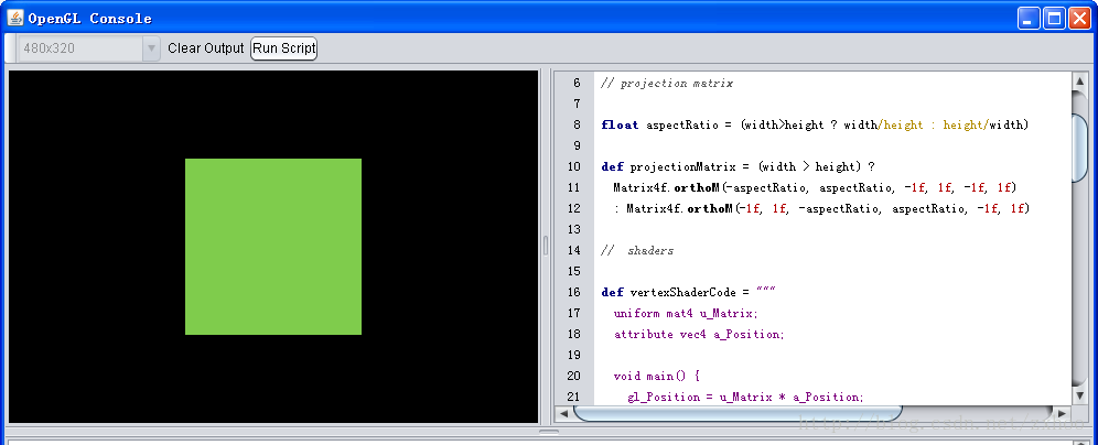
改变绘制区域的大小观察结果:
可以看到,无论绘制区域怎样变化,我们绘制的正方形始终都还是正方形 :)
代码解释
float aspectRatio = (width>height ? width/height : height/width)

def projectionMatrix = (width > height) ?
  Matrix4f.orthoM(-aspectRatio, aspectRatio, -1f, 1f, -1f, 1f)
  : Matrix4f.orthoM(-1f, 1f, -aspectRatio, aspectRatio, -1f, 1f)
首先根据绘制区域的宽度和高度(width和height是脚本的绑定变量,可以直接使用)算出Aspect Ratio(总是大于或等于1.0),然后算出Orthographic Projection。orthoM()方法如下所示:
    // Matrix4f.java
    public static Matrix4f orthoM(float left, float right, float bottom, float top, float near, float far) {
        return new Matrix4f(Order.ROW_MAJOR, new float[] {
            2/(right-left), 0,              0,             -(right+left)/(right-left),
            0,              2/(top-bottom), 0,             -(top+bottom)/(top-bottom),
            0,              0,              -2/(far-near), -(far+near)/(far-near),
            0,              0,              0,             1
        });
    }
假设绘制区域的宽和高分别是480和320的话,宽高比就是1.5,得到的虚拟坐标空间如下图所示:
如果宽是320,高是480的话,虚拟坐标空间将变成下面这样:
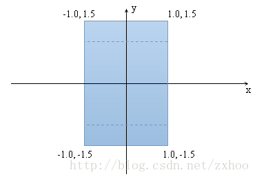
  uniform mat4 u_Matrix;
  attribute vec4 a_Position;

  void main() {
    gl_Position = u_Matrix * a_Position;
  }
Vertex Shader将投影矩阵和顶点位置向量相乘,最终得到了想要的效果。
