树莓派编译安装完整版本ROS
树莓派安装完整的ROS并不容易,博主东方赤龙花费了数天总结了安装编译的经验,否则很容易走弯路。
ROS官方论坛里面有安装教程, 但是很容易出错。尤其是Desktop版的ROS!
1. 安装环
树莓派B+, ROS Indigo, 16G TF卡,Raspbian OS
2. 安装装备
2.1 准备ROS代码仓库
- sudo sh -c 'echo "deb http://packages.ros.org/ros/ubuntu wheezy main" > /etc/apt/sources.list.d/ros-latest.list'
- wget https://raw.githubusercontent.com/ros/rosdistro/master/ros.key -O - | sudo apt-key add -
确保Raspbian OS 已经更新
- sudo apt-get update
- sudo apt-get upgrade
2.2 安装 bootstrap 依赖
- sudo apt-get install python-setuptools
- sudo easy_install pip
- sudo pip install -U rosdep rosinstall_generator wstool rosinstall
2.3 初始化 rosdep
- sudo rosdep init
- rosdep update
3. 编译ROS
3.1 创建workspace来编译ROS
- mkdir ~/ros_catkin_ws
- cd ~/ros_catkin_ws
接下来下载ROS代码,ROS 提供了两个代码包
1)ROS-Comm: 这是官方推荐的,但只包含基本的ROS通讯功能,没有navigation, TF, action, RViz等 GUI 工具
2) Desktop: 完整的ROS 功能,适合所有机器人应用。我们选择安装这个。
下面的命令下载并生产编译package列表,会很花时间
- rosinstall_generator desktop --rosdistro indigo --deps --wet-only --exclude roslisp --tar > indigo-desktop-wet.rosinstall
- wstool init -j8 src indigo-desktop-wet.rosinstall
如果中途下载中断,下面的命令会接着下载:
- wstool update -j 4 -t src
3.2 解决依赖
libconsole-bridge-dev, liburdfdom-headers-dev, liburdfdom-dev, liblz4-dev, 和 collada-dom-dev 这五个包并不在Raspbian里面,需要手工编译下载
创建新目录下载这5个包
- <span style="font-size:18px;">mkdir ~/ros_catkin_ws/external_src
- sudo apt-get install checkinstall cmake</span>
安装libconsole-bridge-dev:
- <span style="font-size:18px;">cd ~/ros_catkin_ws/external_src
- sudo apt-get install libboost-system-dev libboost-thread-dev
- git clone https://github.com/ros/console_bridge.git
- cd console_bridge
- cmake .
- sudo checkinstall make install</span>
接下来的两个问题连续选择'n', 否则会编译出错
安装liblz4-dev
- <span style="font-size:18px;">$ cd ~/ros_catkin_ws/external_src
- $ wget http://archive.raspbian.org/raspbian/pool/main/l/lz4/liblz4-1_0.0~r122-2_armhf.deb
- $ wget http://archive.raspbian.org/raspbian/pool/main/l/lz4/liblz4-dev_0.0~r122-2_armhf.deb
- $ sudo dpkg -i liblz4-1_0.0~r122-2_armhf.deb liblz4-dev_0.0~r122-2_armhf.deb</span>
安装liburdfdom-headers-dev
- <span style="font-size:18px;">$ cd ~/ros_catkin_ws/external_src
- $ git clone https://github.com/ros/urdfdom_headers.git
- $ cd urdfdom_headers
- $ cmake .
- $ sudo checkinstall make install</span>
当checkinstall询问是否改变安装选项时,选择[2],将名字从"urdfdom-headers" 改为 "liburdfdom-headers-dev"
接下来的两个问题连续选择'n', 否则会编译出错
安装liburdfdom-dev
- <span style="font-size:18px;">$ cd ~/ros_catkin_ws/external_src
- $ sudo apt-get install libboost-test-dev libtinyxml-dev
- $ git clone https://github.com/ros/urdfdom.git
- $ cd urdfdom
- $ cmake .
- $ sudo checkinstall make install</span>
当checkinstall询问是否改变安装选项时,选择[2],将名字从"urdfdom" 改为 "liburdfdom-dev"
接下来的两个问题连续选择'n', 否则会编译出错
安装collada-dom-dev
- <span style="font-size:18px;">$ cd ~/ros_catkin_ws/external_src
- $ sudo apt-get install libboost-filesystem-dev libxml2-dev
- $ wget http://downloads.sourceforge.net/project/collada-dom/Collada%20DOM/Collada%20DOM%202.4/collada-dom-2.4.0.tgz
- $ tar -xzf collada-dom-2.4.0.tgz
- $ cd collada-dom-2.4.0
- $ cmake .
- $ sudo checkinstall make install</span>
接下来的两个问题连续选择'n', 否则会编译出错
3.3 通过rosdep解决依赖
- <span style="font-size:18px;">$ cd ~/ros_catkin_ws
- $ rosdep install --from-paths src --ignore-src --rosdistro indigo -y -r --os=debian:wheezy</span>
3.4 开始编译ROS
$ sudo ./src/catkin/bin/catkin_make_isolated --install -DCMAKE_BUILD_TYPE=Release --install-space /opt/ros/indigo
常见错误:
编译过程中会编译180多个package并同时安装在/opt/ros/indigo目录,经常会报出 'urdf' 'collada_parser‘ ’collada_urdf' 这几个包出错而中断安装。 解决办法就是将这三个包从目录 ~/ros_catkin_ws/src/robot_model 目录中移出,再重新编译整个ROS. 最后单独建立一个workspace,将三个包放到src/robot_model 目录中。 再执行下面命令:
sudo ./src/catkin/bin/catkin_make_isolated --install -DCMAKE_BUILD_TYPE=Release --install-space /opt/ros/indigo
如果仍然报错,则需要重新一个一个安装 步骤3.2中的 liburdfdom-dev,liblz4-dev, 和 collada-dom-dev 包,每安装一个重新编译一遍,成功编译的包可以删除,直到最后都编译成功。
四轮机器人线性速率、角速度和电机PWM线性关系的定量分析
[+]
- ROS导航机器人驱动功能分析
- 1 ROS - 轮子驱动
- 2 轮子驱动 - ROS
-
- PWM 线性速度左右轮子速度和角速度的关系
- 左右轮子速度和PID控制
- PWM与轮子速度实验数据分析
- 左右轮速度差与角速度实验数据分析
-
- 带方向的线性速度和角速度
ROS中的机器人导航需要底层轮子驱动十分精确的对行进的速率和角速度进行控制。本文根据大量的实验数据进行图形化分析,找出线性速率、角速度和电机PWM线性关系,并得出计算公式。
1. ROS导航机器人驱动功能分析
ROS的navigation包内容十分丰富,并封装完整。开发机器人其实就是开发轮子驱动与ROS 进行通讯。这是一个双向通讯:
1.1 ROS -> 轮子驱动
ROS 在cmd_vel这个主题上发布Twist消息,这个消息包含的就是机器人的期望前进速度和转向速度。轮子驱动必须要精确的控制电机同时要以某个速度和某个角速度前进或后退。角速度就代表拐弯的弯度.
使用ctrl + alt + t 打开一个新的终端以后,输入如下命令,就可以查看Twist的消息类型了。
- rosmsg show geometry_msgs/Twist

Twist消息的结构,其中linear 的x就是代表前进方向的速度,单位为m/s。angular 的z就代表机器人的绕中心旋转的角速度,单位为 弧度/s (rad/s)。本文要研究这两个速度的关系。其余的4个成员可以忽略,它们对平面上的4轮机器人来说没有实际意义.
1.2 轮子驱动 -> ROS
电机执行的效果: 线性速度,角速度和机器人现在地图上的坐标需要实时反馈给ROS. 这是通过向odom主题发送nav_msgs/Odometry导航消息,报告角速度,线速度和巡航角度。
这部分请参照我的文章:ROS 学习系列 -- RViz中移动机器人来学习 URDF,TF,base_link, map,odom和odom 主题的关系
2. PWM, 线性速度,左右轮子速度和角速度的关系
机器人线性速度: RobotV
左右轮速度: LeftWheelV RightWheelV
角速度: YawRate
- RobotV = ( LeftWheelV + RightWheelV ) / 2 //公式1
- YawRate = delta_t * abs( LeftWheelV - RightWheelV ) //公式2
PWM 与轮子的关系:
- xxxxWheelV = PWM *factor + offset //公式3
在实际运行中发现,左右轮的性能因为硬件有所差异,所以 delta_t, factor, offset 对左右两边来讲是不一样的。所以它们各有一套参数。这些参数的确定是要通过大量的数据采集后进行分析得出来的。下面我们讨论如何确定公式2,3中的参数
3. 左右轮子速度和PID控制
PWM与轮子转速的关系并不是不变的,当电池放电一段时间后,要增大factor的值才能达到期望的速度。这就是PID的作用,PID要求给一个初始PWM值,上面的公式3就可以算出这个初始值,剩下就交给反馈调整了, ROS有个pid类。
4. PWM与轮子速度实验数据分析
PWM从20至100的区间平均取10个值,跑10轮。每轮前行1米,然后后退1米,记录前进后退两个速度。左右两轮各一套数据,每次这样得到了4个数据样本,总共40个,图表分析如下:

2。左下图 Backward left wheel 后退左轮
3。右上图 Forward right wheel 前行右轮
4。右下图 Backward right wheel 后退右轮
横坐标是PWM值,纵坐标是速度(m/s)
采样数据的结果非常完美,标准的线性关系图。同时也能看出来左右两轮确实有不一致的地方,但是前进后退的数据很统一。这样就可以测出factor, offset两个参数,左右两轮个一套。
5.左右轮速度差与角速度实验数据分析
公式2的分析比较复杂,但是一旦确定就不变了,除非改变环境。分析出delta_t转弯分为10种类型:
1,左轮不转,右轮PWM从20至100的区间平均取10个值,向前跑10轮。每轮跑360度,测出角速度和线速度。
2,右轮不转,左轮PWM从20至100的区间平均取10个值,向前跑10轮。每轮跑360度,测出角速度和线速度。
3,左轮比右轮转的慢,速度差逐渐加大取10个值,向前跑10轮。每轮跑360度,测出角速度和线速度。
4,右轮比左轮转的慢,速度差逐渐加大取10个值,向前跑10轮。每轮跑360度,测出角速度和线速度。
5,左轮向前,右轮向后,速度差逐渐加大取10个值,顺时针跑10轮。每轮跑360度,测出角速度和线速度。
6, 左轮不转,右轮PWM从20至100的区间平均取10个值,向后跑10轮。每轮跑360度,测出角速度和线速度。
7,右轮不转,左轮PWM从20至100的区间平均取10个值,向后跑10轮。每轮跑360度,测出角速度和线速度。
8,左轮比右轮转的慢,速度差逐渐加大取10个值,向后跑10轮。每轮跑360度,测出角速度和线速度。
9,右轮比左轮转的慢,速度差逐渐加大取10个值,向后跑10轮。每轮跑360度,测出角速度和线速度。
10,左轮向后,右轮向前,速度差逐渐加大取10个值,逆时针跑10轮。每轮跑360度,测出角速度和线速度。
图表分析如下:

左边图表从上向下对应旋转编号为 1,2,3,4,5
右边图表从上向下对应旋转编号为 6,7,8,9,10
横坐标为左右两轮速度差的绝对值,纵坐标为角速度,观察图像得出下面结论:
1。很明显前进和后退比例系数(斜率)不一样
2。它们向左向下的延长线都是穿过原点的,就是说速度差为0时,没有旋转,这个跟实际很匹配
3。左右两轮转弯性能无差异
4。第3,4行数据点向上平移到1,2行数据点,两组数据可以完全拼接成一条线保持相同的斜率
根据上面的数据可以推断出,公式2中的delta_t在前行和后退时是不一样的,10类转弯可以归纳为2种了。
6.带方向的线性速度和角速度
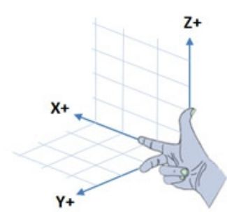
在ROS中,线性速度向后是负值,向前是正值。角速度方向的规定如图,它符合右手原则,右图逆时针方向就是正值,顺时针为负值。就是上面的左转为正,右转为副。

我们把方向考虑到公式1,2,3中,推导出代码可用的公式从而算出左右轮的速度 LeftWheelV, RightWheelV, 然后交给pid到树莓派执行。从而达到精确的同时控制线性速度和角速度。其中RobotV 和 YawRate是ROS下发的命令,程序运行时就是已知量。
- RobotV = ( LeftWheelV + RightWheelV ) / 2 //公式1
- YawRate = delta_t * abs( LeftWheelV - RightWheelV ) //公式2
当 LeftWheelV 大于 RightWheelV时 是右转,此时YawRate为负,反之为正。公式2中的abs决定值可以去掉了,变成公式4
- YawRate = delta_t * ( RightWheelV - LeftWheelV ) //公式4
- YawRate / delta_t = RightWheelV - LeftWheelV
公式1不变,简单变换一下
- RobotV = ( LeftWheelV + RightWheelV ) / 2 //公式1
- RobotV * 2 = LeftWheelV + RightWheelV
合并公式1 和 4,初中的二元一次方程,得出:
- YawRate / delta_t + RobotV * 2 = RightWheelV * 2
- 两边除2
- YawRate / delta_t / 2 + RobotV = RightWheelV
- 左右互换
- RightWheelV = RobotV + YawRate / delta_t / 2
- LeftWheelV = RobotV * 2 - ( YawRate / delta_t / 2 + RobotV ) = RobotV - YawRate / delta_t / 2
Ros 的base_control 的C++代码
- #include "ros/ros.h"
- #include "std_msgs/String.h"
- #include <wiringPi.h>
- #include <sstream>
- #include "boost/shared_ptr.hpp"
- #include <geometry_msgs/Twist.h>
- #include "RunVelocity.h"
- boost::shared_ptr<RunVelocity> m_leftwheel;
- boost::shared_ptr<RunVelocity> m_rightwheel;
- void cmd_vel_callback(const geometry_msgs::Twist& vel_cmd)
- {
- double LeftWheelV, RightWheelV;
- double RobotV = vel_cmd.linear.x;
- double YawRate = vel_cmd.angular.z;
- double delta_t = RobotV > 0 ? 5.9 : 4.45;
- RightWheelV = RobotV + YawRate / delta_t / 2 ;
- LeftWheelV = RobotV - YawRate / delta_t / 2 ;
- m_leftwheel->RunSpeedCommand(LeftWheelV);
- m_rightwheel->RunSpeedCommand(RightWheelV);
- }
- int main(int argc, char **argv)
- {
- ros::init(argc, argv, "base_control");
- ros::NodeHandle n;
- ros::Subscriber cmd_vel_sub = n.subscribe("/cmd_vel", 10, cmd_vel_callback);
- // 树莓派gpio控制轮子
- wiringPiSetup();
- int left_forward, left_backward, right_forward, right_backward;
- n.param("left_forward", left_forward, 1);
- n.param("left_backward", left_backward, 4);
- n.param("right_forward", right_forward, 6);
- n.param("right_backward", right_backward, 5);
- m_leftwheel = boost::shared_ptr<RunVelocity>(new RunVelocity(n, left_forward, left_backward));
- m_rightwheel = boost::shared_ptr<RunVelocity>(new RunVelocity(n, right_forward, right_backward));
- ROS_INFO("ready to run on /cmd_vel");
- ros::spin();
- }
HMC5883L 电子指南针用树莓派进行磁场干扰过滤 校准
本文适合所有的电子指南针校准,不仅限于 HMC5883L. 硬件的连接和树莓派的搭建以后再写。
本文仅限于固定强度和方向磁场干扰的过滤,例如机器人自身其它设备产生的磁场。但对于环境如扩音器喇叭等磁场干扰无效.
首先进行X Y 方向的校准,将芯片平放固定到一个水平面,这时大地磁场是近似平行XY平面的,绕Z轴慢速的转动XY平面,电子指南针HMC5883L会测量出圆周内大地磁场的强度+固定干扰磁场。而固定磁场的强度就是所有测量值的平均值。
- #!/usr/bin/python
- import smbus
- import time
- import math
- bus = smbus.SMBus(0)
- address = 0x1e
- def read_byte(adr):
- return bus.read_byte_data(address, adr)
- def read_word(adr):
- high = bus.read_byte_data(address, adr)
- low = bus.read_byte_data(address, adr+1)
- val = (high << 8) + low
- return val
- def read_word_2c(adr):
- val = read_word(adr)
- if (val >= 0x8000):
- return -((65535 - val) + 1)
- else:
- return val
- def write_byte(adr, value):
- bus.write_byte_data(address, adr, value)
- write_byte(0, 0b01110000) # Set to 8 samples @ 15Hz
- write_byte(1, 0b00100000) # 1.3 gain LSb / Gauss 1090 (default)
- write_byte(2, 0b00000000) # Continuous sampling
- scale = 0.92
- for i in range(0,500):
- x_out = read_word_2c(3)
- y_out = read_word_2c(7)
- z_out = read_word_2c(5)
- bearing = math.atan2(y_out, x_out)
- if (bearing < 0):
- bearing += 2 * math.pi
- print x_out, y_out, (x_out * scale), (y_out * scale)
- time.sleep(0.1)
运行上面的程序,在50秒内不停地旋转装有芯片的水平面,360度的缓慢旋转,一定要保证水平面稳定,否则会得到很多奇怪的干扰数据。
- sudo ./compass-test.py > compass-plot.dat
将输出结果导入到compas-plot.dat文件里面。接下来我们用GNUPlot来看一下数据结果,以每对儿X Y为坐标的图形效果。
- set terminal wxt persist size 800,800 background'#000000'
- set style line99 linecolor rgb "#ffffff" linetype 0 linewidth 2
- set key topright textcolor linestyle 99
- set gridlinestyle 99
- set borderlinestyle 99
- plot filenameusing 1:2 title "Raw compass values" linecolor rgb "green"
将上面命令文本保存到 gnuplot-compass.plg并执行下面的命令,可以看到图形:
- gnuplot -e "filename='compass-plot.dat'"gnuplot-compass.plg

这时我们可以看到图形的圆心不是在 0,0 点
把上面程序的for循环内容更换成下面的代码,运行50秒不停地手动旋转水平面,
- minx = 0
- maxx = 0
- miny = 0
- maxy = 0
- for i in range(0,500):
- x_out = read_word_2c(3)
- y_out = read_word_2c(7)
- z_out = read_word_2c(5)
- if x_out < minx:
- minx=x_out
- if y_out < miny:
- miny=y_out
- if x_out > maxx:
- maxx=x_out
- if y_out > maxy:
- maxy=y_out
- #print x_out, y_out, (x_out * scale), (y_out * scale)
- time.sleep(0.1)
- print "minx: ", minx
- print "miny: ", miny
- print "maxx: ", maxx
- print "maxy: ", maxy
- print "x offset: ", (maxx + minx) / 2
- print "y offset: ", (maxy + miny) / 2
这一次会输出下面的值:
- minx: -216
- miny: -193
- maxx: 197
- maxy: 213
- x offset: -10
- y offset: 10
把输出的偏移加到程序当中,第一段程序的读取值的代码换成下面:
- x_offset = -10
- y_offset = 10
- x_out = (read_word_2c(3) - x_offset) * scale
- y_out = (read_word_2c(7) - y_offset) * scale
- z_out = (read_word_2c(5)) * scale
Z 方向的校准同上面的方法,只是要把XZ平面固定到水平面上做同样的事情而已。
网上有好多文章介绍如何从HMC5883L电子罗盘中获取旋转的角度。但是其中有个重要的参数Declination并没有太多介绍,而且该参数是必要的。
- rom i2clibraries import i2c_hmc5883l
- hmc5883l = i2c_hmc5883l.i2c_hmc5883l(0)
- hmc5883l.setContinuousMode()
- hmc5883l.setDeclination(9,54)
- print(hmc5883l)
罗盘要确定方向北面是靠磁场来确定的,北向有两个标准:
World Magnetic Model (WMM) 是磁场的正北
International Geomagnetic Reference Field (IGRF) 也称为Ture North,是地图上的正北
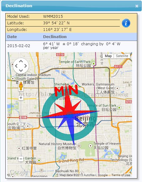
但事实上这两个北向是有偏差的,这个偏差就叫Declination,就是下图中的橙色扇区角度。它的值随着地域和时间而变化,我们可以访问这里来查询这个值。英文介绍视频,它们都是由美国国家地理数据中心提供的,如果打不开,只能自己想办法了:)

下面的图像显示整个地球范围内,Declination分布的规律,每一个等高线上的Declination 是相同的,中间的黄绿线是0,也就是磁场北和地理北完全重合。红线为正值,蓝线为负值。

下面是网站页面,可以看到北京的正北和磁场的北是有个偏角的,这就是Declination.时间是2015 - 02 -02
RViz中移动机器人来学习 URDF,TF,base_link, map,odom和odom 主题的关系
前面已经介绍了如何使用URDF建造机器人小车并显示在Rviz的仿真环境里面,但是小车是静止的。下面介绍如何让它在Rviz里面动起来,并理清URDF,TF 和 odom 的关系。
1. ROS中base_link, odom, fixed_frame, target_frame和虚拟大地图map的关系
一般在urdf文件中都要定义base_link,它代表了机器人的主干,其它所有的frame都是相对于base_link定义并粘在一起的。它们一起相对于大地图map移动,让机器人移动就是向tf发布 geometry_msgs::TransformStamped 消息通知ros base_linke相对于map的tf转换关系。先看一下这几个概念在ros中的定义:
map
map是虚拟世界中的固定frame, 它的Z轴指向正上方,也就是天空。一个时间点上移动机器人的姿态相对于map不应该出现明显的漂移。如果一个map是不连续稳定的那就意味着机器人的位置在任何一个时间点上都会是变化的。
一般激光地位仪等设备会连续的计算map的位置因而造成它的不稳定性,这也使它不能成为一个好的参照体frame.
odom
odom是一个很好的固定世界参照frame.机器人的姿态相对odom而言是随时间是经常可变,所以在长远中它不是一个好的全局参照系。但在某一时间点而言它相对机器人的位置是不变的。
典型的 odom frame 是通过运动源来计算出来的, 例如轮子运动,视觉偏移等.
odom frame 的准确性使它在局部参照系中是很有用的。但是不适合作全局参照frame.
base_link
base_link参照系紧紧粘在移动机器人基座上的任何一个位置和角度。
各个Frames的关系
frame之间是按树状结构组织的。所以每个frame只有一个父节点和任意多个子节点。 上述几个frame的关系:
map --> odom --> base_link
Frame Authorities
odom到base_link的坐标转换是从运动源计算出来广播的。
map到base_link的坐标转换是被定位模块计算出来的. 但定位模块并不发布map到base_link的转换. 相反它先接受从odom到base_link的转换, 再计算并广播map到odom的位置转换关系。
fixed_frame
RViz中认定的大世界就是fixed_frame
target_frame
Rviz中视觉跟踪的frame是 target_frame
2. RViz如何动态确定各个frame之间的坐标转换
先看一下启动RViz的launch文件,里面定要了服务于RViz的参数和node
- <launch>
- <arg name="model" />
- <arg name="gui" default="False" />
- <param name="robot_description" textfile="$(arg model)" />
- <param name="use_gui" value="$(arg gui)"/>
- <node name="joint_state_publisher" pkg="joint_state_publisher" type="joint_state_publisher" />
- <node name="robot_state_publisher" pkg="robot_state_publisher" type="state_publisher" />
- <node name="rviz" pkg="rviz" type="rviz" args="-d $(find sp1s)/urdf.rviz" required="true" />
- </launch>
"joint_state_publisher"节点获取urdf里面定义的rotate link并发布坐标转换给tf.否则会显示warning. 注意: "joint_state_publisher" 是Python写的,只支持ascii编码,不支持Unicode,如果发现RViz报告下面错误:
"No transform from [front_left] to [base_link]"
那就是因为urdf文件是Unicode编码的。
3. geometry_msgs/TransformStamped 消息的作用和机构
geometry_msgs/TransformStamped 就是通知ROS 两个frame之间的tf转换关系。当两个frame之间关系经常变化,如轮子移动,手臂关节移动等,则需要编写node来实时发布。查看该消息结构:- <span style="font-size:18px;">rosmsg show -r geometry_msgs/TransformStamped
- # This expresses a transform from coordinate frame header.frame_id
- # to the coordinate frame child_frame_id
- #
- # This message is mostly used by the
- # <a href="http://www.ros.org/wiki/tf">tf</a> package.
- # See its documentation for more information.
- Header header
- string child_frame_id # the frame id of the child frame
- Transform <strong><span style="color:#FF0000;">transform</span></strong>
- </span>
- rosmsg show -r geometry_msgs/Transform
- # This represents the transform between two coordinate frames in free space.
- Vector3 <strong><span style="color:#FF0000;">translation</span></strong>
- Quaternion rotation
- rosmsg show -r Vector3
- [geometry_msgs/Vector3]:
- # This represents a vector in free space.
- float64 x
- float64 y
- float64 z
4. RViz中如何定义 base_link 和 odom 之间的 tf 坐标转换
要移动机器人,就需要向tf发布geometry_msgs/TransformStamped 消息通知ros base_linke相对于map的tf转换关系,也就是说告诉ROS运动的base_link相对于不动的odom位置偏移。这里的odom frame并不能定义在urdf文件里面,它是一个虚拟的。我们只需要RViz知道fixed_frame就是odom就可以了。所以在urdf.rviz文件中这样定义虚拟odom:
- <span style="font-size:18px;">Global Options:
- Background Color: 48; 48; 48
- Fixed Frame: <strong><span style="color:#FF0000;">/odom</span></strong>
- Target Frame: <Fixed Frame>
- Frame Rate: 30</span>
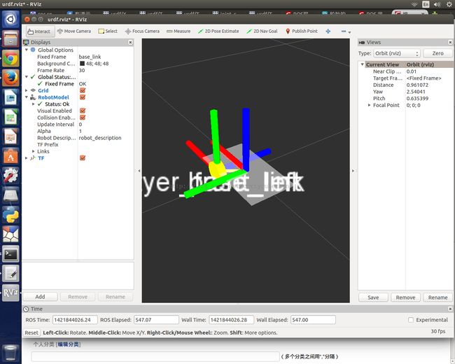
如果现在启动 RViz来观察机器人:
- <span style="font-size:18px;">roslaunch sp1s display.launch model:=urdf/sp1s.urdf </span>
肯定会得到错误警告,而且RViz中无法显示完整的机器人:
"No transform from [odom] to [base_link]"
这个错误很容易理解,没有任何地方定义odom和base_link之间的tf关系,他们之间是连续变化的,我们当然不能在任何地方写固定偏移量定义tf transform.
但是我们可以写一个node来不断的发送geometry_msgs/TransformStamped消息。被发送对象就是tf。 ROS官方有个实例完整代码如何发布odom到base_link的变换,代码实例直接拷贝并在本地编译。这个例子不断向odom主题发送消息更改odom与base_link之间的位移,位移的轨迹就是一个圆周。这个node名字叫 odom_publisher. 它其实做了两件事情:
1. 向 tf 发送geometry_msgs/TransformStamped 消息, 就是让机器人运动起来。
2. 向odom主题发送nav_msgs/Odometry导航消息,报告角速度,线速度和巡航角度。这部分代码相对本文来讲不是必须的。
同"joint_state_publisher" node一样,“ odom_publisher”需要在RViz启动之前启动,添加它的启动项。修改后的dispaly.launch文件:
- <launch>
- <arg name="model" />
- <arg name="gui" default="False" />
- <param name="robot_description" textfile="$(arg model)" />
- <param name="use_gui" value="$(arg gui)"/>
- <strong><span style="color:#FF0000;"><node name="odom_publisher" pkg="sp1s" type="odom_publisher" /></span></strong>
- <node name="joint_state_publisher" pkg="joint_state_publisher" type="joint_state_publisher" />
- <node name="robot_state_publisher" pkg="robot_state_publisher" type="state_publisher" />
- <node name="rviz" pkg="rviz" type="rviz" args="-d $(find sp1s)/urdf.rviz" required="true"/>
- lt;/launch></span>
再次打开RViz:
- roslaunch sp1s display.launch model:=urdf/sp1s.urdf
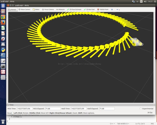
这次就看到机器人在地图空间中做规则的圆周运动了! 因为RViz收到了odom_publisher向tf发送的坐标转换内容。
4. RViz中观察移动轨迹
“ odom_publisher”中还向 odom主题发布了nav_msgs/Odometry导航消息,这样就可以在RViz中显示运动轨迹了。在RViz中点击 'add',选中Odometry,配置该dispaly的topic为 "odom" 就可以看到不断变化的运动轨迹了。这是因为nav_msgs/Odometry中包含了线速度,角速度和巡航角度,所以RViz可以显示出来。
5.odom frame和 odom topic
这两个完全是不同的东西,很容易混淆。一个是地图上的一个参照系,一个是topic用来接收导航输入的。名字一样,纯属巧合!
使用urdf创建机器人模型在Rviz中3D观察 之二 joint 使用
我们接着上文 ROS 学习系列 -- 使用urdf创建机器人模型在Rviz中3D观察 之一 link使用继续完成创建带四个可以转动轮子的双层小车。
一 建立可以转动的joint
- <span style="font-size:18px;"><?xml version="1.0"?>
- <robot name="sp1s">
- <link name="base_link">
- <visual>
- <geometry>
- <box size="0.27 .15 .003"/>
- </geometry>
- <material name="white">
- <color rgba="1 1 1 .5"/>
- </material>
- </visual>
- </link>
- <link name="front_left">
- <visual>
- <geometry>
- <cylinder length=".025" radius="0.034"></cylinder>
- </geometry>
- <material name="yellow">
- <color rgba="1 1 0 1"/>
- </material>
- </visual>
- </link>
- <joint name="base_to_front_left" type="<span style="color:#FF0000;"><strong>continuous</strong></span>">
- <origin rpy="1.57075 0 0" xyz="0.06 0.064 -0.011"/>
- <parent link="base_link"/>
- <child link="front_left"/>
- <axis xyz="0 0 1"/>
- </joint>
- </robot></span>
1. 将joint的类型改为"continuous" 这样front_left相对base_link就是一个转动的装置
2. 转动的位置就是由 origin定义的,它同时定义了tyer_front_left的新原点,之前它的原点默认就是base_link的原点
xyz 是相对相对parant base_link原点的偏移, 它把轮子移动到了左前方。其中:
z = -0.011m = 6.8cm/2-4.5cm,保证轮子是在地上的
y = 0.064m = 15cm/2 - 2.5cm / 2 (轮子厚度) + offset
pry 是分别以 x y z 轴为中心转动的角度(弧度制) 1.57075 就是90度。 围绕x轴旋转90度轮子就竖了起来。
3. axis重新定义转动轴在原点的方向,它是一个矢量,只指示方向,它们必须满足 x * x + y * y + z * z = 1 原点Z轴已经被旋转90度变成水平方向,所以这里定义Z轴方向为转动方向
二 重复添加四个轮子
其它三个轮子只有origin正负值的调整
- <span style="font-size:18px;"><?xml version="1.0"?>
- <robot name="sp1s">
- <link name="base_link">
- <visual>
- <geometry>
- <box size="0.27 .15 .003"/>
- </geometry>
- <material name="white">
- <color rgba="1 1 1 .5"/>
- </material>
- </visual>
- </link>
- <link name="tyer_front_left">
- <visual>
- <geometry>
- <cylinder length=".025" radius="0.034"></cylinder>
- </geometry>
- <material name="yellow">
- <color rgba="1 1 0 1"/>
- </material>
- </visual>
- </link>
- <link name="tyer_front_right">
- <visual>
- <geometry>
- <cylinder length=".025" radius="0.034"></cylinder>
- </geometry>
- <material name="yellow">
- <color rgba="1 1 0 1"/>
- </material>
- </visual>
- </link>
- <link name="tyer_back_left">
- <visual>
- <geometry>
- <cylinder length=".025" radius="0.034"></cylinder>
- </geometry>
- <material name="yellow">
- <color rgba="1 1 0 1"/>
- </material>
- </visual>
- </link>
- <link name="tyer_back_right">
- <visual>
- <geometry>
- <cylinder length=".025" radius="0.034"></cylinder>
- </geometry>
- <material name="yellow">
- <color rgba="1 1 0 1"/>
- </material>
- </visual>
- </link>
- <joint name="base_to_front_left" type="continuous">
- <origin rpy="1.57075 0 0" xyz="0.06 0.064 -0.011"/>
- <parent link="base_link"/>
- <child link="tyer_front_left"/>
- <axis xyz="0 0 1"/>
- </joint>
- <joint name="base_to_front_right" type="continuous">
- <origin rpy="1.57075 0 0" xyz="0.06 -0.064 -0.011"/>
- <parent link="base_link"/>
- <child link="tyer_front_right"/>
- <axis xyz="0 0 1"/>
- </joint>
- <joint name="base_to_back_left" type="continuous">
- <origin rpy="1.57075 0 0" xyz="-0.06 0.064 -0.011"/>
- <parent link="base_link"/>
- <child link="tyer_back_left"/>
- <axis xyz="0 0 1"/>
- </joint>
- <joint name="base_to_back_right" type="continuous">
- <origin rpy="1.57075 0 0" xyz="-0.06 -0.064 -0.011"/>
- <parent link="base_link"/>
- <child link="tyer_back_right"/>
- <axis xyz="0 0 1"/>
- </joint>
- </robot>
- </span>

三 添加四个柱子
上下层的四个角上是高3cm的柱子. 在上面urdf的基础上再添加下面的内容添加一个左前方的柱子。
- <span style="font-size:18px;"> <link name="pillar_front_left">
- <visual>
- <geometry>
- <cylinder length=".03" radius="0.0025"></cylinder>
- </geometry>
- <origin xyz="0 0 0.015"/>
- <material name="silver">
- <color rgba=".86 .86 .86 1"/>
- </material>
- </visual>
- </link>
- <joint name="base_to_pillar_front_left" type="fixed">
- <origin xyz="0.13 0.07 0.0015"/>
- <parent link="base_link"/>
- <child link="pillar_front_left"/>
- </joint></span>
1. 柱子不转动,所以joint的类型为 fixed
2. joint里面定义改变了柱子的原点为 xyz="0.13 0.07 0.0015" 是相对base_link的
3. link里面也定义了原点为xyz="0 0 0.015", 这里只是显示上的偏移,它相对于joint里面定义的原点,但并不改变joint里面定义的物理原点
4. 接下来重复加三个柱子,详见最后一段的urdf定义
四 添加上层
上层和base_link一样,它们之间通过fixed joint相连。在 Z 轴方向上偏移3cm。
- <link name="top_link">
- <visual>
- <geometry>
- <box size="0.27 .15 .003"/>
- </geometry>
- <material name="white">
- <color rgba="1 1 1 .5"/>
- </material>
- </visual>
- </link>
- <joint name="base_to_top" type="fixed">
- <origin xyz="0 0 0.03"/>
- <parent link="base_link"/>
- <child link="top_link"/>
- </joint>
五 完整的urdf
- <?xml version="1.0"?>
- <robot name="sp1s">
- <link name="base_link">
- <visual>
- <geometry>
- <box size="0.27 .15 .003"/>
- </geometry>
- <material name="white">
- <color rgba="1 1 1 .5"/>
- </material>
- </visual>
- </link>
- <link name="tyer_front_left">
- <visual>
- <geometry>
- <cylinder length=".025" radius="0.034"></cylinder>
- </geometry>
- <material name="yellow">
- <color rgba="1 1 0 1"/>
- </material>
- </visual>
- </link>
- <link name="tyer_front_right">
- <visual>
- <geometry>
- <cylinder length=".025" radius="0.034"></cylinder>
- </geometry>
- <material name="yellow">
- <color rgba="1 1 0 1"/>
- </material>
- </visual>
- </link>
- <link name="tyer_back_left">
- <visual>
- <geometry>
- <cylinder length=".025" radius="0.034"></cylinder>
- </geometry>
- <material name="yellow">
- <color rgba="1 1 0 1"/>
- </material>
- </visual>
- </link>
- <link name="tyer_back_right">
- <visual>
- <geometry>
- <cylinder length=".025" radius="0.034"></cylinder>
- </geometry>
- <material name="yellow">
- <color rgba="1 1 0 1"/>
- </material>
- </visual>
- </link>
- <joint name="base_to_front_left" type="continuous">
- <origin rpy="1.57075 0 0" xyz="0.06 0.064 -0.011"/>
- <parent link="base_link"/>
- <child link="tyer_front_left"/>
- <axis xyz="0 0 1"/>
- </joint>
- <joint name="base_to_front_right" type="continuous">
- <origin rpy="1.57075 0 0" xyz="0.06 -0.064 -0.011"/>
- <parent link="base_link"/>
- <child link="tyer_front_right"/>
- <axis xyz="0 0 1"/>
- </joint>
- <joint name="base_to_back_left" type="continuous">
- <origin rpy="1.57075 0 0" xyz="-0.06 0.064 -0.011"/>
- <parent link="base_link"/>
- <child link="tyer_back_left"/>
- <axis xyz="0 0 1"/>
- </joint>
- <joint name="base_to_back_right" type="continuous">
- <origin rpy="1.57075 0 0" xyz="-0.06 -0.064 -0.011"/>
- <parent link="base_link"/>
- <child link="tyer_back_right"/>
- <axis xyz="0 0 1"/>
- </joint>
- <link name="pillar_front_left">
- <visual>
- <geometry>
- <cylinder length=".03" radius="0.0025"></cylinder>
- </geometry>
- <origin xyz="0 0 0.015"/>
- <material name="silver">
- <color rgba=".86 .86 .86 1"/>
- </material>
- </visual>
- </link>
- <link name="pillar_front_right">
- <visual>
- <geometry>
- <cylinder length=".03" radius="0.0025"></cylinder>
- </geometry>
- <origin xyz="0 0 0.015"/>
- <material name="silver">
- <color rgba=".86 .86 .86 1"/>
- </material>
- </visual>
- </link>
- <link name="pillar_back_left">
- <visual>
- <geometry>
- <cylinder length=".03" radius="0.0025"></cylinder>
- </geometry>
- <origin xyz="0 0 0.015"/>
- <material name="silver">
- <color rgba=".86 .86 .86 1"/>
- </material>
- </visual>
- </link>
- <link name="pillar_back_right">
- <visual>
- <geometry>
- <cylinder length=".03" radius="0.0025"></cylinder>
- </geometry>
- <origin xyz="0 0 0.015"/>
- <material name="silver">
- <color rgba=".86 .86 .86 1"/>
- </material>
- </visual>
- </link>
- <joint name="base_to_pillar_front_left" type="fixed">
- <origin xyz="0.13 0.07 0.0015"/>
- <parent link="base_link"/>
- <child link="pillar_front_left"/>
- </joint>
- <joint name="base_to_pillar_front_right" type="fixed">
- <origin xyz="-0.13 0.07 0.0015"/>
- <parent link="base_link"/>
- <child link="pillar_front_right"/>
- </joint>
- <joint name="base_to_pillar_back_left" type="fixed">
- <origin xyz="0.13 -0.07 0.0015"/>
- <parent link="base_link"/>
- <child link="pillar_back_left"/>
- </joint>
- <joint name="base_to_pillar_back_right" type="fixed">
- <origin xyz="-0.13 -0.07 0.0015"/>
- <parent link="base_link"/>
- <child link="pillar_back_right"/>
- </joint>
- <link name="top_link">
- <visual>
- <geometry>
- <box size="0.27 .15 .003"/>
- </geometry>
- <material name="white">
- <color rgba="1 1 1 .5"/>
- </material>
- </visual>
- </link>
- <joint name="base_to_top" type="fixed">
- <origin xyz="0 0 0.03"/>
- <parent link="base_link"/>
- <child link="top_link"/>
- </joint>
- </robot>
