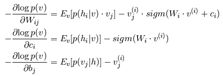
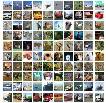
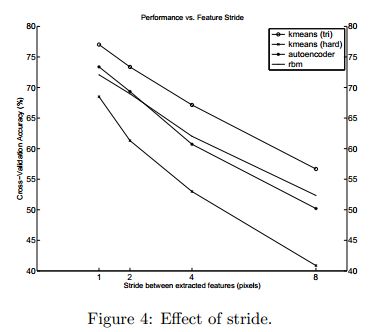
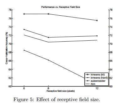
网上某位牛人的deep learning学习笔记汇总
目录(?)[-]
- 作者tornadomeet 出处httpwwwcnblogscomtornadomeet 欢迎转载或分享但请务必声明文章出处
- Deep learning一基础知识_1
- Deep learning二linear regression练习
- Deep learning三Multivariance Linear Regression练习
- Deep learning四logistic regression练习
- Deep learning五regularized线性回归练习
- Deep learning六regularized logistic回归练习
- Deep learning七基础知识_2
- Deep learning八Sparse Autoencoder
- Deep learning九Sparse Autoencoder练习
- Deep learning十PCA和whitening
- Deep learning十一PCA和whitening在二维数据中的练习
- Deep learning十二PCA和whitening在二自然图像中的练习
- Deep learning十三Softmax Regression
- Deep learning十四Softmax Regression练习
- Deep learning十五Self-Taught Learning练习
- Deep learning十六deep networks
- Deep learning十七Linear DecodersConvolution和Pooling
- Deep learning十八关于随机采样
- Deep learning十九RBM简单理解
- Deep learning二十无监督特征学习中关于单层网络的分析
- Deep learning二十一随机初始化在无监督特征学习中的作用
- Deep learning二十二linear decoder练习
- Deep learning二十三Convolution和Pooling练习
- Deep learning二十四stacked autoencoder练习
- Deep learning二十五Kmeans单层网络识别性能
- Deep learning二十六Sparse coding简单理解
- Deep learning二十七Sparse coding中关于矩阵的范数求导
- Deep learning二十八使用BP算法思想求解Sparse coding中矩阵范数导数
- Deep learning二十九Sparse coding练习
- Deep learning三十关于数据预处理的相关技巧
- Deep learning三十一数据预处理练习
- Deep learning三十二基础知识_3
- Deep learning三十三ICA模型
- Deep learning三十四用NN实现数据的降维
- Deep learning三十五用NN实现数据降维练习
- Deep learning三十六关于构建深度卷积SAE网络的一点困惑
- Deep learning三十七Deep learning中的优化方法
- Deep learning三十八Stacked CNN简单介绍
- Deep learning三十九ICA模型练习
作者:tornadomeet 出处:http://www.cnblogs.com/tornadomeet 欢迎转载或分享,但请务必声明文章出处。
Deep learning:一(基础知识_1)
前言:
最近打算稍微系统的学习下deep learing的一些理论知识,打算采用Andrew Ng的网页教程UFLDL Tutorial,据说这个教程写得浅显易懂,也不太长。不过在这这之前还是复习下machine learning的基础知识,见网页:http://openclassroom.stanford.edu/MainFolder/CoursePage.php?course=DeepLearning。内容其实很短,每小节就那么几分钟,且讲得非常棒。
教程中的一些术语:
Model representation:
其实就是指学习到的函数的表达形式,可以用矩阵表示。
Vectorized implementation:
指定是函数表达式的矢量实现。
Feature scaling:
指是将特征的每一维都进行一个尺度变化,比如说都让其均值为0等。
Normal equations:
这里指的是多元线性回归中参数解的矩阵形式,这个解方程称为normal equations.
Optimization objective:
指的是需要优化的目标函数,比如说logistic中loss function表达式的公式推导。或者多元线性回归中带有规则性的目标函数。
Gradient Descent、Newton’s Method:
都是求目标函数最小值的方法。
Common variations:
指的是规则项表达形式的多样性。
一些笔记:
模型表达就是给出输入和输出之间的函数关系式,当然这个函数是有前提假设的,里面可以含有参数。此时如果有许多训练样本的话,同样可以给出训练样本的平均相关的误差函数,一般该函数也称作是损失函数(Loss function)。我们的目标是求出模型表达中的参数,这是通过最小化损失函数来求得的。一般最小化损失函数是通过梯度下降法(即先随机给出参数的一组值,然后更新参数,使每次更新后的结构都能够让损失函数变小,最终达到最小即可)。在梯度下降法中,目标函数其实可以看做是参数的函数,因为给出了样本输入和输出值后,目标函数就只剩下参数部分了,这时可以把参数看做是自变量,则目标函数变成参数的函数了。梯度下降每次都是更新每个参数,且每个参数更新的形式是一样的,即用前一次该参数的值减掉学习率和目标函数对该参数的偏导数(如果只有1个参数的话,就是导数),为什么要这样做呢?通过取不同点处的参数可以看出,这样做恰好可以使原来的目标函数值变低,因此符合我们的要求(即求函数的最小值)。即使当学习速率固定(但不能太大),梯度下降法也是可以收敛到一个局部最小点的,因为梯度值会越来越小,它和固定的学习率相乘后的积也会越来越小。在线性回归问题中我们就可以用梯度下降法来求回归方程中的参数。有时候该方法也称为批量梯度下降法,这里的批量指的是每一时候参数的更新使用到了所有的训练样本。
Vectorized implementation指的是矢量实现,由于实际问题中很多变量都是向量的,所有如果要把每个分量都写出来的话会很不方便,应该尽量写成矢量的形式。比如上面的梯度下降法的参数更新公式其实也是可以用矢量形式实现的。矢量形式的公式简单,且易用matlab编程。由于梯度下降法是按照梯度方向来收敛到极值的,如果输入样本各个维数的尺寸不同(即范围不同),则这些参数的构成的等高线不同的方向胖瘦不同,这样会导致参数的极值收敛速度极慢。因此在进行梯度下降法求参数前,需要先进行feature scaling这一项,一般都是把样本中的各维变成0均值,即先减掉该维的均值,然后除以该变量的range。
接下来就是学习率对梯度下降法的影响。如果学习速率过大,这每次迭代就有可能出现超调的现象,会在极值点两侧不断发散,最终损失函数的值是越变越大,而不是越来越小。在损失函数值——迭代次数的曲线图中,可以看到,该曲线是向上递增的。当然了,当学习速率过大时,还可能出现该曲线不断震荡的情形。如果学习速率太小,这该曲线下降得很慢,甚至在很多次迭代处曲线值保持不变。那到底该选什么值呢?这个一般是根据经验来选取的,比如从…0.0001,0.001,.0.01,0.1,1.0…这些参数中选,看那个参数使得损失值和迭代次数之间的函数曲线下降速度最快。
同一个问题可以选用不同的特征和不同的模型,特征方面,比如单个面积特征其实是可以写成长和宽2个特征的。不同模型方面,比如在使用多项式拟合模型时,可以指定x的指数项最多到多少。当用训练样本来进行数据的测试时,一般都会将所有的训练数据整理成一个矩阵,矩阵的每一行就是一个训练样本,这样的矩阵有时候也会叫做是“design matrix”。当用矩阵的形式来解多项式模型的参数时,参数w=inv(X’*X)*X’*y,这个方程也称为normal equations. 虽然X’*X是方阵,但是它的逆不一定存在(当一个方阵的逆矩阵不存在时,该方阵也称为sigular)。比如说当X是单个元素0时,它的倒数不存在,这就是个Sigular矩阵,当然了这个例子太特殊了。另一个比较常见的例子就是参数的个数比训练样本的个数还要多时也是非可逆矩阵。这时候要求解的话就需要引入regularization项,或者去掉一些特征项(典型的就是降维,去掉那些相关性强的特征)。另外,对线性回归中的normal equations方程求解前,不需要对输入样本的特征进行feature scale(这个是有理论依据的)。
上面讲的函数一般都是回归方面的,也就是说预测值是连续的,如果我们需要预测的值只有2种,要么是要么不是,即预测值要么是0要么是1,那么就是分类问题了。这样我们需要有一个函数将原本的预测值映射到0到1之间,通常这个函数就是logistic function,或者叫做sigmoid function。因为这种函数值还是个连续的值,所以对logistic函数的解释就是在给定x的值下输出y值为1的概率。
Convex函数其实指的是只有一个极值点的函数,而non-convex可能有多个极值点。一般情况下我们都希望损失函数的形式是convex的。在分类问题情况下,先考虑训练样本中值为1的那些样本集,这时候我的损失函数要求我们当预测值为1时,损失函数值最小(为0),当预测值为0时,此时损失函数的值最大,为无穷大,所以这种情况下一般采用的是-log(h(x)),刚好满足要求。同理,当训练样本值为0时,一般采用的损失函数是-log(1-h(x)).因此将这两种整合在一起时就为-y*log(h(x))-(1-y)*log(1-h(x)),结果是和上面的一样,不过表达式更紧凑了,选这样形式的loss函数是通过最大释然估计(MLE)求得的。这种情况下依旧可以使用梯度下降法来求解参数的最优值。在求参数的迭代公式时,同样需要求损失函数的偏导,很奇怪的时,这时候的偏导函数和多元线性回归时的偏导函数结构类似,只是其中的预测函数一个是普通的线性函数,一个是线性函数和sigmoid的复合的函数。
梯度下降法是用来求函数值最小处的参数值,而牛顿法是用来求函数值为0处的参数值,这两者的目的初看是感觉有所不同,但是再仔细观察下牛顿法是求函数值为0时的情况,如果此时的函数是某个函数A的导数,则牛顿法也算是求函数A的最小值(当然也有可能是最大值)了,因此这两者方法目的还是具有相同性的。牛顿法的参数求解也可以用矢量的形式表示,表达式中有hession矩阵和一元导函数向量。
下面来比较梯度法和牛顿法,首先的不同之处在于梯度法中需要选择学习速率,而牛顿法不需要选择任何参数。第二个不同之处在于梯度法需要大量的迭代次数才能找到最小值,而牛顿法只需要少量的次数便可完成。但是梯度法中的每一次迭代的代价要小,其复杂度为O(n),而牛顿法的每一次迭代的代价要大,为O(n^3)。因此当特征的数量n比较小时适合选择牛顿法,当特征数n比较大时,最好选梯度法。这里的大小以n等于1000为界来计算。
如果当系统的输入特征有多个,而系统的训练样本比较少时,这样就很容易造成over-fitting的问题。这种情况下要么通过降维方法来减小特征的个数(也可以通过模型选择的方法),要么通过regularization的方法,通常情况下通过regularization方法在特征数很多的情况下是最有效,但是要求这些特征都只对最终的结果预测起少部分作用。因为规则项可以作用在参数上,让最终的参数很小,当所有参数都很小的情况下,这些假设就是简单假设,从而能够很好的解决over-fitting的问题。一般对参数进行regularization时,前面都有一个惩罚系数,这个系数称为regularization parameter,如果这个规则项系数太大的话,有可能导致系统所有的参数最终都很接近0,所有会出现欠拟合的现象。在多元线性回归中,规则项一般惩罚的是参数1到n(当然有的也可以将参数0加入惩罚项,但不常见)。随着训练样本的增加,这些规则项的作用在慢慢减小,因此学习到的系统的参数倾向而慢慢增加。规则项还有很多种形式,有的规则项不会包含特征的个数,如L2-norm regularization(或者叫做2-norm regularization).当然了,还有L1-norm regularization。由于规则项的形式有很多种,所以这种情形也称为规则项的common variations.
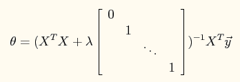
在有规则项的线性回归问题求解中,如果采用梯度下降法,则参数的更新公式类似(其中参数0的公式是一样的,因为规则项中没有惩罚参数0),不同之处在于其它参数的更新公式中的更新不是用本身的参数去减掉后面一串,而是用本身参数乘以(1-alpha*lamda/m)再减掉其它的,当然了这个数在很多情况下和1是相等的,也就很前面的无规则项的梯度下降法类似了。它的normal equation也很前面的类似,大致为inv(X’*X+lamda*A)*X’*y,多了一项,其中A是一个对角矩阵,除了第一个元素为0外,其它元素都为1(在通用规则项下的情形)。这种情况下前面的矩阵一般就是可逆的了,即在样本数量小于特征数量的情况下是可解的。当为logistic回归的情况中(此时的loss函数中含有对数项),如果使用梯度下降法,则参数的更新方程中也和线性回归中的类似,也是要乘以(1-alpha*lamda/m),nomal equation中也是多了一个矩阵,这样同理就解决了不可逆问题。在牛顿法的求解过程中,加了规则项后的一元导向量都随着改变,hession矩阵也要在最后加入lamda/m*A矩阵,其中A和前面的一样。
logistic回归与多充线性回归实际上有很多相同之处,最大的区别就在于他们的因变量不同,其他的基本都差不多,正是因为如此,这两种回归可以归于同一个家族,即广义线性模型(generalized linear model)。这一家族中的模型形式基本上都差不多,不同的就是因变量不同,如果是连续的,就是多重线性回归,如果是二项分布,就是logistic回归,如果是poisson分布,就是poisson回归,如果是负二项分布,就是负二项回归,等等。只要注意区分它们的因变量就可以了。logistic回归的因变量可以是二分类的,也可以是多分类的,但是二分类的更为常用,也更加容易解释。所以实际中最为常用的就是二分类的logistic回归。
参考资料:
http://openclassroom.stanford.edu/MainFolder/CoursePage.php?course=DeepLearning
http://deeplearning.stanford.edu/wiki/index.php/UFLDL_Tutorial
Deep learning:二(linear regression练习)
前言
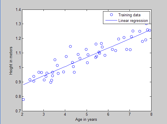
本文是多元线性回归的练习,这里练习的是最简单的二元线性回归,参考斯坦福大学的教学网http://openclassroom.stanford.edu/MainFolder/DocumentPage.php?course=DeepLearning&doc=exercises/ex2/ex2.html。本题给出的是50个数据样本点,其中x为这50个小朋友到的年龄,年龄为2岁到8岁,年龄可有小数形式呈现。Y为这50个小朋友对应的身高,当然也是小数形式表示的。现在的问题是要根据这50个训练样本,估计出3.5岁和7岁时小孩子的身高。通过画出训练样本点的分布凭直觉可以发现这是一个典型的线性回归问题。
matlab函数介绍:
legend:
比如legend('Training data', 'Linear regression'),它表示的是标出图像中各曲线标志所代表的意义,这里图像的第一条曲线(其实是离散的点)表示的是训练样本数据,第二条曲线(其实是一条直线)表示的是回归曲线。
hold on, hold off:
hold on指在前一幅图的情况下打开画纸,允许在上面继续画曲线。hold off指关闭前一副画的画纸。
linspace:
比如linspace(-3, 3, 100)指的是给出-3到3之间的100个数,均匀的选取,即线性的选取。
logspace:
比如logspace(-2, 2, 15),指的是在10^(-2)到10^(2)之间选取15个数,这些数按照指数大小来选取,即指数部分是均匀选取的,但是由于都取了10为底的指数,所以最终是服从指数分布选取的。
实验结果:
训练样本散点和回归曲线预测图:
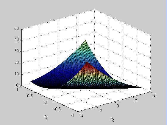
损失函数与参数之间的曲面图:
损失函数的等高线图:
程序代码及注释:
采用normal equations方法求解:
%%方法一
x = load('ex2x.dat');
y = load('ex2y.dat');
plot(x,y,'*')
xlabel('height')
ylabel('age')
x = [ones(size(x),1),x];
w=inv(x'*x)*x'*y
hold on
%plot(x,0.0639*x+0.7502)
plot(x(:,2),0.0639*x(:,2)+0.7502)%更正后的代码
采用gradient descend过程求解:
% Exercise 2 Linear Regression

% Data is roughly based on 2000 CDC growth figures
% for boys
%
% x refers to a boy's age
% y is a boy's height in meters
%

clear all; close all; clc
x = load('ex2x.dat'); y = load('ex2y.dat');

m = length(y); % number of training examples


% Plot the training data
figure; % open a new figure window
plot(x, y, 'o');
ylabel('Height in meters')
xlabel('Age in years')

% Gradient descent
x = [ones(m, 1) x]; % Add a column of ones to x
theta = zeros(size(x(1,:)))'; % initialize fitting parameters
MAX_ITR = 1500;
alpha = 0.07;

for num_iterations = 1:MAX_ITR
    % This is a vectorized version of the
    % gradient descent update formula
    % It's also fine to use the summation formula from the videos

    % Here is the gradient
    grad = (1/m).* x' * ((x * theta) - y);

    % Here is the actual update
    theta = theta - alpha .* grad;

    % Sequential update: The wrong way to do gradient descent
    % grad1 = (1/m).* x(:,1)' * ((x * theta) - y);
    % theta(1) = theta(1) + alpha*grad1;
    % grad2 = (1/m).* x(:,2)' * ((x * theta) - y);
    % theta(2) = theta(2) + alpha*grad2;
end
% print theta to screen
theta

% Plot the linear fit
hold on; % keep previous plot visible
plot(x(:,2), x*theta, '-')
legend('Training data', 'Linear regression')%标出图像中各曲线标志所代表的意义
hold off % don't overlay any more plots on this figure,指关掉前面的那幅图

% Closed form solution for reference
% You will learn about this method in future videos
exact_theta = (x' * x)\x' * y

% Predict values for age 3.5 and 7
predict1 = [1, 3.5] *theta
predict2 = [1, 7] * theta


% Calculate J matrix

% Grid over which we will calculate J
theta0_vals = linspace(-3, 3, 100);
theta1_vals = linspace(-1, 1, 100);

% initialize J_vals to a matrix of 0's
J_vals = zeros(length(theta0_vals), length(theta1_vals));

for i = 1:length(theta0_vals)
      for j = 1:length(theta1_vals)
      t = [theta0_vals(i); theta1_vals(j)];
      J_vals(i,j) = (0.5/m) .* (x * t - y)' * (x * t - y);
    end
end

% Because of the way meshgrids work in the surf command, we need to
% transpose J_vals before calling surf, or else the axes will be flipped
J_vals = J_vals';
% Surface plot
figure;
surf(theta0_vals, theta1_vals, J_vals)
xlabel('\theta_0'); ylabel('\theta_1');

% Contour plot
figure;
% Plot J_vals as 15 contours spaced logarithmically between 0.01 and 100
contour(theta0_vals, theta1_vals, J_vals, logspace(-2, 2, 15))%画出等高线
xlabel('\theta_0'); ylabel('\theta_1');%类似于转义字符,但是最多只能是到参数0~9
参考资料:
http://openclassroom.stanford.edu/MainFolder/DocumentPage.php?course=DeepLearning&doc=exercises/ex2/ex2.html
Deep learning:三(Multivariance Linear Regression练习)
前言:
本文主要是来练习多变量线性回归问题(其实本文也就3个变量),参考资料见网页:http://openclassroom.stanford.edu/MainFolder/DocumentPage.php?course=DeepLearning&doc=exercises/ex3/ex3.html.其实在上一篇博文Deep learning:二(linear regression练习)中已经简单介绍过一元线性回归问题的求解,但是那个时候用梯度下降法求解时,给出的学习率是固定的0.7.而本次实验中学习率需要自己来选择,因此我们应该从小到大(比如从0.001到10)来选择,通过观察损失值与迭代次数之间的函数曲线来决定使用哪个学习速率。当有了学习速率alpha后,则本问问题求解方法和上面的没差别。
本文要解决的问题是给出了47个训练样本,训练样本的y值为房子的价格,x属性有2个,一个是房子的大小,另一个是房子卧室的个数。需要通过这些训练数据来学习系统的函数,从而预测房子大小为1650,且卧室有3个的房子的价格。
实验基础:
dot(A,B):表示的是向量A和向量B的内积。
又线性回归的理论可以知道系统的损失函数如下所示:
其向量表达形式如下:
当使用梯度下降法进行参数的求解时,参数的更新公式如下:
当然它也有自己的向量形式(程序中可以体现)。
实验结果:
测试学习率的结果如下:
由此可知,选用学习率为1时,可以到达很快的收敛速度,因此最终的程序中使用的学习率为1.
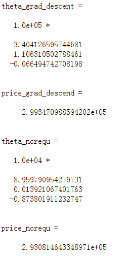
最终使用梯度下降法和公式法的预测结果如下:
可以看出两者的结果是一致的。
实验主要程序及代码:
%% 方法一:梯度下降法
x = load('ex3x.dat');
y = load('ex3y.dat');

x = [ones(size(x,1),1) x];
meanx = mean(x);%求均值
sigmax = std(x);%求标准偏差
x(:,2) = (x(:,2)-meanx(2))./sigmax(2);
x(:,3) = (x(:,3)-meanx(3))./sigmax(3);

figure
itera_num = 100; %尝试的迭代次数
sample_num = size(x,1); %训练样本的次数
alpha = [0.01, 0.03, 0.1, 0.3, 1, 1.3];%因为差不多是选取每个3倍的学习率来测试,所以直接枚举出来
plotstyle = {'b', 'r', 'g', 'k', 'b--', 'r--'};

theta_grad_descent = zeros(size(x(1,:)));
for alpha_i = 1:length(alpha) %尝试看哪个学习速率最好
    theta = zeros(size(x,2),1); %theta的初始值赋值为0
    Jtheta = zeros(itera_num, 1);
    for i = 1:itera_num %计算出某个学习速率alpha下迭代itera_num次数后的参数
        Jtheta(i) = (1/(2*sample_num)).*(x*theta-y)'*(x*theta-y);%Jtheta是个行向量
        grad = (1/sample_num).*x'*(x*theta-y);
        theta = theta - alpha(alpha_i).*grad;
    end
    plot(0:49, Jtheta(1:50),char(plotstyle(alpha_i)),'LineWidth', 2)%此处一定要通过char函数来转换
    hold on

    if(1 == alpha(alpha_i)) %通过实验发现alpha为1时效果最好,则此时的迭代后的theta值为所求的值
        theta_grad_descent = theta
    end
end
legend('0.01','0.03','0.1','0.3','1','1.3');
xlabel('Number of iterations')
ylabel('Cost function')

%下面是预测公式
price_grad_descend = theta_grad_descent'*[1 (1650-meanx(2))/sigmax(2) (3-meanx(3)/sigmax(3))]'


%%方法二:normal equations
x = load('ex3x.dat');
y = load('ex3y.dat');
x = [ones(size(x,1),1) x];

theta_norequ = inv((x'*x))*x'*y
price_norequ = theta_norequ'*[1 1650 3]'
参考资料:
http://openclassroom.stanford.edu/MainFolder/DocumentPage.php?course=DeepLearning&doc=exercises/ex3/ex3.html
Deep learning:四(logistic regression练习)
前言:
本节来练习下logistic regression相关内容,参考的资料为网页:http://openclassroom.stanford.edu/MainFolder/DocumentPage.php?course=DeepLearning&doc=exercises/ex4/ex4.html。这里给出的训练样本的特征为80个学生的两门功课的分数,样本值为对应的同学是否允许被上大学,如果是允许的话则用’1’表示,否则不允许就用’0’表示,这是一个典型的二分类问题。在此问题中,给出的80个样本中正负样本各占40个。而这节采用的是logistic regression来求解,该求解后的结果其实是一个概率值,当然通过与0.5比较就可以变成一个二分类问题了。
实验基础:
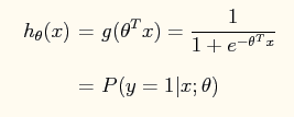
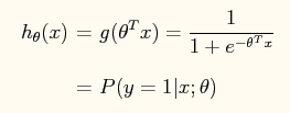
在logistic regression问题中,logistic函数表达式如下:
这样做的好处是可以把输出结果压缩到0~1之间。而在logistic回归问题中的损失函数与线性回归中的损失函数不同,这里定义的为:
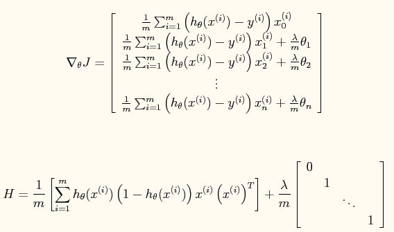
如果采用牛顿法来求解回归方程中的参数,则参数的迭代公式为:
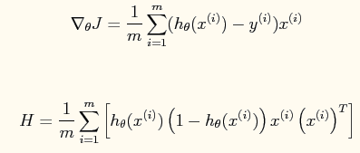
其中一阶导函数和hessian矩阵表达式如下:
当然了,在编程的时候为了避免使用for循环,而应该直接使用这些公式的矢量表达式(具体的见程序内容)。
一些matlab函数:
find:
是找到的一个向量,其结果是find函数括号值为真时的值的下标编号。
inline:
构造一个内嵌的函数,很类似于我们在草稿纸上写的数学推导公式一样。参数一般用单引号弄起来,里面就是函数的表达式,如果有多个参数,则后面用单引号隔开一一说明。比如:g = inline('sin(alpha*x)','x','alpha'),则该二元函数是g(x,alpha) = sin(alpha*x)。
实验结果:
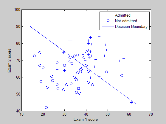
训练样本的分布图以及所学习到的分类界面曲线:
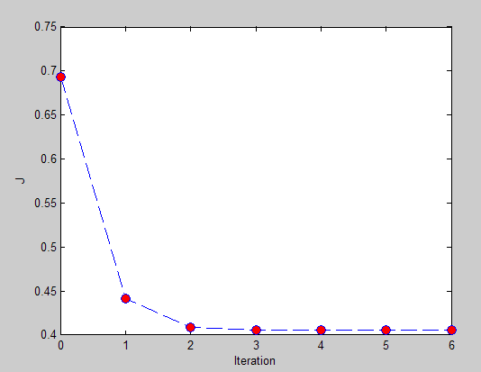
损失函数值和迭代次数之间的曲线:
最终输出的结果:
可以看出当一个小孩的第一门功课为20分,第二门功课为80分时,这个小孩不允许上大学的概率为0.6680,因此如果作为二分类的话,就说明该小孩不会被允许上大学。
实验代码(原网页提供):
% Exercise 4 -- Logistic Regression

clear all; close all; clc

x = load('ex4x.dat');
y = load('ex4y.dat');

[m, n] = size(x);

% Add intercept term to x
x = [ones(m, 1), x];

% Plot the training data
% Use different markers for positives and negatives
figure
pos = find(y); neg = find(y == 0);%find是找到的一个向量,其结果是find函数括号值为真时的值的编号
plot(x(pos, 2), x(pos,3), '+')
hold on
plot(x(neg, 2), x(neg, 3), 'o')
hold on
xlabel('Exam 1 score')
ylabel('Exam 2 score')


% Initialize fitting parameters
theta = zeros(n+1, 1);

% Define the sigmoid function
g = inline('1.0 ./ (1.0 + exp(-z))');

% Newton's method
MAX_ITR = 7;
J = zeros(MAX_ITR, 1);

for i = 1:MAX_ITR
    % Calculate the hypothesis function
    z = x * theta;
    h = g(z);%转换成logistic函数

    % Calculate gradient and hessian.
    % The formulas below are equivalent to the summation formulas
    % given in the lecture videos.
    grad = (1/m).*x' * (h-y);%梯度的矢量表示法
    H = (1/m).*x' * diag(h) * diag(1-h) * x;%hessian矩阵的矢量表示法

    % Calculate J (for testing convergence)
    J(i) =(1/m)*sum(-y.*log(h) - (1-y).*log(1-h));%损失函数的矢量表示法

    theta = theta - H\grad;%是这样子的吗?
end
% Display theta
theta

% Calculate the probability that a student with
% Score 20 on exam 1 and score 80 on exam 2
% will not be admitted
prob = 1 - g([1, 20, 80]*theta)

%画出分界面
% Plot Newton's method result
% Only need 2 points to define a line, so choose two endpoints
plot_x = [min(x(:,2))-2,  max(x(:,2))+2];
% Calculate the decision boundary line
plot_y = (-1./theta(3)).*(theta(2).*plot_x +theta(1));
plot(plot_x, plot_y)
legend('Admitted', 'Not admitted', 'Decision Boundary')
hold off

% Plot J
figure
plot(0:MAX_ITR-1, J, 'o--', 'MarkerFaceColor', 'r', 'MarkerSize', 8)
xlabel('Iteration'); ylabel('J')
% Display J
J
参考资料:
http://openclassroom.stanford.edu/MainFolder/DocumentPage.php?course=DeepLearning&doc=exercises/ex4/ex4.html
Deep learning:五(regularized线性回归练习)
前言:
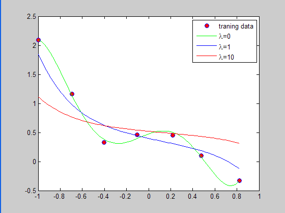
本节主要是练习regularization项的使用原则。因为在机器学习的一些模型中,如果模型的参数太多,而训练样本又太少的话,这样训练出来的模型很容易产生过拟合现象。因此在模型的损失函数中,需要对模型的参数进行“惩罚”,这样的话这些参数就不会太大,而越小的参数说明模型越简单,越简单的模型则越不容易产生过拟合现象。本文参考的资料参考网页:http://openclassroom.stanford.edu/MainFolder/DocumentPage.php?course=DeepLearning&doc=exercises/ex5/ex5.html。主要是给定7个训练样本点,需要用这7个点来模拟一个5阶多项式。主要测试的是不同的regularization参数对最终学习到的曲线的影响。
实验基础:
此时的模型表达式如下所示:
模型中包含了规则项的损失函数如下:
模型的normal equation求解为:
程序中主要测试lambda=0,1,10这3个参数对最终结果的影响。
一些matlab函数:
plot:
主要是将plot绘曲线的一些性质。比如说:plot(x,y,'o','MarkerEdgeColor','b','MarkerFaceColor','r')这里是绘制x-y的点图,每个点都是圆圈表示,圆圈的边缘用蓝色表示,圆圈里面填充的是红色。由此可知’MarkerEdgeColor’和’MarkerFaceColor’的含义了。
diag:
diag使用来产生对角矩阵的,它是用一个列向量来生成对角矩阵的,所以其参数应该是个列向量,比如说如果想产生3*3的对角矩阵,则可以是diag(ones(3,1)).
legend:
注意转义字符的使用,比如说legned(‘\lambda_0’),说明标注的是lamda0.
实验结果:
样本点的分布和最终学习到的曲线如下所示:
可以看出,当lambda=1时,模型最好,不容易产生过拟合现象,且有对原始数据有一定的模拟。
实验主要代码:
clc,clear
%加载数据
x = load('ex5Linx.dat');
y = load('ex5Liny.dat');

%显示原始数据
plot(x,y,'o','MarkerEdgeColor','b','MarkerFaceColor','r')

%将特征值变成训练样本矩阵
x = [ones(length(x),1) x x.^2 x.^3 x.^4 x.^5];
[m n] = size(x);
n = n -1;

%计算参数sidta,并且绘制出拟合曲线
rm = diag([0;ones(n,1)]);%lamda后面的矩阵
lamda = [0 1 10]';
colortype = {'g','b','r'};
sida = zeros(n+1,3);
xrange = linspace(min(x(:,2)),max(x(:,2)))';
hold on;
for i = 1:3
    sida(:,i) = inv(x'*x+lamda(i).*rm)*x'*y;%计算参数sida
    norm_sida = norm(sida)
    yrange = [ones(size(xrange)) xrange xrange.^2 xrange.^3,...
        xrange.^4 xrange.^5]*sida(:,i);
    plot(xrange',yrange,char(colortype(i)))
    hold on
end
legend('traning data', '\lambda=0', '\lambda=1','\lambda=10')%注意转义字符的使用方法
hold off
参考资料:
http://openclassroom.stanford.edu/MainFolder/DocumentPage.php?course=DeepLearning&doc=exercises/ex5/ex5.html
Deep learning:六(regularized logistic回归练习)
前言:
在上一讲Deep learning:五(regularized线性回归练习)中已经介绍了regularization项在线性回归问题中的应用,这节主要是练习regularization项在logistic回归中的应用,并使用牛顿法来求解模型的参数。参考的网页资料为:http://openclassroom.stanford.edu/MainFolder/DocumentPage.php?course=DeepLearning&doc=exercises/ex5/ex5.html。要解决的问题是,给出了具有2个特征的一堆训练数据集,从该数据的分布可以看出它们并不是非常线性可分的,因此很有必要用更高阶的特征来模拟。例如本程序中个就用到了特征值的6次方来求解。
实验基础:
contour:
该函数是绘制轮廓线的,比如程序中的contour(u, v, z, [0, 0], 'LineWidth', 2),指的是在二维平面U-V中绘制曲面z的轮廓,z的值为0,轮廓线宽为2。注意此时的z对应的范围应该与U和V所表达的范围相同。
在logistic回归中,其表达式为:
在此问题中,将特征x映射到一个28维的空间中,其x向量映射后为:
此时加入了规则项后的系统的损失函数为:
对应的牛顿法参数更新方程为:
其中:
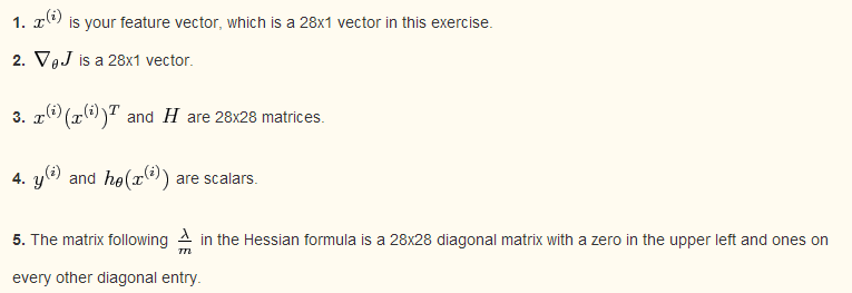
公式中的一些宏观说明(直接截的原网页):
实验结果:
原训练数据点的分布情况:
当lambda=0时所求得的分界曲面:
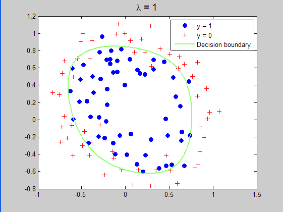
当lambda=1时所求得的分界曲面:
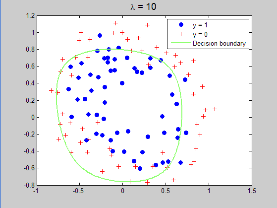
当lambda=10时所求得的分界曲面:
实验程序代码:
%载入数据
clc,clear,close all;
x = load('ex5Logx.dat');
y = load('ex5Logy.dat');

%画出数据的分布图
plot(x(find(y),1),x(find(y),2),'o','MarkerFaceColor','b')
hold on;
plot(x(find(y==0),1),x(find(y==0),2),'r+')
legend('y=1','y=0')

% Add polynomial features to x by
% calling the feature mapping function
% provided in separate m-file
x = map_feature(x(:,1), x(:,2));

[m, n] = size(x);

% Initialize fitting parameters
theta = zeros(n, 1);

% Define the sigmoid function
g = inline('1.0 ./ (1.0 + exp(-z))');

% setup for Newton's method
MAX_ITR = 15;
J = zeros(MAX_ITR, 1);

% Lambda is the regularization parameter
lambda = 1;%lambda=0,1,10,修改这个地方,运行3次可以得到3种结果。

% Newton's Method
for i = 1:MAX_ITR
    % Calculate the hypothesis function
    z = x * theta;
    h = g(z);

    % Calculate J (for testing convergence)
    J(i) =(1/m)*sum(-y.*log(h) - (1-y).*log(1-h))+ ...
    (lambda/(2*m))*norm(theta([2:end]))^2;

    % Calculate gradient and hessian.
    G = (lambda/m).*theta; G(1) = 0; % extra term for gradient
    L = (lambda/m).*eye(n); L(1) = 0;% extra term for Hessian
    grad = ((1/m).*x' * (h-y)) + G;
    H = ((1/m).*x' * diag(h) * diag(1-h) * x) + L;

    % Here is the actual update
    theta = theta - H\grad;

end
% Show J to determine if algorithm has converged
J
% display the norm of our parameters
norm_theta = norm(theta)

% Plot the results
% We will evaluate theta*x over a
% grid of features and plot the contour
% where theta*x equals zero

% Here is the grid range
u = linspace(-1, 1.5, 200);
v = linspace(-1, 1.5, 200);

z = zeros(length(u), length(v));
% Evaluate z = theta*x over the grid
for i = 1:length(u)
    for j = 1:length(v)
        z(i,j) = map_feature(u(i), v(j))*theta;%这里绘制的并不是损失函数与迭代次数之间的曲线,而是线性变换后的值
    end
end
z = z'; % important to transpose z before calling contour

% Plot z = 0
% Notice you need to specify the range [0, 0]
contour(u, v, z, [0, 0], 'LineWidth', 2)%在z上画出为0值时的界面,因为为0时刚好概率为0.5,符合要求
legend('y = 1', 'y = 0', 'Decision boundary')
title(sprintf('\\lambda = %g', lambda), 'FontSize', 14)


hold off

% Uncomment to plot J
% figure
% plot(0:MAX_ITR-1, J, 'o--', 'MarkerFaceColor', 'r', 'MarkerSize', 8)
% xlabel('Iteration'); ylabel('J')
参考文献:
Deep learning:五(regularized线性回归练习)
http://openclassroom.stanford.edu/MainFolder/DocumentPage.php?course=DeepLearning&doc=exercises/ex5/ex5.html
Deep learning:七(基础知识_2)
前面的文章已经介绍过了2种经典的机器学习算法:线性回归和logistic回归,并且在后面的练习中也能够感觉到这2种方法在一些问题的求解中能够取得很好的效果。现在开始来看看另一种机器学习算法——神经网络。线性回归或者logistic回归问题理论上不是可以解决所有的回归和分类问题么,那么为什么还有其它各种各样的机器学习算法呢?比如这里马上要讲的神经网络算法。其实原因很简单,在前面的一系列博文练习中可以发现,那些样本点的输入特征维数都非常小(比如说2到3维),在使用logistic回归求解时,需要把原始样本特征重新映射到高维空间中,本来是3维的如果映射到最高指数为6的空间中,结果就变成了28维了。但是一般现实生活中的数据特征非常大,比如一张小的可怜的灰度图片50*50,本身就只有2500个特征,如果要采用logistic回归来做目标检测的话,则有可能达到上百万的特征了。这样不仅计算量复杂,而且因为特征维数过大容易是学习到的函数产生过拟合现象。总的来说,只有线性回归和logistic回归在现实生活中是远远不够的,因此,神经网络由于它特有的优势就慢慢被研究了。
神经网络模型的表达结构是比较清晰的,输入值和对应的权重相乘然后相加最终加上个偏移值就是输出了。只是数学公式比较繁琐,容易弄错。假设第j层网络有Sj个节点,而第j+1层网络有S(j+1)个节点,则第j层的参数应该是个矩阵,矩阵大小为S(j+1)*(Sj+1),当然了,此时是因为那个权值为1的那个网络节点没有算进去。很显然,为了方便公式的表达,神经网络中经常使用矢量化的数学公式。为什么神经网络最有学习功能呢?首先从生物上来讲,它模拟了人的大脑的功能,而人的大脑就有很强大的学习机制。其次从神经网络的模型中也可以看出,如果我们只看输出层已经和输出层相连的最后一层可以发现,它其实就是一个简单的线性回归方程(如果使输出在0~1之间,则是logistic回归方程),也就是说前面那么多的网络只是自己学习到了一些新的特征,而这些新的特征是很适合作为问题求解的特征的。因此,说白了,神经网络是为了学习到更适合问题求解的一些特征。
表面上看,神经网络的前一层和当前层是直接连接的,前一层的输出值的线性组合构成了当前层的输出,这样即使是有很多层的神经网络,不也只能学习到输入特征的线性组合么?那为什么说神经网络可以学习任意的非线性函数呢?其实是刚才我犯了一个本质错误,因为前一层输出的线性组合并不直接是本层的输出,而是一般还通过一个函数复合,比如说最常见的函数logistic函数(其它的函数比如双曲正切函数也是很常用的),要不然可就真是只能学习到线性的特征了。神经网络的功能是比较强大的,比如说单层的神经网络可以学习到”and”,”or”,,”not”以及非或门等,两层的神经网络可以学习到”xor”门(通过与门和非或门构成的一个或门合成),3层的神经网络是可以学习到任意函数的(不包括输入输出层)等,这些在神经网络的发展过程中有不少有趣的故事。当然了,神经网络也是很容易用来扩展到多分类问题的,如果是n分类问题,则只需在设计的网络的输出层设置n个节点即可。这样如果系统是可分的话则总有一个学习到的网络能够使输入的特征最终在n个输出节点中只有一个为1,这就达到了多分类的目的。
神经网络的损失函数其实是很容易确定的,这里以多分类的神经网络为例。当然了,这里谈到损失函数是在有监督学习理论框架下的,因为只有这样才能够知道损失了多少(最近有发展到无监督学习框架中也是可以计算损失函数的,比如说AutoEncoder等)。假设网络中各个参数均已学到,那么对于每个输入样本,就能够得出一个输出值了,这个输出值和输入样本标注的输出值做比较就能够得到一个损失项。由于多分类中的输出值是一个多维的向量,所以计算它的损失时需要每一维都求(既然是多分类问题,那么训练样本所标注的值也应该为多维的,至少可以转换成多维的)。这样的话,神经网络的损失函数表达式与前面的logistic回归中损失函数表达式很类似,很容易理解。
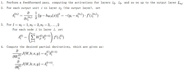
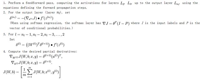
有了损失函数的表达式,我们就可以用梯度下降法或者牛顿法来求网络的参数了,不管是哪种方法,都需要计算出损失函数对某个参数的偏导数,这样我们的工作重点就在求损失函数对各个参数的偏导数了,求该偏导数中最著名的算法就是BP算法,也叫做反向传播算法。在使用BP算法求偏导数时,可以证明损失函数对第l层的某个参数的偏导与第l层中该节点的误差,以及该参数对应前一层网络编号在本层的输出(即l层)的输出值有关,那么此时的工作就转换成了每一层网络的每一个节点的误差的求法了(当然了,输入层是不用计算误差的)。而又可通过理论证明,每个节点的误差是可以通过下一层网络的所以节点反向传播计算得到(这也是反向传播算法名字的来源)。总结一下,当有多个训练样本时,每次输入一个样本,然后求出每个节点的输出值,接着通过输入样本的样本值反向求出每个节点的误差,这样损失函数对每个节点的误差可以通过该节点的输出值已经误差来累加得到,当所有的样本都经过同样的处理后,其最终的累加值就是损失函数对应位置参数的偏导数了。BP算法的理论来源是一个节点的误差是由前面简单的误差传递过来的,传递系数就是网络的系数。
一般情况下,使用梯度下降法解决神经网络问题时是很容易出错,因为求解损失函数对参数的偏导数过程有不少矩阵,在程序中容易弄错,如果损失函数或者损失函数的偏导数都求错了的话,那么后面的迭代过程就更加错了,导致不会收敛,所以很有必要检查一下偏导数是否正确。Andrew Ng在课程中告诉大家使用gradient checking的方法来检测,即当求出了损失函数的偏导数后,取一个参数值,计算出该参数值处的偏导数值,然后在该参数值附近取2个参数点,利用损失函数在这个两个点值的差除以这2个点的距离(其实如果这2个点足够靠近的话,这个结果就是导数的定义了),比较这两次计算出的结果是否相等,如果接近相等的话,则说明很大程度上,这个偏导数没有计算出错,后面的工作也就可以放心的进行了,这时候一定要记住不要再运行gradient checking,因为在运行gradient checking时会使用BP进行每层的误差等计算,这样很耗时(但是我感觉即使不计算gradient checking,不也要使用BP算法进行反向计算么?)。
在进行网络训练时,千万不要将参数的初始值设置成一样的,因为这样学习的每一层的参数最终都是一样的,也就是说学习到的隐含特征是一样的,那么就多余了,且效果不好。因此明智的做法是对这些参数的初始化应该随机,且一般是满足均值为0,且在0左右附近的随机。
如果采用同样的算法求解网络的参数的话(比如说都是用BP算法),那么网络的性能就取决于网络的结构(即隐含层的个数以及每个隐含层神经元的个数),一般默认的结构是:只取一个隐含层,如果需要取多个隐含层的话就将每个隐含层神经元的个数设置为相同,当然了隐含层神经元的个数越多则效果会越好。
Deep learning:八(Sparse Autoencoder)
前言:
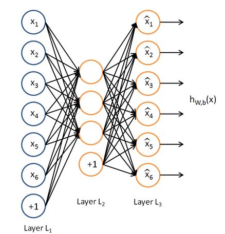
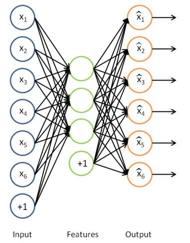
这节课来学习下Deep learning领域比较出名的一类算法——sparse autoencoder,即稀疏模式的自动编码。我们知道,deep learning也叫做unsupervised learning,所以这里的sparse autoencoder也应是无监督的。按照前面的博文:Deep learning:一(基础知识_1),Deep learning:七(基础知识_2)所讲,如果是有监督的学习的话,在神经网络中,我们只需要确定神经网络的结构就可以求出损失函数的表达式了(当然,该表达式需对网络的参数进行”惩罚”,以便使每个参数不要太大),同时也能够求出损失函数偏导函数的表达式,然后利用优化算法求出网络最优的参数。应该清楚的是,损失函数的表达式中,需要用到有标注值的样本。那么这里的sparse autoencoder为什么能够无监督学习呢?难道它的损失函数的表达式中不需要标注的样本值(即通常所说的y值)么?其实在稀疏编码中”标注值”也是需要的,只不过它的输出理论值是本身输入的特征值x,其实这里的标注值y=x。这样做的好处是,网络的隐含层能够很好的代替输入的特征,因为它能够比较准确的还原出那些输入特征值。Sparse autoencoder的一个网络结构图如下所示:
损失函数的求法:
无稀疏约束时网络的损失函数表达式如下:
稀疏编码是对网络的隐含层的输出有了约束,即隐含层节点输出的平均值应尽量为0,这样的话,大部分的隐含层节点都处于非activite状态。因此,此时的sparse autoencoder损失函数表达式为:
后面那项为KL距离,其表达式如下:
隐含层节点输出平均值求法如下:
其中的参数一般取很小,比如说0.05,也就是小概率发生事件的概率。这说明要求隐含层的每一个节点的输出均值接近0.05(其实就是接近0,因为网络中activite函数为sigmoid函数),这样就达到稀疏的目的了。KL距离在这里表示的是两个向量之间的差异值。从约束函数表达式中可以看出,差异越大则”惩罚越大”,因此最终的隐含层节点的输出会接近0.05。
损失函数的偏导数的求法:
如果不加入稀疏规则,则正常情况下由损失函数求损失函数偏导数的过程如下:
而加入了稀疏性后,神经元节点的误差表达式由公式:
变成公式:
梯度下降法求解:
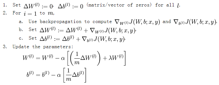
有了损失函数及其偏导数后就可以采用梯度下降法来求网络最优化的参数了,整个流程如下所示:
从上面的公式可以看出,损失函数的偏导其实是个累加过程,每来一个样本数据就累加一次。这是因为损失函数本身就是由每个训练样本的损失叠加而成的,而按照加法的求导法则,损失函数的偏导也应该是由各个训练样本所损失的偏导叠加而成。从这里可以看出,训练样本输入网络的顺序并不重要,因为每个训练样本所进行的操作是等价的,后面样本的输入所产生的结果并不依靠前一次输入结果(只是简单的累加而已,而这里的累加是顺序无关的)。
参考资料:
Deep learning:一(基础知识_1)
Deep learning:七(基础知识_2)
http://deeplearning.stanford.edu/wiki/index.php/Autoencoders_and_Sparsity
Deep learning:九(Sparse Autoencoder练习)
前言:
现在来进入sparse autoencoder的一个实例练习,参考Ng的网页教程:Exercise:Sparse Autoencoder。这个例子所要实现的内容大概如下:从给定的很多张自然图片中截取出大小为8*8的小patches图片共10000张,现在需要用sparse autoencoder的方法训练出一个隐含层网络所学习到的特征。该网络共有3层,输入层是64个节点,隐含层是25个节点,输出层当然也是64个节点了。
实验基础:
其实实现该功能的主要步骤还是需要计算出网络的损失函数以及其偏导数,具体的公式可以参考前面的博文Deep learning:八(Sparse Autoencoder)。下面用简单的语言大概介绍下这个步骤,方便大家理清算法的流程。
1. 计算出网络每个节点的输入值(即程序中的z值)和输出值(即程序中的a值,a是z的sigmoid函数值)。
2. 利用z值和a值计算出网络每个节点的误差值(即程序中的delta值)。
3. 这样可以利用上面计算出的每个节点的a,z,delta来表达出系统的损失函数以及损失函数的偏导数了,当然这些都是一些数学推导,其公式就是前面的博文Deep learning:八(Sparse Autoencoder)了。
其实步骤1是前向进行的,也就是说按照输入层——》隐含层——》输出层的方向进行计算。而步骤2是方向进行的(这也是该算法叫做BP算法的来源),即每个节点的误差值是按照输出层——》隐含层——》输入层方向进行的。
一些malab函数:
bsxfun:
C=bsxfun(fun,A,B)表达的是两个数组A和B间元素的二值操作,fun是函数句柄或者m文件,或者是内嵌的函数。在实际使用过程中fun有很多选择比如说加,减等,前面需要使用符号’@’.一般情况下A和B需要尺寸大小相同,如果不相同的话,则只能有一个维度不同,同时A和B中在该维度处必须有一个的维度为1。比如说bsxfun(@minus, A, mean(A)),其中A和mean(A)的大小是不同的,这里的意思需要先将mean(A)扩充到和A大小相同,然后用A的每个元素减去扩充后的mean(A)对应元素的值。
rand:
生成均匀分布的伪随机数。分布在(0~1)之间
主要语法:rand(m,n)生成m行n列的均匀分布的伪随机数
rand(m,n,'double')生成指定精度的均匀分布的伪随机数,参数还可以是'single'
rand(RandStream,m,n)利用指定的RandStream(我理解为随机种子)生成伪随机数
randn:
生成标准正态分布的伪随机数(均值为0,方差为1)。主要语法:和上面一样
randi:
生成均匀分布的伪随机整数
主要语法:randi(iMax)在闭区间(0,iMax)生成均匀分布的伪随机整数
randi(iMax,m,n)在闭区间(0,iMax)生成mXn型随机矩阵
r = randi([iMin,iMax],m,n)在闭区间(iMin,iMax)生成mXn型随机矩阵
exist:
测试参数是否存在,比如说exist('opt_normalize', 'var')表示检测变量opt_normalize是否存在,其中的’var’表示变量的意思。
colormap:
设置当前常见的颜色值表。
floor:
floor(A):取不大于A的最大整数。
ceil:
ceil(A):取不小于A的最小整数。
imagesc:
imagesc和image类似,可以用于显示图像。比如imagesc(array,'EraseMode','none',[-1 1]),这里的意思是将array中的数据线性映射到[-1,1]之间,然后使用当前设置的颜色表进行显示。此时的[-1,1]充满了整个颜色表。背景擦除模式设置为node,表示不擦除背景。
repmat:
该函数是扩展一个矩阵并把原来矩阵中的数据复制进去。比如说B = repmat(A,m,n),就是创建一个矩阵B,B中复制了共m*n个A矩阵,因此B矩阵的大小为[size(A,1)*m size(A,2)*m]。
使用函数句柄的作用:
不使用函数句柄的情况下,对函数多次调用,每次都要为该函数进行全面的路径搜索,直接影响计算速度,借助句柄可以完全避免这种时间损耗。也就是直接指定了函数的指针。函数句柄就像一个函数的名字,有点类似于C++程序中的引用。
实验流程:
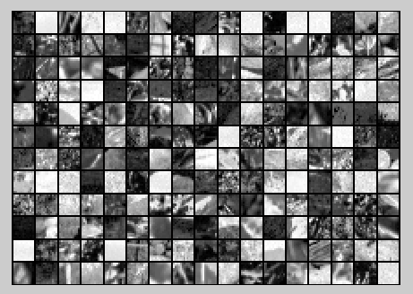
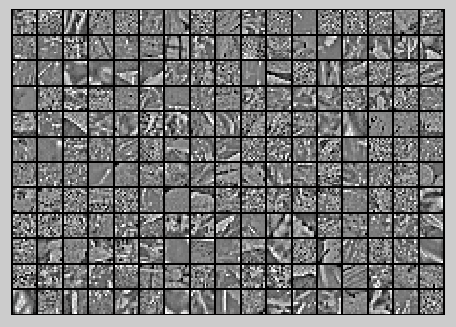
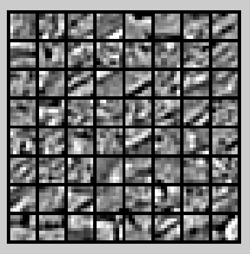
首先运行主程序train.m中的步骤1,即随机采样出10000个小的patch,并且显示出其中的204个patch图像,图像显示如下所示:
然后运行train.m中的步骤2和步骤3,进行损失函数和梯度函数的计算并验证。进行gradient checking的时间可能会太长,我这里大概用了1个半小时以上(反正1个多小时还没checking完,所以去睡觉了),当用gradient checking时,发现误差只有6.5101e-11,远小于1e-9,所以说明前面的损失函数和偏导函数程序是对的。后面就可以接着用优化算法来求参数了,本程序给的是优化算法是L-BFGS。经过几分钟的优化,就出结果了。
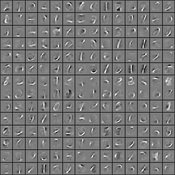
最后的W1的权值如下所示:
实验代码:
train.m:
%% CS294A/CS294W Programming Assignment Starter Code

%  Instructions
%  ------------
%
%  This file contains code that helps you get started on the
%  programming assignment. You will need to complete the code in sampleIMAGES.m,
%  sparseAutoencoderCost.m and computeNumericalGradient.m.
%  For the purpose of completing the assignment, you do not need to
%  change the code in this file.
%
%%======================================================================
%% STEP 0: Here we provide the relevant parameters values that will
%  allow your sparse autoencoder to get good filters; you do not need to
%  change the parameters below.

visibleSize = 8*8;   % number of input units
hiddenSize = 25;     % number of hidden units
sparsityParam = 0.01;   % desired average activation of the hidden units.
                     % (This was denoted by the Greek alphabet rho, which looks like a lower-case "p",
             %  in the lecture notes).
lambda = 0.0001;     % weight decay parameter
beta = 3;            % weight of sparsity penalty term

%%======================================================================
%% STEP 1: Implement sampleIMAGES
%
%  After implementing sampleIMAGES, the display_network command should
%  display a random sample of 200 patches from the dataset

patches = sampleIMAGES;
display_network(patches(:,randi(size(patches,2),204,1)),8);%randi(size(patches,2),204,1)
                                                           %为产生一个204维的列向量,每一维的值为0~10000
                                                           %中的随机数,说明是随机取204个patch来显示


%  Obtain random parameters theta
theta = initializeParameters(hiddenSize, visibleSize);

%%======================================================================
%% STEP 2: Implement sparseAutoencoderCost
%
%  You can implement all of the components (squared error cost, weight decay term,
%  sparsity penalty) in the cost function at once, but it may be easier to do
%  it step-by-step and run gradient checking (see STEP 3) after each step.  We
%  suggest implementing the sparseAutoencoderCost function using the following steps:
%
%  (a) Implement forward propagation in your neural network, and implement the
%      squared error term of the cost function.  Implement backpropagation to
%      compute the derivatives.   Then (using lambda=beta=0), run Gradient Checking
%      to verify that the calculations corresponding to the squared error cost
%      term are correct.
%
%  (b) Add in the weight decay term (in both the cost function and the derivative
%      calculations), then re-run Gradient Checking to verify correctness.
%
%  (c) Add in the sparsity penalty term, then re-run Gradient Checking to
%      verify correctness.
%
%  Feel free to change the training settings when debugging your
%  code.  (For example, reducing the training set size or
%  number of hidden units may make your code run faster; and setting beta
%  and/or lambda to zero may be helpful for debugging.)  However, in your
%  final submission of the visualized weights, please use parameters we
%  gave in Step 0 above.

[cost, grad] = sparseAutoencoderCost(theta, visibleSize, hiddenSize, lambda, ...
                                     sparsityParam, beta, patches);

%%======================================================================
%% STEP 3: Gradient Checking
%
% Hint: If you are debugging your code, performing gradient checking on smaller models
% and smaller training sets (e.g., using only 10 training examples and 1-2 hidden
% units) may speed things up.

% First, lets make sure your numerical gradient computation is correct for a
% simple function.  After you have implemented computeNumericalGradient.m,
% run the following:
checkNumericalGradient();

% Now we can use it to check your cost function and derivative calculations
% for the sparse autoencoder.
numgrad = computeNumericalGradient( @(x) sparseAutoencoderCost(x, visibleSize, ...
                                                  hiddenSize, lambda, ...
                                                  sparsityParam, beta, ...
                                                  patches), theta);

% Use this to visually compare the gradients side by side
%disp([numgrad grad]);

% Compare numerically computed gradients with the ones obtained from backpropagation
diff = norm(numgrad-grad)/norm(numgrad+grad);
disp(diff); % Should be small. In our implementation, these values are
            % usually less than 1e-9.

            % When you got this working, Congratulations!!!

%%======================================================================
%% STEP 4: After verifying that your implementation of
%  sparseAutoencoderCost is correct, You can start training your sparse
%  autoencoder with minFunc (L-BFGS).

%  Randomly initialize the parameters
theta = initializeParameters(hiddenSize, visibleSize);

%  Use minFunc to minimize the function
addpath minFunc/
options.Method = 'lbfgs'; % Here, we use L-BFGS to optimize our cost
                          % function. Generally, for minFunc to work, you
                          % need a function pointer with two outputs: the
                          % function value and the gradient. In our problem,
                          % sparseAutoencoderCost.m satisfies this.
options.maxIter = 400;      % Maximum number of iterations of L-BFGS to run
options.display = 'on';


[opttheta, cost] = minFunc( @(p) sparseAutoencoderCost(p, ...
                                   visibleSize, hiddenSize, ...
                                   lambda, sparsityParam, ...
                                   beta, patches), ...
                              theta, options);

%%======================================================================
%% STEP 5: Visualization

W1 = reshape(opttheta(1:hiddenSize*visibleSize), hiddenSize, visibleSize);
figure;
display_network(W1', 12);

print -djpeg weights.jpg   % save the visualization to a file
sampleIMAGES.m:
function patches = sampleIMAGES()
% sampleIMAGES
% Returns 10000 patches for training

load IMAGES;    % load images from disk

patchsize = 8;  % we'll use 8x8 patches
numpatches = 10000;

% Initialize patches with zeros.  Your code will fill in this matrix--one
% column per patch, 10000 columns.
patches = zeros(patchsize*patchsize, numpatches);

%% ---------- YOUR CODE HERE --------------------------------------
%  Instructions: Fill in the variable called "patches" using data
%  from IMAGES.
%
%  IMAGES is a 3D array containing 10 images
%  For instance, IMAGES(:,:,6) is a 512x512 array containing the 6th image,
%  and you can type "imagesc(IMAGES(:,:,6)), colormap gray;" to visualize
%  it. (The contrast on these images look a bit off because they have
%  been preprocessed using using "whitening."  See the lecture notes for
%  more details.) As a second example, IMAGES(21:30,21:30,1) is an image
%  patch corresponding to the pixels in the block (21,21) to (30,30) of
%  Image 1
for imageNum = 1:10%在每张图片中随机选取1000个patch,共10000个patch
    [rowNum colNum] = size(IMAGES(:,:,imageNum));
    for patchNum = 1:1000%实现每张图片选取1000个patch
        xPos = randi([1,rowNum-patchsize+1]);
        yPos = randi([1, colNum-patchsize+1]);
        patches(:,(imageNum-1)*1000+patchNum) = reshape(IMAGES(xPos:xPos+7,yPos:yPos+7,...
                                                        imageNum),64,1);
    end
end


%% ---------------------------------------------------------------
% For the autoencoder to work well we need to normalize the data
% Specifically, since the output of the network is bounded between [0,1]
% (due to the sigmoid activation function), we have to make sure
% the range of pixel values is also bounded between [0,1]
patches = normalizeData(patches);

end


%% ---------------------------------------------------------------
function patches = normalizeData(patches)

% Squash data to [0.1, 0.9] since we use sigmoid as the activation
% function in the output layer

% Remove DC (mean of images).
patches = bsxfun(@minus, patches, mean(patches));

% Truncate to +/-3 standard deviations and scale to -1 to 1
pstd = 3 * std(patches(:));
patches = max(min(patches, pstd), -pstd) / pstd;%因为根据3sigma法则,95%以上的数据都在该区域内
                                                % 这里转换后将数据变到了-1到1之间

% Rescale from [-1,1] to [0.1,0.9]
patches = (patches + 1) * 0.4 + 0.1;

end
initializeParameters.m:
function theta = initializeParameters(hiddenSize, visibleSize)

%% Initialize parameters randomly based on layer sizes.
r  = sqrt(6) / sqrt(hiddenSize+visibleSize+1);   % we'll choose weights uniformly from the interval [-r, r]
W1 = rand(hiddenSize, visibleSize) * 2 * r - r;
W2 = rand(visibleSize, hiddenSize) * 2 * r - r;

b1 = zeros(hiddenSize, 1);
b2 = zeros(visibleSize, 1);

% Convert weights and bias gradients to the vector form.
% This step will "unroll" (flatten and concatenate together) all
% your parameters into a vector, which can then be used with minFunc.
theta = [W1(:) ; W2(:) ; b1(:) ; b2(:)];

end
sparseAutoencoderCost.m:
function [cost,grad] = sparseAutoencoderCost(theta, visibleSize, hiddenSize, ...
                                             lambda, sparsityParam, beta, data)

% visibleSize: the number of input units (probably 64)
% hiddenSize: the number of hidden units (probably 25)
% lambda: weight decay parameter
% sparsityParam: The desired average activation for the hidden units (denoted in the lecture
%                           notes by the greek alphabet rho, which looks like a lower-case "p").
% beta: weight of sparsity penalty term
% data: Our 64x10000 matrix containing the training data.  So, data(:,i) is the i-th training example.

% The input theta is a vector (because minFunc expects the parameters to be a vector).
% We first convert theta to the (W1, W2, b1, b2) matrix/vector format, so that this
% follows the notation convention of the lecture notes.

%将长向量转换成每一层的权值矩阵和偏置向量值
W1 = reshape(theta(1:hiddenSize*visibleSize), hiddenSize, visibleSize);
W2 = reshape(theta(hiddenSize*visibleSize+1:2*hiddenSize*visibleSize), visibleSize, hiddenSize);
b1 = theta(2*hiddenSize*visibleSize+1:2*hiddenSize*visibleSize+hiddenSize);
b2 = theta(2*hiddenSize*visibleSize+hiddenSize+1:end);

% Cost and gradient variables (your code needs to compute these values).
% Here, we initialize them to zeros.
cost = 0;
W1grad = zeros(size(W1));
W2grad = zeros(size(W2));
b1grad = zeros(size(b1));
b2grad = zeros(size(b2));

%% ---------- YOUR CODE HERE --------------------------------------
%  Instructions: Compute the cost/optimization objective J_sparse(W,b) for the Sparse Autoencoder,
%                and the corresponding gradients W1grad, W2grad, b1grad, b2grad.
%
% W1grad, W2grad, b1grad and b2grad should be computed using backpropagation.
% Note that W1grad has the same dimensions as W1, b1grad has the same dimensions
% as b1, etc.  Your code should set W1grad to be the partial derivative of J_sparse(W,b) with
% respect to W1.  I.e., W1grad(i,j) should be the partial derivative of J_sparse(W,b)
% with respect to the input parameter W1(i,j).  Thus, W1grad should be equal to the term
% [(1/m) \Delta W^{(1)} + \lambda W^{(1)}] in the last block of pseudo-code in Section 2.2
% of the lecture notes (and similarly for W2grad, b1grad, b2grad).
%
% Stated differently, if we were using batch gradient descent to optimize the parameters,
% the gradient descent update to W1 would be W1 := W1 - alpha * W1grad, and similarly for W2, b1, b2.
%

Jcost = 0;%直接误差
Jweight = 0;%权值惩罚
Jsparse = 0;%稀疏性惩罚
[n m] = size(data);%m为样本的个数,n为样本的特征数

%前向算法计算各神经网络节点的线性组合值和active值
z2 = W1*data+repmat(b1,1,m);%注意这里一定要将b1向量复制扩展成m列的矩阵
a2 = sigmoid(z2);
z3 = W2*a2+repmat(b2,1,m);
a3 = sigmoid(z3);

% 计算预测产生的误差
Jcost = (0.5/m)*sum(sum((a3-data).^2));

%计算权值惩罚项
Jweight = (1/2)*(sum(sum(W1.^2))+sum(sum(W2.^2)));

%计算稀释性规则项
rho = (1/m).*sum(a2,2);%求出第一个隐含层的平均值向量
Jsparse = sum(sparsityParam.*log(sparsityParam./rho)+ ...
        (1-sparsityParam).*log((1-sparsityParam)./(1-rho)));

%损失函数的总表达式
cost = Jcost+lambda*Jweight+beta*Jsparse;

%反向算法求出每个节点的误差值
d3 = -(data-a3).*sigmoidInv(z3);
sterm = beta*(-sparsityParam./rho+(1-sparsityParam)./(1-rho));%因为加入了稀疏规则项,所以
                                                             %计算偏导时需要引入该项
d2 = (W2'*d3+repmat(sterm,1,m)).*sigmoidInv(z2);

%计算W1grad
W1grad = W1grad+d2*data';
W1grad = (1/m)*W1grad+lambda*W1;

%计算W2grad
W2grad = W2grad+d3*a2';
W2grad = (1/m).*W2grad+lambda*W2;

%计算b1grad
b1grad = b1grad+sum(d2,2);
b1grad = (1/m)*b1grad;%注意b的偏导是一个向量,所以这里应该把每一行的值累加起来

%计算b2grad
b2grad = b2grad+sum(d3,2);
b2grad = (1/m)*b2grad;


% %%方法二,每次处理1个样本,速度慢
% m=size(data,2);
% rho=zeros(size(b1));
% for i=1:m
%     %feedforward
%     a1=data(:,i);
%     z2=W1*a1+b1;
%     a2=sigmoid(z2);
%     z3=W2*a2+b2;
%     a3=sigmoid(z3);
%     %cost=cost+(a1-a3)'*(a1-a3)*0.5;
%     rho=rho+a2;
% end
% rho=rho/m;
% sterm=beta*(-sparsityParam./rho+(1-sparsityParam)./(1-rho));
% %sterm=beta*2*rho;
% for i=1:m
%     %feedforward
%     a1=data(:,i);
%     z2=W1*a1+b1;
%     a2=sigmoid(z2);
%     z3=W2*a2+b2;
%     a3=sigmoid(z3);
%     cost=cost+(a1-a3)'*(a1-a3)*0.5;
%     %backpropagation
%     delta3=(a3-a1).*a3.*(1-a3);
%     delta2=(W2'*delta3+sterm).*a2.*(1-a2);
%     W2grad=W2grad+delta3*a2';
%     b2grad=b2grad+delta3;
%     W1grad=W1grad+delta2*a1';
%     b1grad=b1grad+delta2;
% end
%
% kl=sparsityParam*log(sparsityParam./rho)+(1-sparsityParam)*log((1-sparsityParam)./(1-rho));
% %kl=rho.^2;
% cost=cost/m;
% cost=cost+sum(sum(W1.^2))*lambda/2.0+sum(sum(W2.^2))*lambda/2.0+beta*sum(kl);
% W2grad=W2grad./m+lambda*W2;
% b2grad=b2grad./m;
% W1grad=W1grad./m+lambda*W1;
% b1grad=b1grad./m;


%-------------------------------------------------------------------
% After computing the cost and gradient, we will convert the gradients back
% to a vector format (suitable for minFunc).  Specifically, we will unroll
% your gradient matrices into a vector.

grad = [W1grad(:) ; W2grad(:) ; b1grad(:) ; b2grad(:)];

end

%-------------------------------------------------------------------
% Here's an implementation of the sigmoid function, which you may find useful
% in your computation of the costs and the gradients.  This inputs a (row or
% column) vector (say (z1, z2, z3)) and returns (f(z1), f(z2), f(z3)).

function sigm = sigmoid(x)

    sigm = 1 ./ (1 + exp(-x));
end

%sigmoid函数的逆函数
function sigmInv = sigmoidInv(x)

    sigmInv = sigmoid(x).*(1-sigmoid(x));
end
computeNumericalGradient.m:
function numgrad = computeNumericalGradient(J, theta)
% numgrad = computeNumericalGradient(J, theta)
% theta: a vector of parameters
% J: a function that outputs a real-number. Calling y = J(theta) will return the
% function value at theta.

% Initialize numgrad with zeros
numgrad = zeros(size(theta));

%% ---------- YOUR CODE HERE --------------------------------------
% Instructions:
% Implement numerical gradient checking, and return the result in numgrad.
% (See Section 2.3 of the lecture notes.)
% You should write code so that numgrad(i) is (the numerical approximation to) the
% partial derivative of J with respect to the i-th input argument, evaluated at theta.
% I.e., numgrad(i) should be the (approximately) the partial derivative of J with
% respect to theta(i).
%
% Hint: You will probably want to compute the elements of numgrad one at a time.

epsilon = 1e-4;
n = size(theta,1);
E = eye(n);
for i = 1:n
    delta = E(:,i)*epsilon;
    numgrad(i) = (J(theta+delta)-J(theta-delta))/(epsilon*2.0);
end

% n=size(theta,1);
% E=eye(n);
% epsilon=1e-4;
% for i=1:n
%     dtheta=E(:,i)*epsilon;
%     numgrad(i)=(J(theta+dtheta)-J(theta-dtheta))/epsilon/2.0;
% end

%% ---------------------------------------------------------------
end
checkNumericalGradient.m:
function [] = checkNumericalGradient()
% This code can be used to check your numerical gradient implementation
% in computeNumericalGradient.m
% It analytically evaluates the gradient of a very simple function called
% simpleQuadraticFunction (see below) and compares the result with your numerical
% solution. Your numerical gradient implementation is incorrect if
% your numerical solution deviates too much from the analytical solution.

% Evaluate the function and gradient at x = [4; 10]; (Here, x is a 2d vector.)
x = [4; 10];
[value, grad] = simpleQuadraticFunction(x);

% Use your code to numerically compute the gradient of simpleQuadraticFunction at x.
% (The notation "@simpleQuadraticFunction" denotes a pointer to a function.)
numgrad = computeNumericalGradient(@simpleQuadraticFunction, x);

% Visually examine the two gradient computations.  The two columns
% you get should be very similar.
disp([numgrad grad]);
fprintf('The above two columns you get should be very similar.\n(Left-Your Numerical Gradient, Right-Analytical Gradient)\n\n');

% Evaluate the norm of the difference between two solutions.
% If you have a correct implementation, and assuming you used EPSILON = 0.0001
% in computeNumericalGradient.m, then diff below should be 2.1452e-12
diff = norm(numgrad-grad)/norm(numgrad+grad);
disp(diff);
fprintf('Norm of the difference between numerical and analytical gradient (should be < 1e-9)\n\n');
end


function [value,grad] = simpleQuadraticFunction(x)
% this function accepts a 2D vector as input.
% Its outputs are:
%   value: h(x1, x2) = x1^2 + 3*x1*x2
%   grad: A 2x1 vector that gives the partial derivatives of h with respect to x1 and x2
% Note that when we pass @simpleQuadraticFunction(x) to computeNumericalGradients, we're assuming
% that computeNumericalGradients will use only the first returned value of this function.

value = x(1)^2 + 3*x(1)*x(2);

grad = zeros(2, 1);
grad(1)  = 2*x(1) + 3*x(2);
grad(2)  = 3*x(1);

end
display_network.m:
function [h, array] = display_network(A, opt_normalize, opt_graycolor, cols, opt_colmajor)
% This function visualizes filters in matrix A. Each column of A is a
% filter. We will reshape each column into a square image and visualizes
% on each cell of the visualization panel.
% All other parameters are optional, usually you do not need to worry
% about it.
% opt_normalize: whether we need to normalize the filter so that all of
% them can have similar contrast. Default value is true.
% opt_graycolor: whether we use gray as the heat map. Default is true.
% cols: how many columns are there in the display. Default value is the
% squareroot of the number of columns in A.
% opt_colmajor: you can switch convention to row major for A. In that
% case, each row of A is a filter. Default value is false.
warning off all

%exist(A),测试A是否存在,'var'表示只检测变量
if ~exist('opt_normalize', 'var') || isempty(opt_normalize)
    opt_normalize= true;
end

if ~exist('opt_graycolor', 'var') || isempty(opt_graycolor)
    opt_graycolor= true;
end

if ~exist('opt_colmajor', 'var') || isempty(opt_colmajor)
    opt_colmajor = false;
end

% rescale
A = A - mean(A(:));

%colormap(gray)表示用灰度场景
if opt_graycolor, colormap(gray); end

% compute rows, cols
[L M]=size(A);
sz=sqrt(L);
buf=1;
if ~exist('cols', 'var')%没有给定列数的情况下
    if floor(sqrt(M))^2 ~= M %M不是平方数时
        n=ceil(sqrt(M));
        while mod(M, n)~=0 && n<1.2*sqrt(M), n=n+1; end
        m=ceil(M/n);%m是最终要的小patch图像的尺寸大小
    else
        n=sqrt(M);
        m=n;
    end
else
    n = cols;
    m = ceil(M/n);
end

array=-ones(buf+m*(sz+buf),buf+n*(sz+buf));

if ~opt_graycolor
    array = 0.1.* array;
end


if ~opt_colmajor
    k=1;
    for i=1:m
        for j=1:n
            if k>M,
                continue;
            end
            clim=max(abs(A(:,k)));
            if opt_normalize
                array(buf+(i-1)*(sz+buf)+(1:sz),buf+(j-1)*(sz+buf)+(1:sz))=reshape(A(:,k),sz,sz)/clim;
            else
                array(buf+(i-1)*(sz+buf)+(1:sz),buf+(j-1)*(sz+buf)+(1:sz))=reshape(A(:,k),sz,sz)/max(abs(A(:)));
            end
            k=k+1;
        end
    end
else
    k=1;
    for j=1:n
        for i=1:m
            if k>M,
                continue;
            end
            clim=max(abs(A(:,k)));
            if opt_normalize
                array(buf+(i-1)*(sz+buf)+(1:sz),buf+(j-1)*(sz+buf)+(1:sz))=reshape(A(:,k),sz,sz)/clim;
            else
                array(buf+(i-1)*(sz+buf)+(1:sz),buf+(j-1)*(sz+buf)+(1:sz))=reshape(A(:,k),sz,sz);
            end
            k=k+1;
        end
    end
end

if opt_graycolor
    h=imagesc(array,'EraseMode','none',[-1 1]);%这里讲EraseMode设置为none,表示重绘时不擦除任何像素点
else
    h=imagesc(array,'EraseMode','none',[-1 1]);
end
axis image off

drawnow;

warning on all
实验总结:
实验结果显示的那些权值图像代表什么呢?参考了内容Visualizing a Trained Autoencoder可以知道,如果输入的特征满足二泛数小于1的约束,即满足:![]()
那么可以证明只有当输入的x中的每一维满足: 时,其对隐含层的active才最大,也就是说最容易是隐含层的节点输出为1,可以看出,输入值和权值应该是正相关的。
2013.5.6补:
以前博文中在用vector的方式写sparseAutoencoderCost.m文件时,一直不成功,现已经解决该问题了,解决方法是:把以前的Iweight换成Jweight即可。
参考资料:
Exercise:Sparse Autoencoder
Deep learning:八(Sparse Autoencoder)
Autoencoders and Sparsity
Visualizing a Trained Autoencoder
UFLDL练习(Sparse Autoencoder)
http://code.google.com/p/nlsbook/source/browse/trunk/nlsbook/cs294ps1/starter/?r=28
Deep learning:十(PCA和whitening)
PCA:
PCA的具有2个功能,一是维数约简(可以加快算法的训练速度,减小内存消耗等),一是数据的可视化。
PCA并不是线性回归,因为线性回归是保证得到的函数是y值方面误差最小,而PCA是保证得到的函数到所降的维度上的误差最小。另外线性回归是通过x值来预测y值,而PCA中是将所有的x样本都同等对待。
在使用PCA前需要对数据进行预处理,首先是均值化,即对每个特征维,都减掉该维的平均值,然后就是将不同维的数据范围归一化到同一范围,方法一般都是除以最大值。但是比较奇怪的是,在对自然图像进行均值处理时并不是不是减去该维的平均值,而是减去这张图片本身的平均值。因为PCA的预处理是按照不同应用场合来定的。
自然图像指的是人眼经常看见的图像,其符合某些统计特征。一般实际过程中,只要是拿正常相机拍的,没有加入很多人工创作进去的图片都可以叫做是自然图片,因为很多算法对这些图片的输入类型还是比较鲁棒的。在对自然图像进行学习时,其实不需要太关注对图像做方差归一化,因为自然图像每一部分的统计特征都相似,只需做均值为0化就ok了。不过对其它的图片进行训练时,比如首先字识别等,就需要进行方差归一化了。
PCA的计算过程主要是要求2个东西,一个是降维后的各个向量的方向,另一个是原先的样本在新的方向上投影后的值。
首先需求出训练样本的协方差矩阵,如公式所示(输入数据已经均值化过):
求出训练样本的协方差矩阵后,将其进行SVD分解,得出的U向量中的每一列就是这些数据样本的新的方向向量了,排在前面的向量代表的是主方向,依次类推。用U’*X得到的就是降维后的样本值z了,即:
(其实这个z值的几何意义是原先点到该方向上的距离值,但是这个距离有正负之分),这样PCA的2个主要计算任务已经完成了。用U*z就可以将原先的数据样本x给还原出来。
在使用有监督学习时,如果要采用PCA降维,那么只需将训练样本的x值抽取出来,计算出主成分矩阵U以及降维后的值z,然后让z和原先样本的y值组合构成新的训练样本来训练分类器。在测试过程中,同样可以用原先的U来对新的测试样本降维,然后输入到训练好的分类器中即可。
有一个观点需要注意,那就是PCA并不能阻止过拟合现象。表明上看PCA是降维了,因为在同样多的训练样本数据下,其特征数变少了,应该是更不容易产生过拟合现象。但是在实际操作过程中,这个方法阻止过拟合现象效果很小,主要还是通过规则项来进行阻止过拟合的。
并不是所有ML算法场合都需要使用PCA来降维,因为只有当原始的训练样本不能满足我们所需要的情况下才使用,比如说模型的训练速度,内存大小,希望可视化等。如果不需要考虑那些情况,则也不一定需要使用PCA算法了。
Whitening:
Whitening的目的是去掉数据之间的相关联度,是很多算法进行预处理的步骤。比如说当训练图片数据时,由于图片中相邻像素值有一定的关联,所以很多信息是冗余的。这时候去相关的操作就可以采用白化操作。数据的whitening必须满足两个条件:一是不同特征间相关性最小,接近0;二是所有特征的方差相等(不一定为1)。常见的白化操作有PCA whitening和ZCA whitening。
PCA whitening是指将数据x经过PCA降维为z后,可以看出z中每一维是独立的,满足whitening白化的第一个条件,这是只需要将z中的每一维都除以标准差就得到了每一维的方差为1,也就是说方差相等。公式为:
ZCA whitening是指数据x先经过PCA变换为z,但是并不降维,因为这里是把所有的成分都选进去了。这是也同样满足whtienning的第一个条件,特征间相互独立。然后同样进行方差为1的操作,最后将得到的矩阵左乘一个特征向量矩阵U即可。
ZCA whitening公式为:
参考资料:
- PCA
- Whitening
- Implementing PCA/Whitening
Deep learning:十一(PCA和whitening在二维数据中的练习)
前言:
这节主要是练习下PCA,PCA Whitening以及ZCA Whitening在2D数据上的使用,2D的数据集是45个数据点,每个数据点是2维的。参考的资料是:Exercise:PCA in 2D。结合前面的博文Deep learning:十(PCA和whitening)理论知识,来进一步理解PCA和Whitening的作用。
matlab某些函数:
scatter:
scatter(X,Y,<S>,<C>,’<type>’);
<S> – 点的大小控制,设为和X,Y同长度一维向量,则值决定点的大小;设为常数或缺省,则所有点大小统一。
<C> – 点的颜色控制,设为和X,Y同长度一维向量,则色彩由值大小线性分布;设为和X,Y同长度三维向量,则按colormap RGB值定义每点颜色,[0,0,0]是黑色,[1,1,1]是白色。缺省则颜色统一。
<type> – 点型:可选filled指代填充,缺省则画出的是空心圈。
plot:
plot可以用来画直线,比如说plot([1 2],[0 4])是画出一条连接(1,0)到(2,4)的直线,主要点坐标的对应关系。
实验过程:
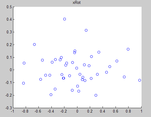
一、首先download这些二维数据,因为数据是以文本方式保存的,所以load的时候是以ascii码读入的。然后对输入样本进行协方差矩阵计算,并计算出该矩阵的SVD分解,得到其特征值向量,在原数据点上画出2条主方向,如下图所示:
二、将经过PCA降维后的新数据在坐标中显示出来,如下图所示:
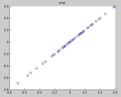
三、用新数据反过来重建原数据,其结果如下图所示:
四、使用PCA whitening的方法得到原数据的分布情况如:
五、使用ZCA whitening的方法得到的原数据的分布如下所示:
PCA whitening和ZCA whitening不同之处在于处理后的结果数据的方差不同,尽管不同维度的方差是相等的。
实验代码:
close all

%%================================================================
%% Step 0: Load data
%  We have provided the code to load data from pcaData.txt into x.
%  x is a 2 * 45 matrix, where the kth column x(:,k) corresponds to
%  the kth data point.Here we provide the code to load natural image data into x.
%  You do not need to change the code below.

x = load('pcaData.txt','-ascii');
figure(1);
scatter(x(1, :), x(2, :));
title('Raw data');


%%================================================================
%% Step 1a: Implement PCA to obtain U
%  Implement PCA to obtain the rotation matrix U, which is the eigenbasis
%  sigma.

% -------------------- YOUR CODE HERE --------------------
u = zeros(size(x, 1)); % You need to compute this
[n m] = size(x);
%x = x-repmat(mean(x,2),1,m);%预处理,均值为0
sigma = (1.0/m)*x*x';
[u s v] = svd(sigma);


% --------------------------------------------------------
hold on
plot([0 u(1,1)], [0 u(2,1)]);%画第一条线
plot([0 u(1,2)], [0 u(2,2)]);%第二条线
scatter(x(1, :), x(2, :));
hold off

%%================================================================
%% Step 1b: Compute xRot, the projection on to the eigenbasis
%  Now, compute xRot by projecting the data on to the basis defined
%  by U. Visualize the points by performing a scatter plot.

% -------------------- YOUR CODE HERE --------------------
xRot = zeros(size(x)); % You need to compute this
xRot = u'*x;


% --------------------------------------------------------

% Visualise the covariance matrix. You should see a line across the
% diagonal against a blue background.
figure(2);
scatter(xRot(1, :), xRot(2, :));
title('xRot');

%%================================================================
%% Step 2: Reduce the number of dimensions from 2 to 1.
%  Compute xRot again (this time projecting to 1 dimension).
%  Then, compute xHat by projecting the xRot back onto the original axes
%  to see the effect of dimension reduction

% -------------------- YOUR CODE HERE --------------------
k = 1; % Use k = 1 and project the data onto the first eigenbasis
xHat = zeros(size(x)); % You need to compute this
xHat = u*([u(:,1),zeros(n,1)]'*x);


% --------------------------------------------------------
figure(3);
scatter(xHat(1, :), xHat(2, :));
title('xHat');


%%================================================================
%% Step 3: PCA Whitening
%  Complute xPCAWhite and plot the results.

epsilon = 1e-5;
% -------------------- YOUR CODE HERE --------------------
xPCAWhite = zeros(size(x)); % You need to compute this
xPCAWhite = diag(1./sqrt(diag(s)+epsilon))*u'*x;


% --------------------------------------------------------
figure(4);
scatter(xPCAWhite(1, :), xPCAWhite(2, :));
title('xPCAWhite');

%%================================================================
%% Step 3: ZCA Whitening
%  Complute xZCAWhite and plot the results.

% -------------------- YOUR CODE HERE --------------------
xZCAWhite = zeros(size(x)); % You need to compute this
xZCAWhite = u*diag(1./sqrt(diag(s)+epsilon))*u'*x;

% --------------------------------------------------------
figure(5);
scatter(xZCAWhite(1, :), xZCAWhite(2, :));
title('xZCAWhite');

%% Congratulations! When you have reached this point, you are done!
%  You can now move onto the next PCA exercise. :)
参考资料:
Exercise:PCA in 2D
Deep learning:十二(PCA和whitening在二自然图像中的练习)
前言:
现在来用PCA,PCA Whitening对自然图像进行处理。这些理论知识参考前面的博文:Deep learning:十(PCA和whitening)。而本次试验的数据,步骤,要求等参考网页:http://deeplearning.stanford.edu/wiki/index.php/UFLDL_Tutorial 。实验数据是从自然图像中随机选取10000个12*12的patch,然后对这些patch进行99%的方差保留的PCA计算,最后对这些patch做PCA Whitening和ZCA Whitening,并进行比较。
实验环境:matlab2012a
实验过程及结果:
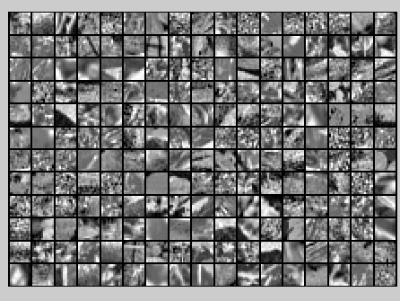
随机选取10000个patch,并显示其中204个patch,如下图所示:
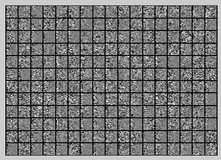
然后对这些patch做均值为0化操作得到如下图:
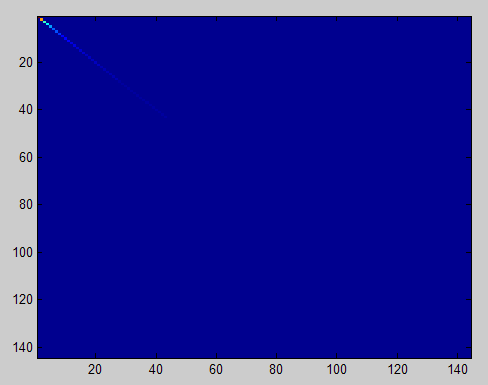
对选取出的patch做PCA变换得到新的样本数据,其新样本数据的协方差矩阵如下图所示:
保留99%的方差后的PCA还原原始数据,如下所示:
PCA Whitening后的图像如下:
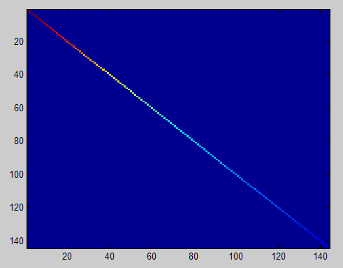
此时样本patch的协方差矩阵如下:
ZCA Whitening的结果如下:
实验代码及注释:
%%================================================================
%% Step 0a: Load data
%  Here we provide the code to load natural image data into x.
%  x will be a 144 * 10000 matrix, where the kth column x(:, k) corresponds to
%  the raw image data from the kth 12x12 image patch sampled.
%  You do not need to change the code below.

x = sampleIMAGESRAW();
figure('name','Raw images');
randsel = randi(size(x,2),204,1); % A random selection of samples for visualization
display_network(x(:,randsel));%为什么x有负数还可以显示?

%%================================================================
%% Step 0b: Zero-mean the data (by row)
%  You can make use of the mean and repmat/bsxfun functions.

% -------------------- YOUR CODE HERE --------------------
x = x-repmat(mean(x,1),size(x,1),1);%求的是每一列的均值
%x = x-repmat(mean(x,2),1,size(x,2));

%%================================================================
%% Step 1a: Implement PCA to obtain xRot
%  Implement PCA to obtain xRot, the matrix in which the data is expressed
%  with respect to the eigenbasis of sigma, which is the matrix U.


% -------------------- YOUR CODE HERE --------------------
xRot = zeros(size(x)); % You need to compute this
[n m] = size(x);
sigma = (1.0/m)*x*x';
[u s v] = svd(sigma);
xRot = u'*x;


%%================================================================
%% Step 1b: Check your implementation of PCA
%  The covariance matrix for the data expressed with respect to the basis U
%  should be a diagonal matrix with non-zero entries only along the main
%  diagonal. We will verify this here.
%  Write code to compute the covariance matrix, covar.
%  When visualised as an image, you should see a straight line across the
%  diagonal (non-zero entries) against a blue background (zero entries).

% -------------------- YOUR CODE HERE --------------------
covar = zeros(size(x, 1)); % You need to compute this
covar = (1./m)*xRot*xRot';

% Visualise the covariance matrix. You should see a line across the
% diagonal against a blue background.
figure('name','Visualisation of covariance matrix');
imagesc(covar);

%%================================================================
%% Step 2: Find k, the number of components to retain
%  Write code to determine k, the number of components to retain in order
%  to retain at least 99% of the variance.

% -------------------- YOUR CODE HERE --------------------
k = 0; % Set k accordingly
ss = diag(s);
% for k=1:m
%    if sum(s(1:k))./sum(ss) < 0.99
%        continue;
% end
%其中cumsum(ss)求出的是一个累积向量,也就是说ss向量值的累加值
%并且(cumsum(ss)/sum(ss))<=0.99是一个向量,值为0或者1的向量,为1表示满足那个条件
k = length(ss((cumsum(ss)/sum(ss))<=0.99));

%%================================================================
%% Step 3: Implement PCA with dimension reduction
%  Now that you have found k, you can reduce the dimension of the data by
%  discarding the remaining dimensions. In this way, you can represent the
%  data in k dimensions instead of the original 144, which will save you
%  computational time when running learning algorithms on the reduced
%  representation.
%
%  Following the dimension reduction, invert the PCA transformation to produce
%  the matrix xHat, the dimension-reduced data with respect to the original basis.
%  Visualise the data and compare it to the raw data. You will observe that
%  there is little loss due to throwing away the principal components that
%  correspond to dimensions with low variation.

% -------------------- YOUR CODE HERE --------------------
xHat = zeros(size(x));  % You need to compute this
xHat = u*[u(:,1:k)'*x;zeros(n-k,m)];

% Visualise the data, and compare it to the raw data
% You should observe that the raw and processed data are of comparable quality.
% For comparison, you may wish to generate a PCA reduced image which
% retains only 90% of the variance.

figure('name',['PCA processed images ',sprintf('(%d / %d dimensions)', k, size(x, 1)),'']);
display_network(xHat(:,randsel));
figure('name','Raw images');
display_network(x(:,randsel));

%%================================================================
%% Step 4a: Implement PCA with whitening and regularisation
%  Implement PCA with whitening and regularisation to produce the matrix
%  xPCAWhite.

epsilon = 0.1;
xPCAWhite = zeros(size(x));

% -------------------- YOUR CODE HERE --------------------
xPCAWhite = diag(1./sqrt(diag(s)+epsilon))*u'*x;
figure('name','PCA whitened images');
display_network(xPCAWhite(:,randsel));

%%================================================================
%% Step 4b: Check your implementation of PCA whitening
%  Check your implementation of PCA whitening with and without regularisation.
%  PCA whitening without regularisation results a covariance matrix
%  that is equal to the identity matrix. PCA whitening with regularisation
%  results in a covariance matrix with diagonal entries starting close to
%  1 and gradually becoming smaller. We will verify these properties here.
%  Write code to compute the covariance matrix, covar.
%
%  Without regularisation (set epsilon to 0 or close to 0),
%  when visualised as an image, you should see a red line across the
%  diagonal (one entries) against a blue background (zero entries).
%  With regularisation, you should see a red line that slowly turns
%  blue across the diagonal, corresponding to the one entries slowly
%  becoming smaller.

% -------------------- YOUR CODE HERE --------------------
covar = (1./m)*xPCAWhite*xPCAWhite';

% Visualise the covariance matrix. You should see a red line across the
% diagonal against a blue background.
figure('name','Visualisation of covariance matrix');
imagesc(covar);

%%================================================================
%% Step 5: Implement ZCA whitening
%  Now implement ZCA whitening to produce the matrix xZCAWhite.
%  Visualise the data and compare it to the raw data. You should observe
%  that whitening results in, among other things, enhanced edges.

xZCAWhite = zeros(size(x));

% -------------------- YOUR CODE HERE --------------------
xZCAWhite = u*xPCAWhite;

% Visualise the data, and compare it to the raw data.
% You should observe that the whitened images have enhanced edges.
figure('name','ZCA whitened images');
display_network(xZCAWhite(:,randsel));
figure('name','Raw images');
display_network(x(:,randsel));
参考资料:
http://deeplearning.stanford.edu/wiki/index.php/UFLDL_Tutorial
Deep learning:十三(Softmax Regression)
在前面的logistic regression博文Deep learning:四(logistic regression练习) 中,我们知道logistic regression很适合做一些非线性方面的分类问题,不过它只适合处理二分类的问题,且在给出分类结果时还会给出结果的概率。那么如果需要用类似的方法(这里类似的方法指的是输出分类结果并且给出概率值)来处理多分类问题的话该怎么扩展呢?本次要讲的就是对logstic regression扩展的一种多分类器,softmax regression。参考的内容为网页:http://deeplearning.stanford.edu/wiki/index.php/Softmax_Regression
在Logistic regression中,所学习的系统的程为:
其对应的损失函数为:
可以看出,给定一个样本,就输出一个概率值,该概率值表示的含义是这个样本属于类别’1’的概率,因为总共才有2个类别,所以另一个类别的概率直接用1减掉刚刚的结果即可。如果现在的假设是多分类问题,比如说总共有k个类别。在softmax regression中这时候的系统的方程为:
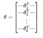
其中的参数sidta不再是列向量,而是一个矩阵,矩阵的每一行可以看做是一个类别所对应分类器的参数,总共有k行。所以矩阵sidta可以写成下面的形式:
此时,系统损失函数的方程为:
其中的1{.}是一个指示性函数,即当大括号中的值为真时,该函数的结果就为1,否则其结果就为0。
当然了,如果要用梯度下降法,牛顿法,或者L-BFGS法求得系统的参数的话,就必须求出损失函数的偏导函数,softmax regression中损失函数的偏导函数如下所示:
注意公式中的 是一个向量,表示的是针对第i个类别而求得的。所以上面的公式还只是一个类别的偏导公式,我们需要求出所有类别的偏导公式。
![]() 表示的是损失函数对第j个类别的第l个参数的偏导。
表示的是损失函数对第j个类别的第l个参数的偏导。
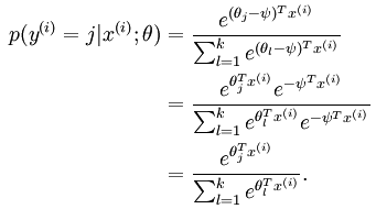
比较有趣的时,softmax regression中对参数的最优化求解不只一个,每当求得一个优化参数时,如果将这个参数的每一项都减掉同一个数,其得到的损失函数值也是一样的。这说明这个参数不是唯一解。用数学公式证明过程如下所示:
那这个到底是什么原因呢?从宏观上可以这么理解,因为此时的损失函数不是严格非凸的,也就是说在局部最小值点附近是一个”平坦”的,所以在这个参数附近的值都是一样的了。那么怎样避免这个问题呢?其实加入规则项就可以解决(比如说,用牛顿法求解时,hession矩阵如果没有加入规则项,就有可能不是可逆的从而导致了刚才的情况,如果加入了规则项后该hession矩阵就不会不可逆了),加入规则项后的损失函数表达式如下:
这个时候的偏导函数表达式如下所示:
接下来剩下的问题就是用数学优化的方法来求解了,另外还可以从数学公式的角度去理解softmax regression是logistic regression的扩展。
网页教程中还介绍了softmax regression和k binary classifiers之间的区别和使用条件。总结就这么一个要点:如果所需的分类类别之间是严格相互排斥的,也就是两种类别不能同时被一个样本占有,这时候应该使用softmax regression。反正,如果所需分类的类别之间允许某些重叠,这时候就应该使用binary classifiers了。
参考资料:
Deep learning:四(logistic regression练习)
http://deeplearning.stanford.edu/wiki/index.php/Softmax_Regression
Deep learning:十四(Softmax Regression练习)
前言:
这篇文章主要是用来练习softmax regression在多分类器中的应用,关于该部分的理论知识已经在前面的博文中Deep learning:十三(Softmax Regression)有所介绍。本次的实验内容是参考网页:http://deeplearning.stanford.edu/wiki/index.php/Exercise:Softmax_Regression。主要完成的是手写数字识别,采用的是MNIST手写数字数据库,其中训练样本有6万个,测试样本有1万个,且数字是0~9这10个。每个样本是一张小图片,大小为28*28的。
实验环境:matlab2012a
实验基础:
这次实验只用了softmax模型,也就是说没有隐含层,而只有输入层和输出层,因为实验中并没有提取出MINST样本的特征,而是直接用的原始像素特征。实验中主要是计算系统的损失函数和其偏导数,其计算公式如下所示:
一些matlab函数:
sparse:
生成一个稀疏矩阵,比如说sparse(A, B, k),,其中A和B是个向量,k是个常量。这里生成的稀疏矩阵的值都为参数k,稀疏矩阵位置值坐标点有A和B相应的位置点值构成。
full:
生成一个正常矩阵,一般都是利用稀疏矩阵来还原的。
实验错误:
按照作者给的starter code,结果连数据都加载不下来,出现如下错误提示:Error using permute Out of memory. Type HELP MEMORY for your options. 结果跟踪定位到loadMNISTImages.m文件中的images = permute(images,[2 1 3])这句代码,究其原因就是说images矩阵过大,在有限内存下不能够将其进行维度旋转变换。可是这个数据已经很小了,才几十兆而已,参考了很多out of memory的方法都不管用,后面直接把改句的前面一句代码images = reshape(images, numCols, numRows, numImages);改成images = reshape(images, numRows, numCols, numImages);反正实现的效果都是一样的。因为原因是内存问题,所以要么用64bit的matlab,要买自己对该函数去优化下,节省运行过程中的内存。
实验结果:
Accuracy: 92.640%
和网页教程中给的结果非常相近了。
实验主要部分代码:
softmaxExercise.m:
%% CS294A/CS294W Softmax Exercise

%  Instructions
%  ------------
%
%  This file contains code that helps you get started on the
%  softmax exercise. You will need to write the softmax cost function
%  in softmaxCost.m and the softmax prediction function in softmaxPred.m.
%  For this exercise, you will not need to change any code in this file,
%  or any other files other than those mentioned above.
%  (However, you may be required to do so in later exercises)

%%======================================================================
%% STEP 0: Initialise constants and parameters
%
%  Here we define and initialise some constants which allow your code
%  to be used more generally on any arbitrary input.
%  We also initialise some parameters used for tuning the model.

inputSize = 28 * 28; % Size of input vector (MNIST images are 28x28)
numClasses = 10;     % Number of classes (MNIST images fall into 10 classes)

lambda = 1e-4; % Weight decay parameter

%%======================================================================
%% STEP 1: Load data
%
%  In this section, we load the input and output data.
%  For softmax regression on MNIST pixels,
%  the input data is the images, and
%  the output data is the labels.
%

% Change the filenames if you've saved the files under different names
% On some platforms, the files might be saved as
% train-images.idx3-ubyte / train-labels.idx1-ubyte

images = loadMNISTImages('train-images.idx3-ubyte');
labels = loadMNISTLabels('train-labels.idx1-ubyte');
labels(labels==0) = 10; % Remap 0 to 10

inputData = images;

% For debugging purposes, you may wish to reduce the size of the input data
% in order to speed up gradient checking.
% Here, we create synthetic dataset using random data for testing

% DEBUG = true; % Set DEBUG to true when debugging.
DEBUG = false;
if DEBUG
    inputSize = 8;
    inputData = randn(8, 100);
    labels = randi(10, 100, 1);
end

% Randomly initialise theta
theta = 0.005 * randn(numClasses * inputSize, 1);%输入的是一个列向量

%%======================================================================
%% STEP 2: Implement softmaxCost
%
%  Implement softmaxCost in softmaxCost.m.

[cost, grad] = softmaxCost(theta, numClasses, inputSize, lambda, inputData, labels);

%%======================================================================
%% STEP 3: Gradient checking
%
%  As with any learning algorithm, you should always check that your
%  gradients are correct before learning the parameters.
%

if DEBUG
    numGrad = computeNumericalGradient( @(x) softmaxCost(x, numClasses, ...
                                    inputSize, lambda, inputData, labels), theta);

    % Use this to visually compare the gradients side by side
    disp([numGrad grad]);

    % Compare numerically computed gradients with those computed analytically
    diff = norm(numGrad-grad)/norm(numGrad+grad);
    disp(diff);
    % The difference should be small.
    % In our implementation, these values are usually less than 1e-7.

    % When your gradients are correct, congratulations!
end

%%======================================================================
%% STEP 4: Learning parameters
%
%  Once you have verified that your gradients are correct,
%  you can start training your softmax regression code using softmaxTrain
%  (which uses minFunc).

options.maxIter = 100;
%softmaxModel其实只是一个结构体,里面包含了学习到的最优参数以及输入尺寸大小和类别个数信息
softmaxModel = softmaxTrain(inputSize, numClasses, lambda, ...
                            inputData, labels, options);

% Although we only use 100 iterations here to train a classifier for the
% MNIST data set, in practice, training for more iterations is usually
% beneficial.

%%======================================================================
%% STEP 5: Testing
%
%  You should now test your model against the test images.
%  To do this, you will first need to write softmaxPredict
%  (in softmaxPredict.m), which should return predictions
%  given a softmax model and the input data.

images = loadMNISTImages('t10k-images.idx3-ubyte');
labels = loadMNISTLabels('t10k-labels.idx1-ubyte');
labels(labels==0) = 10; % Remap 0 to 10

inputData = images;
size(softmaxModel.optTheta)
size(inputData)

% You will have to implement softmaxPredict in softmaxPredict.m
[pred] = softmaxPredict(softmaxModel, inputData);

acc = mean(labels(:) == pred(:));
fprintf('Accuracy: %0.3f%%\n', acc * 100);

% Accuracy is the proportion of correctly classified images
% After 100 iterations, the results for our implementation were:
%
% Accuracy: 92.200%
%
% If your values are too low (accuracy less than 0.91), you should check
% your code for errors, and make sure you are training on the
% entire data set of 60000 28x28 training images
% (unless you modified the loading code, this should be the case)
softmaxCost.m
function [cost, grad] = softmaxCost(theta, numClasses, inputSize, lambda, data, labels)

% numClasses - the number of classes
% inputSize - the size N of the input vector
% lambda - weight decay parameter
% data - the N x M input matrix, where each column data(:, i) corresponds to
%        a single test set
% labels - an M x 1 matrix containing the labels corresponding for the input data
%

% Unroll the parameters from theta
theta = reshape(theta, numClasses, inputSize);%将输入的参数列向量变成一个矩阵

numCases = size(data, 2);%输入样本的个数
groundTruth = full(sparse(labels, 1:numCases, 1));%这里sparse是生成一个稀疏矩阵,该矩阵中的值都是第三个值1
                                                    %稀疏矩阵的小标由labels和1:numCases对应值构成
cost = 0;

thetagrad = zeros(numClasses, inputSize);

%% ---------- YOUR CODE HERE --------------------------------------
%  Instructions: Compute the cost and gradient for softmax regression.
%                You need to compute thetagrad and cost.
%                The groundTruth matrix might come in handy.

M = bsxfun(@minus,theta*data,max(theta*data, [], 1));
M = exp(M);
p = bsxfun(@rdivide, M, sum(M));
cost = -1/numCases * groundTruth(:)' * log(p(:)) + lambda/2 * sum(theta(:) .^ 2);
thetagrad = -1/numCases * (groundTruth - p) * data' + lambda * theta;


% ------------------------------------------------------------------
% Unroll the gradient matrices into a vector for minFunc
grad = [thetagrad(:)];
end
softmaxTrain.m:
function [softmaxModel] = softmaxTrain(inputSize, numClasses, lambda, inputData, labels, options)
%softmaxTrain Train a softmax model with the given parameters on the given
% data. Returns softmaxOptTheta, a vector containing the trained parameters
% for the model.
%
% inputSize: the size of an input vector x^(i)
% numClasses: the number of classes
% lambda: weight decay parameter
% inputData: an N by M matrix containing the input data, such that
%            inputData(:, c) is the cth input
% labels: M by 1 matrix containing the class labels for the
%            corresponding inputs. labels(c) is the class label for
%            the cth input
% options (optional): options
%   options.maxIter: number of iterations to train for

if ~exist('options', 'var')
    options = struct;
end

if ~isfield(options, 'maxIter')
    options.maxIter = 400;
end

% initialize parameters
theta = 0.005 * randn(numClasses * inputSize, 1);

% Use minFunc to minimize the function
addpath minFunc/
options.Method = 'lbfgs'; % Here, we use L-BFGS to optimize our cost
                          % function. Generally, for minFunc to work, you
                          % need a function pointer with two outputs: the
                          % function value and the gradient. In our problem,
                          % softmaxCost.m satisfies this.
minFuncOptions.display = 'on';

[softmaxOptTheta, cost] = minFunc( @(p) softmaxCost(p, ...
                                   numClasses, inputSize, lambda, ...
                                   inputData, labels), ...
                              theta, options);

% Fold softmaxOptTheta into a nicer format
softmaxModel.optTheta = reshape(softmaxOptTheta, numClasses, inputSize);
softmaxModel.inputSize = inputSize;
softmaxModel.numClasses = numClasses;

end
softmaxPredict.m:
function [pred] = softmaxPredict(softmaxModel, data)

% softmaxModel - model trained using softmaxTrain
% data - the N x M input matrix, where each column data(:, i) corresponds to
%        a single test set
%
% Your code should produce the prediction matrix
% pred, where pred(i) is argmax_c P(y(c) | x(i)).

% Unroll the parameters from theta
theta = softmaxModel.optTheta;  % this provides a numClasses x inputSize matrix
pred = zeros(1, size(data, 2));

%% ---------- YOUR CODE HERE --------------------------------------
%  Instructions: Compute pred using theta assuming that the labels start
%                from 1.


[nop, pred] = max(theta * data);
%  pred= max(peed_temp);


% ---------------------------------------------------------------------

end
参考资料:
Deep learning:十三(Softmax Regression)
http://deeplearning.stanford.edu/wiki/index.php/Exercise:Softmax_Regression
Deep learning:十五(Self-Taught Learning练习)
前言:
本次实验主要是练习soft- taught learning的实现。参考的资料为网页:http://deeplearning.stanford.edu/wiki/index.php/Exercise:Self-Taught_Learning。Soft-taught leaning是用的无监督学习来学习到特征提取的参数,然后用有监督学习来训练分类器。这里分别是用的sparse autoencoder和softmax regression。实验的数据依旧是手写数字数据库MNIST Dataset.
实验基础:
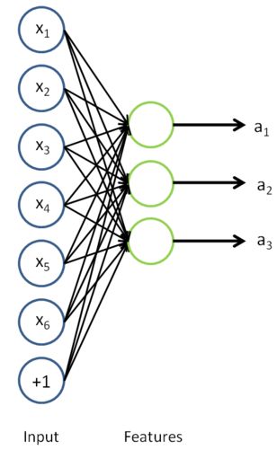
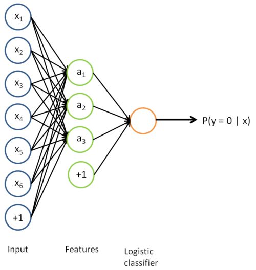
从前面的知识可以知道,sparse autoencoder的输出应该是和输入数据尺寸大小一样的,且很相近,那么我们训练出的sparse autoencoder模型该怎样提取出特征向量呢?其实输入样本经过sparse code提取出特征的表达式就是隐含层的输出了,首先来看看前面的经典sparse code模型,如下图所示:
拿掉那个后面的输出层后,隐含层的值就是我们所需要的特征值了,如下图所示:
从教程中可知,在unsupervised learning中有两个观点需要特别注意,一个是self-taught learning,一个是semi-supervised learning。Self-taught learning是完全无监督的。教程中有举了个例子,很好的说明了这个问题,比如说我们需要设计一个系统来分类出轿车和摩托车。如果我们给出的训练样本图片是自然界中随便下载的(也就是说这些图片中可能有轿车和摩托车,有可能都没有,且大多数情况下是没有的),然后使用的是这些样本来特征模型的话,那么此时的方法就叫做self-taught learning。如果我们训练的样本图片都是轿车和摩托车的图片,只是我们不知道哪张图对应哪种车,也就是说没有标注,此时的方法不能叫做是严格的unsupervised feature,只能叫做是semi-supervised learning。
一些matlab函数:
numel:
比如说n = numel(A)表示返回矩阵A中元素的个数。
unique:
unique为找出向量中的非重复元素并进行排序后输出。
实验结果:
采用数字5~9的样本来进行无监督训练,采用的方法是sparse autoencoder,可以提取出这些数据的权值,权值转换成图片显示如下:
但是本次实验主要是进行0~4这5个数字的分类,虽然进行无监督训练用的是数字5~9的训练样本,这依然不会影响后面的结果。只是后面的分类器设计是用的softmax regression,所以是有监督的。最后据官网网页上的结果精度是98%,而直接用原始的像素点进行分类器的设计不仅效果要差(才96%),而且训练的速度也会变慢不少。
实验主要部分代码:
stlExercise.m:
%% CS294A/CS294W Self-taught Learning Exercise

%  Instructions
%  ------------
%
%  This file contains code that helps you get started on the
%  self-taught learning. You will need to complete code in feedForwardAutoencoder.m
%  You will also need to have implemented sparseAutoencoderCost.m and
%  softmaxCost.m from previous exercises.
%
%% ======================================================================
%  STEP 0: Here we provide the relevant parameters values that will
%  allow your sparse autoencoder to get good filters; you do not need to
%  change the parameters below.

inputSize  = 28 * 28;
numLabels  = 5;
hiddenSize = 200;
sparsityParam = 0.1; % desired average activation of the hidden units.
                     % (This was denoted by the Greek alphabet rho, which looks like a lower-case "p",
                     %  in the lecture notes).
lambda = 3e-3;       % weight decay parameter
beta = 3;            % weight of sparsity penalty term
maxIter = 400;

%% ======================================================================
%  STEP 1: Load data from the MNIST database
%
%  This loads our training and test data from the MNIST database files.
%  We have sorted the data for you in this so that you will not have to
%  change it.

% Load MNIST database files
mnistData   = loadMNISTImages('train-images.idx3-ubyte');
mnistLabels = loadMNISTLabels('train-labels.idx1-ubyte');

% Set Unlabeled Set (All Images)

% Simulate a Labeled and Unlabeled set
labeledSet   = find(mnistLabels >= 0 & mnistLabels <= 4);
unlabeledSet = find(mnistLabels >= 5);

%%增加的一行代码
unlabeledSet = unlabeledSet(1:end/3);

numTest = round(numel(labeledSet)/2);%拿一半的样本来训练%
numTrain = round(numel(labeledSet)/3);
trainSet = labeledSet(1:numTrain);
testSet  = labeledSet(numTrain+1:2*numTrain);

unlabeledData = mnistData(:, unlabeledSet);%%为什么这两句连在一起都要出错呢?
% pack;
trainData   = mnistData(:, trainSet);
trainLabels = mnistLabels(trainSet)' + 1; % Shift Labels to the Range 1-5

% mnistData2 = mnistData;
testData   = mnistData(:, testSet);
testLabels = mnistLabels(testSet)' + 1;   % Shift Labels to the Range 1-5

% Output Some Statistics
fprintf('# examples in unlabeled set: %d\n', size(unlabeledData, 2));
fprintf('# examples in supervised training set: %d\n\n', size(trainData, 2));
fprintf('# examples in supervised testing set: %d\n\n', size(testData, 2));

%% ======================================================================
%  STEP 2: Train the sparse autoencoder
%  This trains the sparse autoencoder on the unlabeled training
%  images.

%  Randomly initialize the parameters
theta = initializeParameters(hiddenSize, inputSize);

%% ----------------- YOUR CODE HERE ----------------------
%  Find opttheta by running the sparse autoencoder on
%  unlabeledTrainingImages

opttheta = theta;
addpath minFunc/
options.Method = 'lbfgs';
options.maxIter = 400;
options.display = 'on';
[opttheta, loss] = minFunc( @(p) sparseAutoencoderLoss(p, ...
      inputSize, hiddenSize, ...
      lambda, sparsityParam, ...
      beta, unlabeledData), ...
      theta, options);


%% -----------------------------------------------------

% Visualize weights
W1 = reshape(opttheta(1:hiddenSize * inputSize), hiddenSize, inputSize);
display_network(W1');

%%======================================================================
%% STEP 3: Extract Features from the Supervised Dataset
%
%  You need to complete the code in feedForwardAutoencoder.m so that the
%  following command will extract features from the data.

trainFeatures = feedForwardAutoencoder(opttheta, hiddenSize, inputSize, ...
                                       trainData);

testFeatures = feedForwardAutoencoder(opttheta, hiddenSize, inputSize, ...
                                       testData);

%%======================================================================
%% STEP 4: Train the softmax classifier

softmaxModel = struct;
%% ----------------- YOUR CODE HERE ----------------------
%  Use softmaxTrain.m from the previous exercise to train a multi-class
%  classifier.

%  Use lambda = 1e-4 for the weight regularization for softmax
lambda = 1e-4;
inputSize = hiddenSize;
numClasses = numel(unique(trainLabels));%unique为找出向量中的非重复元素并进行排序

% You need to compute softmaxModel using softmaxTrain on trainFeatures and
% trainLabels


% You need to compute softmaxModel using softmaxTrain on trainFeatures and
% trainLabels

options.maxIter = 100;
softmaxModel = softmaxTrain(inputSize, numClasses, lambda, ...
                            trainFeatures, trainLabels, options);


%% -----------------------------------------------------


%%======================================================================
%% STEP 5: Testing

%% ----------------- YOUR CODE HERE ----------------------
% Compute Predictions on the test set (testFeatures) using softmaxPredict
% and softmaxModel


[pred] = softmaxPredict(softmaxModel, testFeatures);


%% -----------------------------------------------------

% Classification Score
fprintf('Test Accuracy: %f%%\n', 100*mean(pred(:) == testLabels(:)));

% (note that we shift the labels by 1, so that digit 0 now corresponds to
%  label 1)
%
% Accuracy is the proportion of correctly classified images
% The results for our implementation was:
%
% Accuracy: 98.3%
%
%
feedForwardAutoencoder.m:
function [activation] = feedForwardAutoencoder(theta, hiddenSize, visibleSize, data)

% theta: trained weights from the autoencoder
% visibleSize: the number of input units (probably 64)
% hiddenSize: the number of hidden units (probably 25)
% data: Our matrix containing the training data as columns.  So, data(:,i) is the i-th training example.

% We first convert theta to the (W1, W2, b1, b2) matrix/vector format, so that this
% follows the notation convention of the lecture notes.

W1 = reshape(theta(1:hiddenSize*visibleSize), hiddenSize, visibleSize);
b1 = theta(2*hiddenSize*visibleSize+1:2*hiddenSize*visibleSize+hiddenSize);

%% ---------- YOUR CODE HERE --------------------------------------
%  Instructions: Compute the activation of the hidden layer for the Sparse Autoencoder.
activation  = sigmoid(W1*data+repmat(b1,[1,size(data,2)]));

%-------------------------------------------------------------------

end

%-------------------------------------------------------------------
% Here's an implementation of the sigmoid function, which you may find useful
% in your computation of the costs and the gradients.  This inputs a (row or
% column) vector (say (z1, z2, z3)) and returns (f(z1), f(z2), f(z3)).

function sigm = sigmoid(x)
    sigm = 1 ./ (1 + exp(-x));
end
参考资料:
http://deeplearning.stanford.edu/wiki/index.php/Exercise:Self-Taught_Learning
MNIST Dataset
Deep learning:十六(deep networks)
本节参考的是网页http://deeplearning.stanford.edu/wiki/index.php/UFLDL_Tutorial中关于Building Deep Networks for Classification一节的介绍。分下面2大部分内容:
1. 从self-taught到deep networks:
从前面的关于self-taught learning介绍(Deep learning:十五(Self-Taught Learning练习))可以看到,该ML方法在特征提取方面是完全用的无监督方法,本次要讲的就是在上面的基础上再用有监督的方法继续对网络的参数进行微调,这样就可以得到更好的效果了。把self-taught learning的两个步骤合在一起的结构图如下所示:
很显然,上面是一个多层神经网络,三层。
一般的,前面的无监督学习到的模型参数可以当做是有监督学习参数的初始化值,这样当我们用有大量的标注了的数据时,就可以采用梯度下降等方法来继续优化参数了,因为有了刚刚的初始化参数,此时的优化结果一般都能收敛到比较好的局部最优解。如果是随机初始化模型的参数值的话,那么在多层神经网络中一般很难收敛到局部较好值,因为多层神经网络的系统函数是非凸的。
那么该什么时候使用微调技术来调整无监督学习的结果呢?只有我们有大量标注的样本下才可以。当我们有大量无标注的样本,但有一小部分标注的样本时也是不适合使用微调技术的。如果我们不想使用微调技术的话,那么在第三层分类器的设计时,应该采用级联的表达方式,也就是说学习到的结果和原始的特征值一起输入。当然了,如果采用了微调技术,则效果更好,就不需要继续用级联的特征表达了。
2. Deep networks小综述:
如果使用多层神经网络的话,那么将可以得到对输入更复杂的函数表示,因为神经网络的每一层都是上一层的非线性变换。当然,此时要求每一层的activation函数是非线性的,否则就没有必要用多层了。
Deep networks的优点:
一、比单层神经网络能学习到更复杂的表达。比如说用k层神经网络能学习到的函数(且每层网络节点个数时多项式的)如果要用k-1层神经网络来学习,则这k-1层神经网络节点的个数必须是指数级庞大的数字。
二、不同层的网络学习到的特征是由最底层到最高层慢慢上升的。比如在图像的学习中,第一个隐含层层网络可能学习的是边缘特征,第二隐含层就学习到的是轮廓什么的,后面的就会更高级有可能是图像目标中的一个部位,也就是是底层隐含层学习底层特征,高层隐含层学习高层特征。
三、这种多层神经网络的结构和人体大脑皮层的多层感知结构非常类似,所以说有一定的生物理论基础。
Deep networks的缺点:
一、网络的层次越深,所需的训练样本数越多,如果是用有监督学习的话,那么这些样本就更难获取,因为要进行各种标注。但是如果样本数太少的话,就很容易产生过拟合现象。
二、因为多层神经网络的参数优化问题是一个高阶非凸优化问题,这个问题通常收敛到一个比较差的局部解,普通的优化算法一般都效果不好。也就是说,参数的优化问题是个难点。
三、梯度扩散问题。因为当网络层次比较深时,在计算损失函数的偏导时一般需要使用BP算法,但是这些梯度值随着深度慢慢靠前而显著下降,这样导致前面的网络对最终的损失函数的贡献很小。这样的话前面的权值更新速度就非常非常慢了。一个理论上比较好的解决方法是将后面网络的结构的神经元的个数提高非常多,以至于它不会影响前面网络的结构的学习。但这样岂不是和低深度的网络结构一样了吗?所以不妥。
所以一般都是采用的层次贪婪训练方法来训练网络的参数,即先训练网络的第一个隐含层,然后接着训练第二个,第三个…最后用这些训练好的网络参数值作为整体网络参数的初始值。这样的好处是数据更容易获取,因为前面的网络层次基本都用无监督的方法获得,很容易,只有最后一个输出层需要有监督的数据。另外由于无监督学习其实隐形之中已经提供了一些输入数据的先验知识,所以此时的参数初始化值一般都能得到最终比较好的局部最优解。比较常见的一种层次贪婪训练方法就是stacked autoencoders。它的编码公式如下所示:
解码公式如下:
最后的就是用stacked autoencoders学习到的参数来初始化整个网络了,此时整个网络可以看做是一个单一的神经网络模型,只是它是多层的而已,而通常的BP算法是对任意层的网络都有效的。最后的参数调整步骤和前面学习到的稀疏编码模型是一样的。其过程截图如下:
参考资料:
http://deeplearning.stanford.edu/wiki/index.php/UFLDL_Tutorial
Deep learning:十五(Self-Taught Learning练习)
Deep learning:十七(Linear Decoders,Convolution和Pooling)
本文主要是学习下Linear Decoder已经在大图片中经常采用的技术convolution和pooling,分别参考网页http://deeplearning.stanford.edu/wiki/index.php/UFLDL_Tutorial中对应的章节部分。
Linear Decoders:
以三层的稀疏编码神经网络而言,在sparse autoencoder中的输出层满足下面的公式:
从公式中可以看出,a3的输出值是f函数的输出,而在普通的sparse autoencoder中f函数一般为sigmoid函数,所以其输出值的范围为(0,1),所以可以知道a3的输出值范围也在0到1之间。另外我们知道,在稀疏模型中的输出层应该是尽量和输入层特征相同,也就是说a3=x1,这样就可以推导出x1也是在0和1之间,那就是要求我们对输入到网络中的数据要先变换到0和1之间,这一条件虽然在有些领域满足,比如前面实验中的MINIST数字识别。但是有些领域,比如说使用了PCA Whitening后的数据,其范围却不一定在0和1之间。因此Linear Decoder方法就出现了。Linear Decoder是指在隐含层采用的激发函数是sigmoid函数,而在输出层的激发函数采用的是线性函数,比如说最特别的线性函数——等值函数。此时,也就是说输出层满足下面公式:
![]()
这样在用BP算法进行梯度的求解时,只需要更改误差点的计算公式而已,改成如下公式:
Convolution:
在了解convolution前,先认识下为什么要从全部连接网络发展到局部连接网络。在全局连接网络中,如果我们的图像很大,比如说为96*96,隐含层有要学习100个特征,则这时候把输入层的所有点都与隐含层节点连接,则需要学习10^6个参数,这样的话在使用BP算法时速度就明显慢了很多。
所以后面就发展到了局部连接网络,也就是说每个隐含层的节点只与一部分连续的输入点连接。这样的好处是模拟了人大脑皮层中视觉皮层不同位置只对局部区域有响应。局部连接网络在神经网络中的实现使用convolution的方法。它在神经网络中的理论基础是对于自然图像来说,因为它们具有稳定性,即图像中某个部分的统计特征和其它部位的相似,因此我们学习到的某个部位的特征也同样适用于其它部位。
下面具体看一个例子是怎样实现convolution的,假如对一张大图片Xlarge的数据集,r*c大小,则首先需要对这个数据集随机采样大小为a*b的小图片,然后用这些小图片patch进行学习(比如说sparse autoencoder),此时的隐含节点为k个。因此最终学习到的特征数为:
此时的convolution移动是有重叠的。
Pooling:
虽然按照convolution的方法可以减小不少需要训练的网络参数,比如说96*96,,100个隐含层的,采用8*8patch,也100个隐含层,则其需要训练的参数个数减小到了10^3,大大的减小特征提取过程的困难。但是此时同样出现了一个问题,即它的输出向量的维数变得很大,本来完全连接的网络输出只有100维的,现在的网络输出为89*89*100=792100维,大大的变大了,这对后面的分类器的设计同样带来了困难,所以pooling方法就出现了。
为什么pooling的方法可以工作呢?首先在前面的使用convolution时是利用了图像的stationarity特征,即不同部位的图像的统计特征是相同的,那么在使用convolution对图片中的某个局部部位计算时,得到的一个向量应该是对这个图像局部的一个特征,既然图像有stationarity特征,那么对这个得到的特征向量进行统计计算的话,所有的图像局部块应该也都能得到相似的结果。对convolution得到的结果进行统计计算过程就叫做pooling,由此可见pooling也是有效的。常见的pooling方法有max pooling和average pooling等。并且学习到的特征具有旋转不变性(这个原因暂时没能理解清楚)。
从上面的介绍可以简单的知道,convolution是为了解决前面无监督特征提取学习计算复杂度的问题,而pooling方法是为了后面有监督特征分类器学习的,也是为了减小需要训练的系统参数(当然这是在普遍例子中的理解,也就是说我们采用无监督的方法提取目标的特征,而采用有监督的方法来训练分类器)。
参考资料:
http://deeplearning.stanford.edu/wiki/index.php/UFLDL_Tutorial
Deep learning:十八(关于随机采样)
由于最近在看deep learning中的RBMs网络,而RBMs中本身就有各种公式不好理解,再来几个Gibbs采样,就更令人头疼了。所以还是觉得先看下Gibbs采样的理论知识。经过调查发现Gibbs是随机采样中的一种。所以本节也主要是简单层次的理解下随机采用知识。参考的知识是博客随机模拟的基本思想和常用采样方法(sampling),该博文是网上找到的解释得最通俗的。其实学校各种带数学公式的知识时,最好有学者能用通俗易懂的语言介绍,这对入门学者来说极其重要。当然了,还参考了网页http://www.jdl.ac.cn/user/lyqing/StatLearning/StatlLearning_handout.html中的一些资料。
采样是指我们知道一个样本x(大多数情况下是多维的)的概率分布函数,要通过这个函数来产生多个样本点集合。有的人可能会问,这有什么难的,matlaab等工具不是有命令来产生各种分布的样本么?比如说均值分布,正太分布的。对,确实没错,但这些分布样本点的产生也不是很容易的,需要精心设计。如果把函数域中的每个函数都去花精力设计它的样本产生方法,岂不是很费力。所以就出现了随机采样的方法,只要能逼近理论结果值就ok了。当然了,这只是随机采用方法出现的一种原因,纯属个人理解,肯定还有不少其它方面的因素的。
分下面几个部分来介绍常见的随机采样方法:
一、拒绝——接受采样
该方法是用一个我们很容易采样到的分布去模拟需要采样的分布。它要满足一些条件,如下:
其具体的采集过程如下所示:
几何上的解释如下:
由上面的解释可知,其实是在给定一个样本x的情况下,然后又随机选取一个y值,该y值是在轮廓线Mq(x)下随机产生的,如果该y值落在2条曲线之间,则被拒绝,否则就会被接受。这很容易理解,关于其理论的各种推导这里就免了,太枯燥了,哈哈。
二、重要性采样。
我对重要性采样的理解是该方法目的并不是用来产生一个样本的,而是求一个函数的定积分的,只是因为该定积分的求法是通过对另一个叫容易采集分布的随机采用得到的(本人研究比较浅,暂时只能这么理解着)。如下图所示:
其中通过对q(x)的随机采样,得到大量的样本x,然后求出f(x)*w(x)的均值,最终得出积分I值。其中的w(x)也就是重要性了,此时如果q(x)概率大,则得到的x样本数就多,这样w(x)的值也就多了,也间接体现了它越重要。
三、 Metropolis-Hasting
该方法是用一个建议分布以一定概率来更新样本,有点类似拒绝——接受采样。其过程如下所示:
四、Gibbs采样
Gibss采用是需要知道样本中一个属性在其它所有属性下的条件概率,然后利用这个条件概率来分布产生各个属性的样本值。其过程如下所示:
参考资料:
随机模拟的基本思想和常用采样方法(sampling)
http://www.jdl.ac.cn/user/lyqing/StatLearning/StatlLearning_handout.html
Deep learning:十九(RBM简单理解)
这篇博客主要用来简单介绍下RBM网络,因为deep learning中的一个重要网络结构DBN就可以由RBM网络叠加而成,所以对RBM的理解有利于我们对DBN算法以及deep learning算法的进一步理解。Deep learning是从06年开始火得,得益于大牛Hinton的文章,不过这位大牛的文章比较晦涩难懂,公式太多,对于我这种菜鸟级别来说读懂它的paper压力太大。纵观大部分介绍RBM的paper,都会提到能量函数。因此有必要先了解下能量函数的概念。参考网页http://202.197.191.225:8080/30/text/chapter06/6_2t24.htm关于能量函数的介绍:
一个事物有相应的稳态,如在一个碗内的小球会停留在碗底,即使受到扰动偏离了碗底,在扰动消失后,它会回到碗底。学过物理的人都知道,稳态是它势能最低的状态。因此稳态对应与某一种能量的最低状态。将这种概念引用到Hopfield网络中去,Hopfield构造了一种能量函数的定义。这是他所作的一大贡献。引进能量函数概念可以进一步加深对这一类动力系统性质的认识,可以把求稳态变成一个求极值与优化的问题,从而为Hopfield网络找到一个解优化问题的应用。
下面来看看RBM网络,其结构图如下所示:
可以看到RBM网络共有2层,其中第一层称为可视层,一般来说是输入层,另一层是隐含层,也就是我们一般指的特征提取层。在一般的文章中,都把这2层的节点看做是二值的,也就是只能取0或1,当然了,RBM中节点是可以取实数值的,这里取二值只是为了更好的解释各种公式而已。在前面一系列的博文中可以知道,我们设计一个网络结构后,接下来就应该想方设法来求解网络中的参数值。而这又一般是通过最小化损失函数值来解得的,比如在autoencoder中是通过重构值和输入值之间的误差作为损失函数(当然了,一般都会对参数进行规制化的);在logistic回归中损失函数是与输出值和样本标注值的差有关。那么在RBM网络中,我们的损失函数的表达式是什么呢,损失函数的偏导函数又该怎么求呢?
在了解这个问题之前,我们还是先从能量函数出发。针对RBM模型而言,输入v向量和隐含层输出向量h之间的能量函数值为:
而这2者之间的联合概率为:
其中Z是归一化因子,其值为:
这里为了习惯,把输入v改成函数的自变量x,则关于x的概率分布函数为:
令一个中间变量F(x)为:
则x的概率分布可以重新写为:
这时候它的偏导函数取负后为:
从上面能量函数的抽象介绍中可以看出,如果要使系统(这里即指RBM网络)达到稳定,则应该是系统的能量值最小,由上面的公式可知,要使能量E最小,应该使F(x)最小,也就是要使P(x)最大。因此此时的损失函数可以看做是-P(x),且求导时需要是加上负号的。
另外在图RBM中,可以很容易得到下面的概率值公式:
此时的F(v)为(也就是F(x)):
这个函数也被称做是自由能量函数。另外经过一些列的理论推导,可以求出损失函数的偏导函数公式为:
很明显,我们这里是吧-P(v)当成了损失函数了。另外,估计大家在看RBM相关文章时,一定会介绍Gibbs采样的知识,关于Gibbs内容可以简单参考上一篇博文:Deep learning:十八(关于随机采样)。那么为什么要用随机采用来得到数据呢,我们不是都有训练样本数据了么?其实这个问题我也一直没弄明白。在看过一些简单的RBM代码后,暂时只能这么理解:在上面文章最后的求偏导公式里,是两个数的减法,按照一般paper上所讲,这个被减数等于输入样本数据的自由能量函数期望值,而减数是模型产生样本数据的自由能量函数期望值。而这个模型样本数据就是利用Gibbs采样获得的,大概就是用原始的数据v输入到网络,计算输出h(1),然后又反推v(1),继续计算h(2),…,当最后反推出的v(k)和k比较接近时停止,这个时候的v(k)就是模型数据样本了。
也可以参考博文浅谈Deep Learning的基本思想和方法来理解:假设有一个二部图,每一层的节点之间没有链接,一层是可视层,即输入数据层(v),一层是隐藏层(h),如果假设所有的节点都是二值变量节点(只能取0或者1值),同时假设全概率分布p(v, h)满足Boltzmann 分布,我们称这个模型是Restrict Boltzmann Machine (RBM)。下面我们来看看为什么它是Deep Learning方法。首先,这个模型因为是二部图,所以在已知v的情况下,所有的隐藏节点之间是条件独立的,即p(h|v) =p(h1|v).....p(hn|v)。同理,在已知隐藏层h的情况下,所有的可视节点都是条件独立的,同时又由于所有的v和h满足Boltzmann 分布,因此,当输入v的时候,通过p(h|v) 可以得到隐藏层h,而得到隐藏层h之后,通过p(v|h) 又能得到可视层,通过调整参数,我们就是要使得从隐藏层得到的可视层v1与原来的可视层v如果一样,那么得到的隐藏层就是可视层另外一种表达,因此隐藏层可以作为可视层输入数据的特征,所以它就是一种Deep Learning方法。
参考资料:
http://202.197.191.225:8080/30/text/chapter06/6_2t24.htm
http://deeplearning.net/tutorial/rbm.html
http://edchedch.wordpress.com/2011/07/18/introduction-to-restricted-boltzmann-machines/
Deep learning:十八(关于随机采样)
浅谈Deep Learning的基本思想和方法
Deep learning:二十(无监督特征学习中关于单层网络的分析)
本文是读Ng团队的论文” An Analysis of Single-Layer Networks in Unsupervised Feature Learning”后的分析,主要是针对一个隐含层的网络结构进行分析的,分别对比了4种网络结构,k-means, sparse autoencoder, sparse rbm, gmm。最后作者得出了下面几个结论:1. 网络中隐含层神经元节点的个数,采集的密度(也就是convolution时的移动步伐)和感知区域大小对最终特征提取效果的影响很大,甚至比网络的层次数,deep learning学习算法本身还要重要。2. Whitening在预处理过程中还是很有必要的。3. 在以上4种实验算法中,k-means效果竟然最好。因此在最后作者给出结论时的建议是,尽量使用whitening对数据进行预处理,每一层训练更多的特征数,采用更密集的方法对数据进行采样。
NORB:
该数据库参考网页:http://www.cs.nyu.edu/~ylclab/data/norb-v1.0/index.html。该数据库是由5种玩具模型的图片构成:4只脚的动物,飞机,卡车,人,小轿车,由于每一种玩具模型又有几种,所以总共是有60种类别。总共用2个摄像头,在9种高度和18种方位角拍摄的。部分截图如下:
CIFAR-10:
该数据库参考网页:http://www.cs.toronto.edu/~kriz/cifar.html。这个数据库也是图片识别的,共有10个类别,飞机,鸟什么的。每一个类别的图片有6000张,其中5000张用于训练,1000张用于测试。图片的大小为32*32的。部分截图如下:
一般在deep learning中,最大的缺陷就是有很多参数需要调整,比如说学习速率,稀疏度惩罚系数,权值惩罚系数,momentum(不懂怎么翻译,好像rbm中需要用到)等。而这些参数最终的确定需要通过交叉验证获得,本身这样的结构训练起来所用时间就长,这么多参数要用交叉验证来获取时间就更多了。所以本文得出的结论用kmeans效果那么好,且无需有这些参数要考虑。
下面是上面4种算法的一些简单介绍:
Sparse autoencoder:
其网络函数表达式如下:
Sparse RBM:
和Sparse auto-encoder函数表达类似,只不过求解参数时的思想不同而已。另外在Sparse RBM中,参数优化主要用CD(对比散度)算法。而在Sparse autoencoder在参数优化时主要使用bp算法。
K-means聚类:
如果是用hard-kmeans的话,其目标函数公式如下:
其中c(j)为聚类得到的类别中心点。
如果用soft-kmeasn的话,则表达式如下:
其中Zk的计算公式如下:
![]()
Uk为元素z的均值。
GMM:
其目标函数表达式如下:
分类算法统一采用的是svm。
当训练出特征提取的网络参数后,就可以对输入的图片进行特征提取了,其特征提取的示意图如下所示:
实验结果:
首先来看看有无whitening学习到的图片特征在这4种情况下的显示如下:
可以看出whitening后学习到更多的细节,且whitening后几种算法都能学到类似gabor滤波器的效果,因此并不一定是deep learning的结构才可以学到这些特性。
下面的这个曲线图表明,隐含层节点的个数越多则最后的识别率会越高,并且可以看出soft kmeans的效果要最好。
从下面的曲线可以看出当stride越小时,效果越好,不过作者建议最好将该参数设置为大于1,因为如果设置太小,则计算量会增大,比如在sparse coding中,每次测试图片输入时,对小patch进行convolution时都要经过数学优化来求其输出(和autoencoder,rbm等deep learning算法不同),所以计算量会特别大。不过当stride值越大则识别率会显著下降。
而这下面这张图则表明当Receptive filed size为6时,效果最好。不过作者也认为这不一定,因为如果把该参数调大,这意味着需要更多的训练样本才有可能体会出该参数的作用,因此这个感知器区域即使比较小,也是可以学到不错的特征的。
参考资料:
An Analysis of Single-Layer Networks in Unsupervised Feature Learning, Adam Coates, Honglak Lee, and Andrew Y. Ng. In AISTATS 14, 2011.
http://www.cs.nyu.edu/~ylclab/data/norb-v1.0/index.html
http://www.cs.toronto.edu/~kriz/cifar.html
Deep learning:二十一(随机初始化在无监督特征学习中的作用)
这又是Ng团队的一篇有趣的paper。Ng团队在上篇博客文章Deep learning:二十(无监督特征学习中关于单层网络的分析)中给出的结论是:网络中隐含节点的个数,convolution尺寸和移动步伐等参数比网络的层次比网络参数的学习算法本身还要重要,也就是说即使是使用单层的网络,只要隐含层的节点数够大,convolution尺寸和移动步伐较小,用简单的算法(比如kmeans算法)也可取得不亚于其它复杂的deep learning最优效果算法。而在本文On random weights and unsupervised feature learning中又提出了个新观点:即根本就无需通过那些复杂且消耗大量时间去训练网络的参数的deep learning算法,我们只需随机给网络赋一组参数值,其最终取得的特征好坏不比那些预训练和仔细调整后得到的效果些,而且这样还可以减少大量的训练时间。
以上两个结论不免能引起大家很多疑惑,既然这么多人去研究深度学习,提出了那么多深度学习的算法,并构建了各种深度网络结构,而现在却发现只需用单层网络,不需要任何深度学习算法,就可以取得接近深度学习算法的最优值,甚至更好。那么深度学习还有必要值得研究么?单层网络也就没有必要叫深度学习了,还是叫以前的神经网络学习算了。这种问题对于我这种菜鸟来说是没法解答的,还是静观吧,呵呵。
文章主要是回答两个问题:1. 为什么随机初始化有时候能够表现那么好? 2. 如果用无监督学习的方法来预赋值,用有监督学习的方法来微调这些值,那这些方法的作用何在?
针对第一个问题,作者认为随机初始化网络参数能够取得很好的效果是因为,如果网络的结构确定了,则网络本身就对输入的数据由一定的选择性,比如说会选择频率选择性和平移不变性。其公式如下:
因此,最优输入处的频率是滤波f取最大的幅值时的频率,这是网络具有频率选择性的原因;后面那个相位值是没有固定的,说明网络本身也具有平移不变形选择性。(其实这个公式没太看得,文章附录有其证明过程)。下面这张图时随机给定的网络值和其对应的最佳响应输入:
其中圆形卷积是指其卷积发生可以超出图片的范围,而有效卷积则必须全部在图片范围内进行。其示意图可以参考下面的:
作者给出了没有使用convolution和使用了convolution时的分类准确度对比图,图如下所示:
其中不使用convolution和使用convolution的区别是,前者在每个位置进行convolution时使用的网络参数是不同的,而后者对应的参数是相同的。由上图也可以知道,使用convolution的方法效果会更好。
下面是作者给出第二个问题的答案,首先看下图:
由上图可知,使用预训练参数比随机初始化参数的分类效果要好,测试数据库是NORB和CIFAR。预训练参数值的作用作者好像也没给出具体解释。只是给出了建议:与其在网络训练方法上花费时间,还不如选择一个更好的网络结构。
最后,作者给出了怎样通过随机算法来选择网络的结构。因为这样可以节省不少时间,如下表所示:
参考资料:
On random weights and unsupervised feature learning. In ICML 2011,Saxe, A., Koh, P.W., Chen, Z., Bhand, M., Suresh, B., & Ng, A. (2011).
Deep learning:二十(无监督特征学习中关于单层网络的分析)
Deep learning:二十二(linear decoder练习)
前言:
本节是练习Linear decoder的应用,关于Linear decoder的相关知识介绍请参考:Deep learning:十七(Linear Decoders,Convolution和Pooling),实验步骤参考Exercise: Implement deep networks for digit classification。本次实验是用linear decoder的sparse autoencoder来训练出stl-10数据库图片的patch特征。并且这次的训练权值是针对rgb图像块的。
基础知识:
PCA Whitening是保证数据各维度的方差为1,而ZCA Whitening是保证数据各维度的方差相等即可,不一定要唯一。并且这两种whitening的一般用途也不一样,PCA Whitening主要用于降维且去相关性,而ZCA Whitening主要用于去相关性,且尽量保持原数据。
Matlab的一些知识:
函数句柄的好处就是把一个函数作为参数传入到本函数中,在该函数内部可以利用该函数进行各种运算得出最后需要的结果,比如说函数中要用到各种求导求积分的方法,如果是传入该函数经过各种运算后的值的话,那么在调用该函数前就需要不少代码,这样比较累赘,所以采用函数句柄后这些代码直接放在了函数内部,每调用一次无需在函数外面实现那么多的东西。
Matlab中保存各种数据时可以采用save函数,并将其保持为.mat格式的,这样在matlab的current folder中看到的是.mat格式的文件,但是直接在文件夹下看,它是不直接显示后缀的,且显示的是Microsoft Access Table Shortcut,也就是.mat的简称。
关于实验的一些说明:
在Ng的教程和实验中,它的输入样本矩阵是每一列代表一个样本的,列数为样本的总个数。
matlab中矩阵64*10w大小肯定是可以的。
在本次实验中,ZCA Whitening是针对patches进行的,且patches的均值化是对每一维进行的(感觉这种均值化比较靠谱,前面有文章是进行对patch中一个样本求均值,感觉那样很不靠谱,不过那是在natural image中做的,因为natural image每一维的统计特性都一样,所以可以那样均值化,但还是感觉不太靠谱)。因为使用的是ZCA whitening,所以新的向量并没有进行降维,只是去了相关性和让每一维的方差都相等而已。另外,由此可见,在进行数据Whitening时并不需要对原始的大图片进行whitening,而是你用什么数据输入网络去训练就对什么数据进行whitening,而这里,是用的小patches来训练的,所以应该对小patches进行whitening。
关于本次实验的一些数据和变量分配如下:
总共需训练的样本矩阵大小为192*100000。因为输入训练的一个patch大小为8*8的,所以网络的输入层节点数为192(=8*8*3,因为是3通道的,每一列按照rgb的顺序排列),另外本次试验的隐含层个数为400,权值惩罚系数为0.003,稀疏性惩罚系数为5,稀疏性体现在3.5%的隐含层节点被激发。ZCA白化时分母加上0.1的值防止出现大的数值。
用的是Linear decoder,所以最后的输出层的激发函数为1,即输出和输入相等。这样在问题内部的计算量变小了点。
程序中最后需要把学习到的网络权值给显示出来,不过这个显示的内容已经包括了whitening部分了,所以是whitening和sparse autoencoder的组合。程序中显示用的是displayColorNetwork( (W*ZCAWhite)');
这里为什么要用(W*ZCAWhite)'呢?首先,使用W*ZCAWhite是因为每个样本x输入网络,其输出等价于W*ZCAWhite*x;另外,由于W*ZCAWhite的每一行才是一个隐含节点的变换值,而displayColorNetwork函数是把每一列显示一个小图像块的,所以需要对其转置。
实验结果:
原始图片截图:
ZCA Whitening后截图;
学习到的400个特征显示如下:
实验主要部分代码:
%% CS294A/CS294W Linear Decoder Exercise

%  Instructions
%  ------------
%
%  This file contains code that helps you get started on the
%  linear decoder exericse. For this exercise, you will only need to modify
%  the code in sparseAutoencoderLinearCost.m. You will not need to modify
%  any code in this file.

%%======================================================================
%% STEP 0: Initialization
%  Here we initialize some parameters used for the exercise.

imageChannels = 3;     % number of channels (rgb, so 3)

patchDim   = 8;          % patch dimension
numPatches = 100000;   % number of patches

visibleSize = patchDim * patchDim * imageChannels;  % number of input units
outputSize  = visibleSize;   % number of output units
hiddenSize  = 400;           % number of hidden units %中间的隐含层还变多了

sparsityParam = 0.035; % desired average activation of the hidden units.
lambda = 3e-3;         % weight decay parameter
beta = 5;              % weight of sparsity penalty term

epsilon = 0.1;           % epsilon for ZCA whitening

%%======================================================================
%% STEP 1: Create and modify sparseAutoencoderLinearCost.m to use a linear decoder,
%          and check gradients
%  You should copy sparseAutoencoderCost.m from your earlier exercise
%  and rename it to sparseAutoencoderLinearCost.m.
%  Then you need to rename the function from sparseAutoencoderCost to
%  sparseAutoencoderLinearCost, and modify it so that the sparse autoencoder
%  uses a linear decoder instead. Once that is done, you should check
% your gradients to verify that they are correct.

% NOTE: Modify sparseAutoencoderCost first!

% To speed up gradient checking, we will use a reduced network and some
% dummy patches

debugHiddenSize = 5;
debugvisibleSize = 8;
patches = rand([8 10]);%随机产生10个样本,每个样本为一个8维的列向量,元素值为0~1
theta = initializeParameters(debugHiddenSize, debugvisibleSize);

[cost, grad] = sparseAutoencoderLinearCost(theta, debugvisibleSize, debugHiddenSize, ...
                                           lambda, sparsityParam, beta, ...
                                           patches);

% Check gradients
numGrad = computeNumericalGradient( @(x) sparseAutoencoderLinearCost(x, debugvisibleSize, debugHiddenSize, ...
                                                  lambda, sparsityParam, beta, ...
                                                  patches), theta);

% Use this to visually compare the gradients side by side
disp([numGrad cost]);

diff = norm(numGrad-grad)/norm(numGrad+grad);
% Should be small. In our implementation, these values are usually less than 1e-9.
disp(diff);

assert(diff < 1e-9, 'Difference too large. Check your gradient computation again');

% NOTE: Once your gradients check out, you should run step 0 again to
%       reinitialize the parameters
%}

%%======================================================================
%% STEP 2: Learn features on small patches
%  In this step, you will use your sparse autoencoder (which now uses a
%  linear decoder) to learn features on small patches sampled from related
%  images.

%% STEP 2a: Load patches
%  In this step, we load 100k patches sampled from the STL10 dataset and
%  visualize them. Note that these patches have been scaled to [0,1]

load stlSampledPatches.mat

displayColorNetwork(patches(:, 1:100));

%% STEP 2b: Apply preprocessing
%  In this sub-step, we preprocess the sampled patches, in particular,
%  ZCA whitening them.
%
%  In a later exercise on convolution and pooling, you will need to replicate
%  exactly the preprocessing steps you apply to these patches before
%  using the autoencoder to learn features on them. Hence, we will save the
%  ZCA whitening and mean image matrices together with the learned features
%  later on.

% Subtract mean patch (hence zeroing the mean of the patches)
meanPatch = mean(patches, 2);  %注意这里减掉的是每一维属性的均值,为什么会和其它的不同呢?
patches = bsxfun(@minus, patches, meanPatch);%每一维都均值化

% Apply ZCA whitening
sigma = patches * patches' / numPatches;
[u, s, v] = svd(sigma);
ZCAWhite = u * diag(1 ./ sqrt(diag(s) + epsilon)) * u';%求出ZCAWhitening矩阵
patches = ZCAWhite * patches;
figure
displayColorNetwork(patches(:, 1:100));

%% STEP 2c: Learn features
%  You will now use your sparse autoencoder (with linear decoder) to learn
%  features on the preprocessed patches. This should take around 45 minutes.

theta = initializeParameters(hiddenSize, visibleSize);

% Use minFunc to minimize the function
addpath minFunc/

options = struct;
options.Method = 'lbfgs';
options.maxIter = 400;
options.display = 'on';

[optTheta, cost] = minFunc( @(p) sparseAutoencoderLinearCost(p, ...
                                   visibleSize, hiddenSize, ...
                                   lambda, sparsityParam, ...
                                   beta, patches), ...
                              theta, options);%注意它的参数

% Save the learned features and the preprocessing matrices for use in
% the later exercise on convolution and pooling
fprintf('Saving learned features and preprocessing matrices...\n');
save('STL10Features.mat', 'optTheta', 'ZCAWhite', 'meanPatch');
fprintf('Saved\n');

%% STEP 2d: Visualize learned features

W = reshape(optTheta(1:visibleSize * hiddenSize), hiddenSize, visibleSize);
b = optTheta(2*hiddenSize*visibleSize+1:2*hiddenSize*visibleSize+hiddenSize);
figure;
%这里为什么要用(W*ZCAWhite)'呢?首先,使用W*ZCAWhite是因为每个样本x输入网络,
%其输出等价于W*ZCAWhite*x;另外,由于W*ZCAWhite的每一行才是一个隐含节点的变换值
%而displayColorNetwork函数是把每一列显示一个小图像块的,所以需要对其转置。
displayColorNetwork( (W*ZCAWhite)');
sparseAutoencoderLinearCost.m:
function [cost,grad] = sparseAutoencoderLinearCost(theta, visibleSize, hiddenSize, ...
                                                            lambda, sparsityParam, beta, data)
% -------------------- YOUR CODE HERE --------------------
% Instructions:
%   Copy sparseAutoencoderCost in sparseAutoencoderCost.m from your
%   earlier exercise onto this file, renaming the function to
%   sparseAutoencoderLinearCost, and changing the autoencoder to use a
%   linear decoder.
% -------------------- YOUR CODE HERE --------------------
% The input theta is a vector because minFunc only deal with vectors. In
% this step, we will convert theta to matrix format such that they follow
% the notation in the lecture notes.
W1 = reshape(theta(1:hiddenSize*visibleSize), hiddenSize, visibleSize);
W2 = reshape(theta(hiddenSize*visibleSize+1:2*hiddenSize*visibleSize), visibleSize, hiddenSize);
b1 = theta(2*hiddenSize*visibleSize+1:2*hiddenSize*visibleSize+hiddenSize);
b2 = theta(2*hiddenSize*visibleSize+hiddenSize+1:end);

% Loss and gradient variables (your code needs to compute these values)
m = size(data, 2);%样本点的个数

%% ---------- YOUR CODE HERE --------------------------------------
%  Instructions: Compute the loss for the Sparse Autoencoder and gradients
%                W1grad, W2grad, b1grad, b2grad
%
%  Hint: 1) data(:,i) is the i-th example
%        2) your computation of loss and gradients should match the size
%        above for loss, W1grad, W2grad, b1grad, b2grad

% z2 = W1 * x + b1
% a2 = f(z2)
% z3 = W2 * a2 + b2
% h_Wb = a3 = f(z3)

z2 = W1 * data + repmat(b1, [1, m]);
a2 = sigmoid(z2);
z3 = W2 * a2 + repmat(b2, [1, m]);
a3 = z3;

rhohats = mean(a2,2);
rho = sparsityParam;
KLsum = sum(rho * log(rho ./ rhohats) + (1-rho) * log((1-rho) ./ (1-rhohats)));


squares = (a3 - data).^2;
squared_err_J = (1/2) * (1/m) * sum(squares(:));
weight_decay_J = (lambda/2) * (sum(W1(:).^2) + sum(W2(:).^2));
sparsity_J = beta * KLsum;

cost = squared_err_J + weight_decay_J + sparsity_J;%损失函数值

% delta3 = -(data - a3) .* fprime(z3);
% but fprime(z3) = a3 * (1-a3)
delta3 = -(data - a3);
beta_term = beta * (- rho ./ rhohats + (1-rho) ./ (1-rhohats));
delta2 = ((W2' * delta3) + repmat(beta_term, [1,m]) ) .* a2 .* (1-a2);

W2grad = (1/m) * delta3 * a2' + lambda * W2;
b2grad = (1/m) * sum(delta3, 2);
W1grad = (1/m) * delta2 * data' + lambda * W1;
b1grad = (1/m) * sum(delta2, 2);

%-------------------------------------------------------------------
% Convert weights and bias gradients to a compressed form
% This step will concatenate and flatten all your gradients to a vector
% which can be used in the optimization method.
grad = [W1grad(:) ; W2grad(:) ; b1grad(:) ; b2grad(:)];

end
%-------------------------------------------------------------------
% We are giving you the sigmoid function, you may find this function
% useful in your computation of the loss and the gradients.
function sigm = sigmoid(x)

    sigm = 1 ./ (1 + exp(-x));
end
参考资料:
Deep learning:十七(Linear Decoders,Convolution和Pooling)
Exercise: Implement deep networks for digit classification
Deep learning:二十三(Convolution和Pooling练习)
前言:
本次实验是练习convolution和pooling的使用,更深一层的理解怎样对大的图片采用convolution得到每个特征的输出结果,然后采用pooling方法对这些结果进行计算,使之具有平移不变等特性。实验参考的是斯坦福网页教程:Exercise:Convolution and Pooling。也可以参考前面的博客:Deep learning:十七(Linear Decoders,Convolution和Pooling),且本次试验是在前面博文Deep learning:二十二(linear decoder练习)的学习到的特征提取网络上进行的。
实验基础:
首先来看看整个训练和测试过程的大概流程:从本文可以更清楚的看到,在训练阶段,是对小的patches进行whitening的。由于输入的数据是大的图片,所以每次进行convolution时都需要进行whitening和网络的权值计算,这样每一个学习到的隐含层节点的特征对每一张图片都可以得到一张稍小的特征图片,接着对这张特征图片进行均值pooling(在这之前,程序中有一些代码来测试convolution和pooling代码的正确性)。有了这些特征值以及标注值,就可以用softmax来训练多分类器了。
在测试阶段是对大图片采取convolution的,每次convolution的图像块也同样需要用训练时的whitening参数进行预处理,分别经过convolution和pooling提取特征,这和前面的训练过程一样。然后用训练好的softmax分类器就可进行预测了。
训练特征提取的网络参数用的时间比较多,而训练比如说softmax分类器则用的时间比较短。
在matlab中当有n维数组时,一般是从右向左进行剥皮计算,因为matlab输出都是按照这种方法进行的。当然了,如果要理解的话,从左向右和从右向左都是可以的,只要是方便理解就行。
程序中进行convolution测试的理由是:先用cnnConvolve函数计算出所给样本的convolution值,然后随机选取多个patch,用直接代数运算的方法得出网络的输出值,如果对于所有(比如说这里选的1000个)的patch,这两者之间的差都非常小的话,说明convution计算是正确的。
程序中进行pooling测试的理由是:采用函数cnnPool来计算,而该函数的参数为polling的维数以及需要pooling的数据。因此程序中先随便给一组数据,然后用手动的方法计算出均值pooling的结果,最后用cnnPool函数也计算出一个结果,如果两者的结果相同,则说明pooling函数是正确的。
程序中颜色特征的学习体现在:每次只对RGB中的一个通道进行convolution,分别计算3次,然后把三个通道得到的convolution结果矩阵对应元素相加即可。这样的话,后面的Pooling操作只需在一个图像上进行即可。
Convolution后得到的形式如下:
convolvedFeatures(featureNum, imageNum, imageRow, imageCol)
pooling后得到的形式如下:
pooledFeatures(featureNum, imageNum, poolRow, poolCol)
图片的保存形式如下:
convImages(imageRow, imageCol, imageChannel, imageNum)
由于只需训练4个类别的softmax分类器,所以其速度非常快,1分钟都不到。
一些matlab函数:
squeeze:
B = squeeze(A),B与A有相同的元素,但所有只有一行或只有一列的那个维度(a singleton dimension)被去除掉了。A singleton dimension的特征是size(A,dim) = 1。二维阵列不受squeeze影响; 如果 A 是一个row or column矢量或a scalar (1-by-1) value, then B = A。比如,rand(4,1,3)产生一个均匀分布的阵列,共3页,每页4行1列,经过squeeze后,1列的那个维度就没有了,只剩下4行3列的一个二维阵列。而rand(4,2,3)因为没有1列或1行的维度,所有squeeze后没有变化。
size:
size(A,n),如果A是一个多维矩阵,那么size(A,n)表示第n维的大小,返回值为一个实数。
实验结果:
训练出来的特征图像为:
最终的预测准确度为:Accuracy: 80.406%
实验主要部分代码:
CnnExercise.m:
%% CS294A/CS294W Convolutional Neural Networks Exercise

%  Instructions
%  ------------
%
%  This file contains code that helps you get started on the
%  convolutional neural networks exercise. In this exercise, you will only
%  need to modify cnnConvolve.m and cnnPool.m. You will not need to modify
%  this file.

%%======================================================================
%% STEP 0: Initialization
%  Here we initialize some parameters used for the exercise.

imageDim = 64;         % image dimension
imageChannels = 3;     % number of channels (rgb, so 3)

patchDim = 8;          % patch dimension
numPatches = 50000;    % number of patches

visibleSize = patchDim * patchDim * imageChannels;  % number of input units ,8*8*3=192
outputSize = visibleSize;   % number of output units
hiddenSize = 400;           % number of hidden units

epsilon = 0.1;           % epsilon for ZCA whitening

poolDim = 19;          % dimension of pooling region

%%======================================================================
%% STEP 1: Train a sparse autoencoder (with a linear decoder) to learn
%  features from color patches. If you have completed the linear decoder
%  execise, use the features that you have obtained from that exercise,
%  loading them into optTheta. Recall that we have to keep around the
%  parameters used in whitening (i.e., the ZCA whitening matrix and the
%  meanPatch)

% --------------------------- YOUR CODE HERE --------------------------
% Train the sparse autoencoder and fill the following variables with
% the optimal parameters:

optTheta =  zeros(2*hiddenSize*visibleSize+hiddenSize+visibleSize, 1);%对patch网络作用的所有参数个数
ZCAWhite =  zeros(visibleSize, visibleSize);
meanPatch = zeros(visibleSize, 1);
load STL10Features.mat;


% --------------------------------------------------------------------

% Display and check to see that the features look good
W = reshape(optTheta(1:visibleSize * hiddenSize), hiddenSize, visibleSize);
b = optTheta(2*hiddenSize*visibleSize+1:2*hiddenSize*visibleSize+hiddenSize);

displayColorNetwork( (W*ZCAWhite)');%以前的博客中有解释

%%======================================================================
%% STEP 2: Implement and test convolution and pooling
%  In this step, you will implement convolution and pooling, and test them
%  on a small part of the data set to ensure that you have implemented
%  these two functions correctly. In the next step, you will actually
%  convolve and pool the features with the STL10 images.

%% STEP 2a: Implement convolution
%  Implement convolution in the function cnnConvolve in cnnConvolve.m

% Note that we have to preprocess the images in the exact same way
% we preprocessed the patches before we can obtain the feature activations.

load stlTrainSubset.mat % loads numTrainImages, trainImages, trainLabels

%% Use only the first 8 images for testing
convImages = trainImages(:, :, :, 1:8);

% NOTE: Implement cnnConvolve in cnnConvolve.m first!w和b已经是矩阵或向量的形式了
convolvedFeatures = cnnConvolve(patchDim, hiddenSize, convImages, W, b, ZCAWhite, meanPatch);

%% STEP 2b: Checking your convolution
%  To ensure that you have convolved the features correctly, we have
%  provided some code to compare the results of your convolution with
%  activations from the sparse autoencoder

% For 1000 random points
for i = 1:1000
    featureNum = randi([1, hiddenSize]);%随机选取一个特征
    imageNum = randi([1, 8]);%随机选取一个样本
    imageRow = randi([1, imageDim - patchDim + 1]);%随机选取一个点
    imageCol = randi([1, imageDim - patchDim + 1]);

    %在那8张图片中随机选取1张图片,然后又根据随机选取的左上角点选取1个patch
    patch = convImages(imageRow:imageRow + patchDim - 1, imageCol:imageCol + patchDim - 1, :, imageNum);
    patch = patch(:); %这样是按照列的顺序来排列的
    patch = patch - meanPatch;
    patch = ZCAWhite * patch;%用同样的参数对该patch进行白化处理

    features = feedForwardAutoencoder(optTheta, hiddenSize, visibleSize, patch); %计算出该patch的输出值

    if abs(features(featureNum, 1) - convolvedFeatures(featureNum, imageNum, imageRow, imageCol)) > 1e-9
        fprintf('Convolved feature does not match activation from autoencoder\n');
        fprintf('Feature Number    : %d\n', featureNum);
        fprintf('Image Number      : %d\n', imageNum);
        fprintf('Image Row         : %d\n', imageRow);
        fprintf('Image Column      : %d\n', imageCol);
        fprintf('Convolved feature : %0.5f\n', convolvedFeatures(featureNum, imageNum, imageRow, imageCol));
        fprintf('Sparse AE feature : %0.5f\n', features(featureNum, 1));
        error('Convolved feature does not match activation from autoencoder');
    end
end

disp('Congratulations! Your convolution code passed the test.');

%% STEP 2c: Implement pooling
%  Implement pooling in the function cnnPool in cnnPool.m

% NOTE: Implement cnnPool in cnnPool.m first!
pooledFeatures = cnnPool(poolDim, convolvedFeatures);

%% STEP 2d: Checking your pooling
%  To ensure that you have implemented pooling, we will use your pooling
%  function to pool over a test matrix and check the results.

testMatrix = reshape(1:64, 8, 8);%将1~64这64个数字弄成一个矩阵,按列的方向依次递增
%直接计算均值pooling值
expectedMatrix = [mean(mean(testMatrix(1:4, 1:4))) mean(mean(testMatrix(1:4, 5:8))); ...
                  mean(mean(testMatrix(5:8, 1:4))) mean(mean(testMatrix(5:8, 5:8))); ];

testMatrix = reshape(testMatrix, 1, 1, 8, 8);

%squeeze去掉维度为1的那一维
pooledFeatures = squeeze(cnnPool(4, testMatrix));%参数值为4表明是对4*4的区域进行pooling

if ~isequal(pooledFeatures, expectedMatrix)
    disp('Pooling incorrect');
    disp('Expected');
    disp(expectedMatrix);
    disp('Got');
    disp(pooledFeatures);
else
    disp('Congratulations! Your pooling code passed the test.');
end

%%======================================================================
%% STEP 3: Convolve and pool with the dataset
%  In this step, you will convolve each of the features you learned with
%  the full large images to obtain the convolved features. You will then
%  pool the convolved features to obtain the pooled features for
%  classification.
%
%  Because the convolved features matrix is very large, we will do the
%  convolution and pooling 50 features at a time to avoid running out of
%  memory. Reduce this number if necessary

stepSize = 50;
assert(mod(hiddenSize, stepSize) == 0, 'stepSize should divide hiddenSize');%hiddenSize/stepSize为整数,这里分8次进行

load stlTrainSubset.mat % loads numTrainImages, trainImages, trainLabels
load stlTestSubset.mat  % loads numTestImages,  testImages,  testLabels

pooledFeaturesTrain = zeros(hiddenSize, numTrainImages, ...%image是大图片的尺寸,这里为64
    floor((imageDim - patchDim + 1) / poolDim), ... %.poolDim为多大的区域pool一次,这里为19,即19*19大小pool一次.
    floor((imageDim - patchDim + 1) / poolDim) );%最后算出的pooledFeaturesTrain大小为400*2000*3*3
pooledFeaturesTest = zeros(hiddenSize, numTestImages, ...
    floor((imageDim - patchDim + 1) / poolDim), ...
    floor((imageDim - patchDim + 1) / poolDim) );%pooledFeaturesTest大小为400*3200*3*3

tic();

for convPart = 1:(hiddenSize / stepSize)%stepSize表示分批次进行原始图片数据的特征提取,一次进行stepSize个隐含层节点

    featureStart = (convPart - 1) * stepSize + 1;%选取起始的特征
    featureEnd = convPart * stepSize;%选取结束的特征

    fprintf('Step %d: features %d to %d\n', convPart, featureStart, featureEnd);
    Wt = W(featureStart:featureEnd, :);
    bt = b(featureStart:featureEnd);

    fprintf('Convolving and pooling train images\n');
    convolvedFeaturesThis = cnnConvolve(patchDim, stepSize, ...%参数2表示的是当前"隐含层"节点的个数
        trainImages, Wt, bt, ZCAWhite, meanPatch);
    pooledFeaturesThis = cnnPool(poolDim, convolvedFeaturesThis);
    pooledFeaturesTrain(featureStart:featureEnd, :, :, :) = pooledFeaturesThis;
    toc();
    clear convolvedFeaturesThis pooledFeaturesThis;%这些大的变量在不用的情况下全部删除掉,因为后面用的是test部分

    fprintf('Convolving and pooling test images\n');
    convolvedFeaturesThis = cnnConvolve(patchDim, stepSize, ...
        testImages, Wt, bt, ZCAWhite, meanPatch);
    pooledFeaturesThis = cnnPool(poolDim, convolvedFeaturesThis);
    pooledFeaturesTest(featureStart:featureEnd, :, :, :) = pooledFeaturesThis;
    toc();

    clear convolvedFeaturesThis pooledFeaturesThis;

end


% You might want to save the pooled features since convolution and pooling takes a long time
save('cnnPooledFeatures.mat', 'pooledFeaturesTrain', 'pooledFeaturesTest');
toc();

%%======================================================================
%% STEP 4: Use pooled features for classification
%  Now, you will use your pooled features to train a softmax classifier,
%  using softmaxTrain from the softmax exercise.
%  Training the softmax classifer for 1000 iterations should take less than
%  10 minutes.

% Add the path to your softmax solution, if necessary
% addpath /path/to/solution/

% Setup parameters for softmax
softmaxLambda = 1e-4;%权值惩罚系数
numClasses = 4;
% Reshape the pooledFeatures to form an input vector for softmax
softmaxX = permute(pooledFeaturesTrain, [1 3 4 2]);%permute是调整顺序,把图片放在最后
softmaxX = reshape(softmaxX, numel(pooledFeaturesTrain) / numTrainImages,...%numel(pooledFeaturesTrain) / numTrainImages
                        numTrainImages);                                    %为每一张图片得到的特征向量长度

softmaxY = trainLabels;

options = struct;
options.maxIter = 200;
softmaxModel = softmaxTrain(numel(pooledFeaturesTrain) / numTrainImages,...%第一个参数为inputSize
    numClasses, softmaxLambda, softmaxX, softmaxY, options);

%%======================================================================
%% STEP 5: Test classifer
%  Now you will test your trained classifer against the test images

softmaxX = permute(pooledFeaturesTest, [1 3 4 2]);
softmaxX = reshape(softmaxX, numel(pooledFeaturesTest) / numTestImages, numTestImages);
softmaxY = testLabels;

[pred] = softmaxPredict(softmaxModel, softmaxX);
acc = (pred(:) == softmaxY(:));
acc = sum(acc) / size(acc, 1);
fprintf('Accuracy: %2.3f%%\n', acc * 100);%计算预测准确度

% You should expect to get an accuracy of around 80% on the test images.
cnnConvolve.m:
function convolvedFeatures = cnnConvolve(patchDim, numFeatures, images, W, b, ZCAWhite, meanPatch)
%cnnConvolve Returns the convolution of the features given by W and b with
%the given images
%
% Parameters:
%  patchDim - patch (feature) dimension
%  numFeatures - number of features
%  images - large images to convolve with, matrix in the form
%           images(r, c, channel, image number)
%  W, b - W, b for features from the sparse autoencoder
%  ZCAWhite, meanPatch - ZCAWhitening and meanPatch matrices used for
%                        preprocessing
%
% Returns:
%  convolvedFeatures - matrix of convolved features in the form
%                      convolvedFeatures(featureNum, imageNum, imageRow, imageCol)

patchSize = patchDim*patchDim;
assert(numFeatures == size(W,1), 'W should have numFeatures rows');
numImages = size(images, 4);%第4维的大小,即图片的样本数
imageDim = size(images, 1);%第1维的大小,即图片的行数
imageChannels = size(images, 3);%第3维的大小,即图片的通道数
assert(patchSize*imageChannels == size(W,2), 'W should have patchSize*imageChannels cols');

% Instructions:
%   Convolve every feature with every large image here to produce the
%   numFeatures x numImages x (imageDim - patchDim + 1) x (imageDim - patchDim + 1)
%   matrix convolvedFeatures, such that
%   convolvedFeatures(featureNum, imageNum, imageRow, imageCol) is the
%   value of the convolved featureNum feature for the imageNum image over
%   the region (imageRow, imageCol) to (imageRow + patchDim - 1, imageCol + patchDim - 1)
%
% Expected running times:
%   Convolving with 100 images should take less than 3 minutes
%   Convolving with 5000 images should take around an hour
%   (So to save time when testing, you should convolve with less images, as
%   described earlier)

% -------------------- YOUR CODE HERE --------------------
% Precompute the matrices that will be used during the convolution. Recall
% that you need to take into account the whitening and mean subtraction
% steps

WT = W*ZCAWhite;%等效的网络参数
b_mean = b - WT*meanPatch;%针对未均值化的输入数据需要加入该项

% --------------------------------------------------------

convolvedFeatures = zeros(numFeatures, numImages, imageDim - patchDim + 1, imageDim - patchDim + 1);
for imageNum = 1:numImages
  for featureNum = 1:numFeatures

    % convolution of image with feature matrix for each channel
    convolvedImage = zeros(imageDim - patchDim + 1, imageDim - patchDim + 1);
    for channel = 1:imageChannels

      % Obtain the feature (patchDim x patchDim) needed during the convolution
      % ---- YOUR CODE HERE ----
      offset = (channel-1)*patchSize;
      feature = reshape(WT(featureNum,offset+1:offset+patchSize), patchDim, patchDim);%取一个权值图像块出来
      im  = images(:,:,channel,imageNum);

      % Flip the feature matrix because of the definition of convolution, as explained later
      feature = flipud(fliplr(squeeze(feature)));

      % Obtain the image
      im = squeeze(images(:, :, channel, imageNum));%取一张图片出来

      % Convolve "feature" with "im", adding the result to convolvedImage
      % be sure to do a 'valid' convolution
      % ---- YOUR CODE HERE ----
      convolvedoneChannel = conv2(im, feature, 'valid');
      convolvedImage = convolvedImage + convolvedoneChannel;%直接把3通道的值加起来,理由?

      % ------------------------

    end

    % Subtract the bias unit (correcting for the mean subtraction as well)
    % Then, apply the sigmoid function to get the hidden activation
    % ---- YOUR CODE HERE ----

    convolvedImage = sigmoid(convolvedImage+b_mean(featureNum));


    % ------------------------

    % The convolved feature is the sum of the convolved values for all channels
    convolvedFeatures(featureNum, imageNum, :, :) = convolvedImage;
  end
end


end

function sigm = sigmoid(x)
    sigm = 1./(1+exp(-x));
end
cnnPool.m:
function pooledFeatures = cnnPool(poolDim, convolvedFeatures)
%cnnPool Pools the given convolved features
%
% Parameters:
%  poolDim - dimension of pooling region
%  convolvedFeatures - convolved features to pool (as given by cnnConvolve)
%                      convolvedFeatures(featureNum, imageNum, imageRow, imageCol)
%
% Returns:
%  pooledFeatures - matrix of pooled features in the form
%                   pooledFeatures(featureNum, imageNum, poolRow, poolCol)
%

numImages = size(convolvedFeatures, 2);%图片数
numFeatures = size(convolvedFeatures, 1);%特征数
convolvedDim = size(convolvedFeatures, 3);%图片的行数
resultDim  = floor(convolvedDim / poolDim);
pooledFeatures = zeros(numFeatures, numImages, resultDim, resultDim);

% -------------------- YOUR CODE HERE --------------------
% Instructions:
%   Now pool the convolved features in regions of poolDim x poolDim,
%   to obtain the
%   numFeatures x numImages x (convolvedDim/poolDim) x (convolvedDim/poolDim)
%   matrix pooledFeatures, such that
%   pooledFeatures(featureNum, imageNum, poolRow, poolCol) is the
%   value of the featureNum feature for the imageNum image pooled over the
%   corresponding (poolRow, poolCol) pooling region
%   (see http://ufldl/wiki/index.php/Pooling )
%
%   Use mean pooling here.
% -------------------- YOUR CODE HERE --------------------
for imageNum = 1:numImages
    for featureNum = 1:numFeatures
        for poolRow = 1:resultDim
            offsetRow = 1+(poolRow-1)*poolDim;
            for poolCol = 1:resultDim
                offsetCol = 1+(poolCol-1)*poolDim;
                patch = convolvedFeatures(featureNum,imageNum,offsetRow:offsetRow+poolDim-1,...
                    offsetCol:offsetCol+poolDim-1);%取出一个patch
                pooledFeatures(featureNum,imageNum,poolRow,poolCol) = mean(patch(:));%使用均值pool
            end
        end
    end
end

end
参考资料:
Deep learning:十七(Linear Decoders,Convolution和Pooling)
Exercise:Convolution and Pooling
Deep learning:二十二(linear decoder练习)
http://blog.sina.com.cn/s/blog_50363a790100wyeq.html
Deep learning:二十四(stacked autoencoder练习)
前言:
本次是练习2个隐含层的网络的训练方法,每个网络层都是用的sparse autoencoder思想,利用两个隐含层的网络来提取出输入数据的特征。本次实验验要完成的任务是对MINST进行手写数字识别,实验内容及步骤参考网页教程Exercise: Implement deep networks for digit classification。当提取出手写数字图片的特征后,就用softmax进行对其进行分类。关于MINST的介绍可以参考网页:MNIST Dataset。本文的理论介绍也可以参考前面的博文:Deep learning:十六(deep networks)。
实验基础:
进行deep network的训练方法大致如下:
1. 用原始输入数据作为输入,训练出(利用sparse autoencoder方法)第一个隐含层结构的网络参数,并将用训练好的参数算出第1个隐含层的输出。
2. 把步骤1的输出作为第2个网络的输入,用同样的方法训练第2个隐含层网络的参数。
3. 用步骤2 的输出作为多分类器softmax的输入,然后利用原始数据的标签来训练出softmax分类器的网络参数。
4. 计算2个隐含层加softmax分类器整个网络一起的损失函数,以及整个网络对每个参数的偏导函数值。
5. 用步骤1,2和3的网络参数作为整个深度网络(2个隐含层,1个softmax输出层)参数初始化的值,然后用lbfs算法迭代求出上面损失函数最小值附近处的参数值,并作为整个网络最后的最优参数值。
上面的训练过程是针对使用softmax分类器进行的,而softmax分类器的损失函数等是有公式进行计算的。所以在进行参数校正时,可以对把所有网络看做是一个整体,然后计算整个网络的损失函数和其偏导,这样的话当我们有了标注好了的数据后,就可以用前面训练好了的参数作为初始参数,然后用优化算法求得整个网络的参数了。但如果我们后面的分类器不是用的softmax分类器,而是用的其它的,比如svm,随机森林等,这个时候前面特征提取的网络参数已经预训练好了,用该参数是可以初始化前面的网络,但是此时该怎么微调呢?因为此时标注的数值只能在后面的分类器中才用得到,所以没法计算系统的损失函数等。难道又要将前面n层网络的最终输出等价于第一层网络的输入(也就是多网络的sparse autoencoder)?本人暂时还没弄清楚,日后应该会想明白的。
关于深度网络的学习几个需要注意的小点(假设隐含层为2层):
- 利用sparse autoencoder进行预训练时,需要依次计算出每个隐含层的输出,如果后面是采用softmax分类器的话,则同样也需要用最后一个隐含层的输出作为softmax的输入来训练softmax的网络参数。
- 由步骤1可知,在进行参数校正之前是需要对分类器的参数进行预训练的。且在进行参数校正(Finetuning )时是将所有的隐含层看做是一个单一的网络层,因此每一次迭代就可以更新所有网络层的参数。
另外在实际的训练过程中可以看到,训练第一个隐含层所用的时间较长,应该需要训练的参数矩阵为200*784(没包括b参数),训练第二个隐含层的时间较第一个隐含层要短些,主要原因是此时只需学习到200*200的参数矩阵,其参数个数大大减小。而训练softmax的时间更短,那是因为它的参数个数更少,且损失函数和偏导的计算公式也没有前面两层的复杂。最后对整个网络的微调所用的时间和第二个隐含层的训练时间长短差不多。
程序中部分函数:
[params, netconfig] = stack2params(stack)
是将stack层次的网络参数(可能是多个参数)转换成一个向量params,这样有利用使用各种优化算法来进行优化操作。Netconfig中保存的是该网络的相关信息,其中netconfig.inputsize表示的是网络的输入层节点的个数。netconfig.layersizes中的元素分别表示每一个隐含层对应节点的个数。
[ cost, grad ] = stackedAECost(theta, inputSize, hiddenSize, numClasses, netconfig,lambda, data, labels)
该函数内部实现整个网络损失函数和损失函数对每个参数偏导的计算。其中损失函数是个实数值,当然就只有1个了,其计算方法是根据sofmax分类器来计算的,只需知道标签值和softmax输出层的值即可。而损失函数对所有参数的偏导却有很多个,因此每个参数处应该就有一个偏导值,这些参数不仅包括了多个隐含层的,而且还包括了softmax那个网络层的。其中softmax那部分的偏导是根据其公式直接获得,而深度网络层那部分这通过BP算法方向推理得到(即先计算每一层的误差值,然后利用该误差值计算参数w和b)。
stack = params2stack(params, netconfig)
和上面的函数功能相反,是吧一个向量参数按照深度网络的结构依次展开。
[pred] = stackedAEPredict(theta, inputSize, hiddenSize, numClasses, netconfig, data)
这个函数其实就是对输入的data数据进行预测,看该data对应的输出类别是多少。其中theta为整个网络的参数(包括了分类器部分的网络),numClasses为所需分类的类别,netconfig为网络的结构参数。
[h, array] = display_network(A, opt_normalize, opt_graycolor, cols, opt_colmajor)
该函数是用来显示矩阵A的,此时要求A中的每一列为一个权值,并且A是完全平方数。函数运行后会将A中每一列显示为一个小的patch图像,具体的有多少个patch和patch之间该怎么摆设是程序内部自动决定的。
matlab内嵌函数:
struct:
s = sturct;表示创建一个结构数组s。
nargout:
表示函数输出参数的个数。
save:
比如函数save('saves/step2.mat', 'sae1OptTheta');则要求当前目录下有saves这个目录,否则该语句会调用失败的。
实验结果:
第一个隐含层的特征值如下所示:
第二个隐含层的特征值显示不知道该怎么弄,因为第二个隐含层每个节点都是对应的200维,用display_network这个函数去显示的话是不行的,它只能显示维数能够开平方的那些特征,所以不知道是该将200弄成20*10,还是弄成16*25好,很好奇关于deep learning那么多文章中第二层网络是怎么显示的,将200分解后的显示哪个具有代表性呢?待定。所以这里暂且不显示,因为截取200前面的196位用display_network来显示的话,什么都看不出来:
没有经过网络参数微调时的识别准去率为:
Before Finetuning Test Accuracy: 92.190%
经过了网络参数微调后的识别准确率为:
After Finetuning Test Accuracy: 97.670%
实验主要部分代码及注释:
stackedAEExercise.m:
%% CS294A/CS294W Stacked Autoencoder Exercise

%  Instructions
%  ------------
%
%  This file contains code that helps you get started on the
%  sstacked autoencoder exercise. You will need to complete code in
%  stackedAECost.m
%  You will also need to have implemented sparseAutoencoderCost.m and
%  softmaxCost.m from previous exercises. You will need the initializeParameters.m
%  loadMNISTImages.m, and loadMNISTLabels.m files from previous exercises.
%
%  For the purpose of completing the assignment, you do not need to
%  change the code in this file.
%
%%======================================================================
%% STEP 0: Here we provide the relevant parameters values that will
%  allow your sparse autoencoder to get good filters; you do not need to
%  change the parameters below.

DISPLAY = true;
inputSize = 28 * 28;
numClasses = 10;
hiddenSizeL1 = 200;    % Layer 1 Hidden Size
hiddenSizeL2 = 200;    % Layer 2 Hidden Size
sparsityParam = 0.1;   % desired average activation of the hidden units.
                       % (This was denoted by the Greek alphabet rho, which looks like a lower-case "p",
                       %  in the lecture notes).
lambda = 3e-3;         % weight decay parameter
beta = 3;              % weight of sparsity penalty term

%%======================================================================
%% STEP 1: Load data from the MNIST database
%
%  This loads our training data from the MNIST database files.

% Load MNIST database files
trainData = loadMNISTImages('train-images.idx3-ubyte');
trainLabels = loadMNISTLabels('train-labels.idx1-ubyte');

trainLabels(trainLabels == 0) = 10; % Remap 0 to 10 since our labels need to start from 1

%%======================================================================
%% STEP 2: Train the first sparse autoencoder
%  This trains the first sparse autoencoder on the unlabelled STL training
%  images.
%  If you've correctly implemented sparseAutoencoderCost.m, you don't need
%  to change anything here.
%  Randomly initialize the parameters
sae1Theta = initializeParameters(hiddenSizeL1, inputSize);

%% ---------------------- YOUR CODE HERE  ---------------------------------
%  Instructions: Train the first layer sparse autoencoder, this layer has
%                an hidden size of "hiddenSizeL1"
%                You should store the optimal parameters in sae1OptTheta
addpath minFunc/;
options = struct;
options.Method = 'lbfgs';
options.maxIter = 400;
options.display = 'on';
[sae1OptTheta, cost] =  minFunc(@(p)sparseAutoencoderCost(p,...
    inputSize,hiddenSizeL1,lambda,sparsityParam,beta,trainData),sae1Theta,options);%训练出第一层网络的参数
save('saves/step2.mat', 'sae1OptTheta');

if DISPLAY
  W1 = reshape(sae1OptTheta(1:hiddenSizeL1 * inputSize), hiddenSizeL1, inputSize);
  display_network(W1');
end
% -------------------------------------------------------------------------

%%======================================================================
%% STEP 2: Train the second sparse autoencoder
%  This trains the second sparse autoencoder on the first autoencoder
%  featurse.
%  If you've correctly implemented sparseAutoencoderCost.m, you don't need
%  to change anything here.

[sae1Features] = feedForwardAutoencoder(sae1OptTheta, hiddenSizeL1, ...
                                        inputSize, trainData);

%  Randomly initialize the parameters
sae2Theta = initializeParameters(hiddenSizeL2, hiddenSizeL1);

%% ---------------------- YOUR CODE HERE  ---------------------------------
%  Instructions: Train the second layer sparse autoencoder, this layer has
%                an hidden size of "hiddenSizeL2" and an inputsize of
%                "hiddenSizeL1"
%
%                You should store the optimal parameters in sae2OptTheta

[sae2OptTheta, cost] =  minFunc(@(p)sparseAutoencoderCost(p,...
    hiddenSizeL1,hiddenSizeL2,lambda,sparsityParam,beta,sae1Features),sae2Theta,options);%训练出第一层网络的参数
save('saves/step3.mat', 'sae2OptTheta');

figure;
if DISPLAY
  W11 = reshape(sae1OptTheta(1:hiddenSizeL1 * inputSize), hiddenSizeL1, inputSize);
  W12 = reshape(sae2OptTheta(1:hiddenSizeL2 * hiddenSizeL1), hiddenSizeL2, hiddenSizeL1);
  % TODO(zellyn): figure out how to display a 2-level network
%  display_network(log(W11' ./ (1-W11')) * W12');
%   W12_temp = W12(1:196,1:196);
%   display_network(W12_temp');
%   figure;
%   display_network(W12_temp');
end
% -------------------------------------------------------------------------

%%======================================================================
%% STEP 3: Train the softmax classifier
%  This trains the sparse autoencoder on the second autoencoder features.
%  If you've correctly implemented softmaxCost.m, you don't need
%  to change anything here.

[sae2Features] = feedForwardAutoencoder(sae2OptTheta, hiddenSizeL2, ...
                                        hiddenSizeL1, sae1Features);

%  Randomly initialize the parameters
saeSoftmaxTheta = 0.005 * randn(hiddenSizeL2 * numClasses, 1);


%% ---------------------- YOUR CODE HERE  ---------------------------------
%  Instructions: Train the softmax classifier, the classifier takes in
%                input of dimension "hiddenSizeL2" corresponding to the
%                hidden layer size of the 2nd layer.
%
%                You should store the optimal parameters in saeSoftmaxOptTheta
%
%  NOTE: If you used softmaxTrain to complete this part of the exercise,
%        set saeSoftmaxOptTheta = softmaxModel.optTheta(:);


softmaxLambda = 1e-4;
numClasses = 10;
softoptions = struct;
softoptions.maxIter = 400;
softmaxModel = softmaxTrain(hiddenSizeL2,numClasses,softmaxLambda,...
                            sae2Features,trainLabels,softoptions);
saeSoftmaxOptTheta = softmaxModel.optTheta(:);

save('saves/step4.mat', 'saeSoftmaxOptTheta');
% -------------------------------------------------------------------------

%%======================================================================
%% STEP 5: Finetune softmax model

% Implement the stackedAECost to give the combined cost of the whole model
% then run this cell.

% Initialize the stack using the parameters learned
stack = cell(2,1);
%其中的saelOptTheta和sae1ptTheta都是包含了sparse autoencoder的重建层网络权值的
stack{1}.w = reshape(sae1OptTheta(1:hiddenSizeL1*inputSize), ...
                     hiddenSizeL1, inputSize);
stack{1}.b = sae1OptTheta(2*hiddenSizeL1*inputSize+1:2*hiddenSizeL1*inputSize+hiddenSizeL1);
stack{2}.w = reshape(sae2OptTheta(1:hiddenSizeL2*hiddenSizeL1), ...
                     hiddenSizeL2, hiddenSizeL1);
stack{2}.b = sae2OptTheta(2*hiddenSizeL2*hiddenSizeL1+1:2*hiddenSizeL2*hiddenSizeL1+hiddenSizeL2);

% Initialize the parameters for the deep model
[stackparams, netconfig] = stack2params(stack);
stackedAETheta = [ saeSoftmaxOptTheta ; stackparams ];%stackedAETheta是个向量,为整个网络的参数,包括分类器那部分,且分类器那部分的参数放前面

%% ---------------------- YOUR CODE HERE  ---------------------------------
%  Instructions: Train the deep network, hidden size here refers to the '
%                dimension of the input to the classifier, which corresponds
%                to "hiddenSizeL2".
%
%

[stackedAEOptTheta, cost] =  minFunc(@(p)stackedAECost(p,inputSize,hiddenSizeL2,...
                         numClasses, netconfig,lambda, trainData, trainLabels),...
                        stackedAETheta,options);%训练出第一层网络的参数
save('saves/step5.mat', 'stackedAEOptTheta');

figure;
if DISPLAY
  optStack = params2stack(stackedAEOptTheta(hiddenSizeL2*numClasses+1:end), netconfig);
  W11 = optStack{1}.w;
  W12 = optStack{2}.w;
  % TODO(zellyn): figure out how to display a 2-level network
  % display_network(log(1 ./ (1-W11')) * W12');
end
% -------------------------------------------------------------------------

%%======================================================================
%% STEP 6: Test
%  Instructions: You will need to complete the code in stackedAEPredict.m
%                before running this part of the code
%

% Get labelled test images
% Note that we apply the same kind of preprocessing as the training set
testData = loadMNISTImages('t10k-images.idx3-ubyte');
testLabels = loadMNISTLabels('t10k-labels.idx1-ubyte');

testLabels(testLabels == 0) = 10; % Remap 0 to 10

[pred] = stackedAEPredict(stackedAETheta, inputSize, hiddenSizeL2, ...
                          numClasses, netconfig, testData);

acc = mean(testLabels(:) == pred(:));
fprintf('Before Finetuning Test Accuracy: %0.3f%%\n', acc * 100);

[pred] = stackedAEPredict(stackedAEOptTheta, inputSize, hiddenSizeL2, ...
                          numClasses, netconfig, testData);

acc = mean(testLabels(:) == pred(:));
fprintf('After Finetuning Test Accuracy: %0.3f%%\n', acc * 100);

% Accuracy is the proportion of correctly classified images
% The results for our implementation were:
%
% Before Finetuning Test Accuracy: 87.7%
% After Finetuning Test Accuracy:  97.6%
%
% If your values are too low (accuracy less than 95%), you should check
% your code for errors, and make sure you are training on the
% entire data set of 60000 28x28 training images
% (unless you modified the loading code, this should be the case)
stackedAECost.m:
function [ cost, grad ] = stackedAECost(theta, inputSize, hiddenSize, ...
                                              numClasses, netconfig, ...
                                              lambda, data, labels)

% stackedAECost: Takes a trained softmaxTheta and a training data set with labels,
% and returns cost and gradient using a stacked autoencoder model. Used for
% finetuning.

% theta: trained weights from the autoencoder
% visibleSize: the number of input units
% hiddenSize:  the number of hidden units *at the 2nd layer*
% numClasses:  the number of categories
% netconfig:   the network configuration of the stack
% lambda:      the weight regularization penalty
% data: Our matrix containing the training data as columns.  So, data(:,i) is the i-th training example.
% labels: A vector containing labels, where labels(i) is the label for the
% i-th training example


%% Unroll softmaxTheta parameter

% We first extract the part which compute the softmax gradient
softmaxTheta = reshape(theta(1:hiddenSize*numClasses), numClasses, hiddenSize);

% Extract out the "stack"
stack = params2stack(theta(hiddenSize*numClasses+1:end), netconfig);

% You will need to compute the following gradients
softmaxThetaGrad = zeros(size(softmaxTheta));
stackgrad = cell(size(stack));
for d = 1:numel(stack)
    stackgrad{d}.w = zeros(size(stack{d}.w));
    stackgrad{d}.b = zeros(size(stack{d}.b));
end

cost = 0; % You need to compute this

% You might find these variables useful
M = size(data, 2);
groundTruth = full(sparse(labels, 1:M, 1));


%% --------------------------- YOUR CODE HERE -----------------------------
%  Instructions: Compute the cost function and gradient vector for
%                the stacked autoencoder.
%
%                You are given a stack variable which is a cell-array of
%                the weights and biases for every layer. In particular, you
%                can refer to the weights of Layer d, using stack{d}.w and
%                the biases using stack{d}.b . To get the total number of
%                layers, you can use numel(stack).
%
%                The last layer of the network is connected to the softmax
%                classification layer, softmaxTheta.
%
%                You should compute the gradients for the softmaxTheta,
%                storing that in softmaxThetaGrad. Similarly, you should
%                compute the gradients for each layer in the stack, storing
%                the gradients in stackgrad{d}.w and stackgrad{d}.b
%                Note that the size of the matrices in stackgrad should
%                match exactly that of the size of the matrices in stack.
%

depth = numel(stack);
z = cell(depth+1,1);
a = cell(depth+1, 1);
a{1} = data;

for layer = (1:depth)
  z{layer+1} = stack{layer}.w * a{layer} + repmat(stack{layer}.b, [1, size(a{layer},2)]);
  a{layer+1} = sigmoid(z{layer+1});
end

M = softmaxTheta * a{depth+1};
M = bsxfun(@minus, M, max(M));
p = bsxfun(@rdivide, exp(M), sum(exp(M)));

cost = -1/numClasses * groundTruth(:)' * log(p(:)) + lambda/2 * sum(softmaxTheta(:) .^ 2);
softmaxThetaGrad = -1/numClasses * (groundTruth - p) * a{depth+1}' + lambda * softmaxTheta;

d = cell(depth+1);

d{depth+1} = -(softmaxTheta' * (groundTruth - p)) .* a{depth+1} .* (1-a{depth+1});

for layer = (depth:-1:2)
  d{layer} = (stack{layer}.w' * d{layer+1}) .* a{layer} .* (1-a{layer});
end

for layer = (depth:-1:1)
  stackgrad{layer}.w = (1/numClasses) * d{layer+1} * a{layer}';
  stackgrad{layer}.b = (1/numClasses) * sum(d{layer+1}, 2);
end

% -------------------------------------------------------------------------

%% Roll gradient vector
grad = [softmaxThetaGrad(:) ; stack2params(stackgrad)];

end


% You might find this useful
function sigm = sigmoid(x)
    sigm = 1 ./ (1 + exp(-x));
end
stackedAEPredict.m:
function [pred] = stackedAEPredict(theta, inputSize, hiddenSize, numClasses, netconfig, data) % stackedAEPredict: Takes a trained theta and a test data set, % and returns the predicted labels for each example. % theta: trained weights from the autoencoder % visibleSize: the number of input units % hiddenSize: the number of hidden units *at the 2nd layer* % numClasses: the number of categories % data: Our matrix containing the training data as columns. So, data(:,i) is the i-th training example. % Your code should produce the prediction matrix % pred, where pred(i) is argmax_c P(y(c) | x(i)). %% Unroll theta parameter % We first extract the part which compute the softmax gradient softmaxTheta = reshape(theta(1:hiddenSize*numClasses), numClasses, hiddenSize); % Extract out the "stack" stack = params2stack(theta(hiddenSize*numClasses+1:end), netconfig); %% ---------- YOUR CODE HERE -------------------------------------- % Instructions: Compute pred using theta assuming that the labels start % from 1. depth = numel(stack); z = cell(depth+1,1); a = cell(depth+1, 1); a{1} = data; for layer = (1:depth) z{layer+1} = stack{layer}.w * a{layer} + repmat(stack{layer}.b, [1, size(a{layer},2)]); a{layer+1} = sigmoid(z{layer+1}); end [~, pred] = max(softmaxTheta * a{depth+1});%閫夋鐜囨渶澶х殑閭d釜杈撳嚭鍊� % ----------------------------------------------------------- end % You might find this useful function sigm = sigmoid(x) sigm = 1 ./ (1 + exp(-x)); end
参考资料:
MNIST Dataset
Exercise: Implement deep networks for digit classification
Deep learning:十六(deep networks)
Deep learning:二十五(Kmeans单层网络识别性能)
前言:
本文是用kmeans方法来分析单层网络的性能,主要是用在CIFAR-10图像识别数据库上。关于单层网络的性能可以参考前面的博文:Deep learning:二十(无监督特征学习中关于单层网络的分析)。当然了,本文依旧是参考论文An Analysis of Single-Layer Networks in Unsupervised Feature Learning, Adam Coates, Honglak Lee, and Andrew Y. Ng. In AISTATS 14, 2011.只是重点在分析4个算法中的kemans算法(因为作者只提供关于kmeans的demo,呵呵,当然了另一个原因是sparse autoencoder在前面的博文中也介绍很多了)本文的代码可以在Ng主页中下载:http://ai.stanford.edu/~ang/papers.php。
实验基础:
Kmeans相关:
Kmeans可以分为2个步骤,第一步是cluster assignment step,就是完成各个样本的聚类。第二步是move centroid,即重新选定类别中心点。Kmeans聚类不仅可以针对有比较明显类别的数据,还可以针对不具有明显类别的数据(即人眼看起来根本就没有区别),即使是没明显区分的数据用kmeans聚类时得到的结果也是可以进行解释的,因为有时候在某种原因下类别数是人定的。
既然kmeans是一种机器学习算法,那么它肯定也有一个目标函数需要优化,其目标函数如下所示:
在kmeans初始化k个类别时,由于初始化具有随机性,如果选取的初始值点不同可能导致最后聚类的效果跟想象中的效果相差很远,这也就是kmeans的局部收敛问题。解决这个问题一般采用的方法是进行多次kmeans,然后计算每次kmeans的损失函数值,取损失函数最小对应的那个结果作为最终结果。
在kmeans中比较棘手的另一个问题是类别k的选择。因为有的数据集用不同的k来聚类都感觉比较合适,那么到底该用哪个k值呢?通常情况下的方法都是采用”elbow”的方法,即做一个图表,该图的横坐标为选取的类别个数k,纵坐标为kmeans的损失函数,通过观察该图找到曲线的转折点,一般这个图长得像人的手,而那个像人手肘对应的转折点就是我们最终要的类别数k,但这种方法也不一定合适,因为k的选择可以由人物确定,比如说我就是想把数据集分为10份(这种情况很常见,比如说对患者年龄进行分类),那么就让k等于10。
在本次试验中的kmeans算法是分为先求出每个样本的聚类类别,然后重新计算中心点这2个步骤。但是在求出每个样本的聚类类别是不是简单的计算那2个向量的欧式距离。而是通过内积实现的。我们要A矩阵中a样本和B矩阵中所有样本(此处用b表示)距离最小的一个求,即求min(a-b)^2,等价于求min(a^2+b^2-2*a*b),等价于求max(a*b-0.5*a^2-0.5*b^2),假设a为输入数据中固定的一个, b为初始化中心点样本中的某一个,则固定的a和不同的b作比较时,此时a中的该数据可以忽略不计,只跟b有关。即原式等价于求max(a*b-0.5*a^2)。也就是runkmeans函数的核心思想。(这个程序一开始没看懂,后面慢慢推算总算弄明白了,应该是它这样通过矩阵操作进行kmeans距离的速度比较快吧!)
当通过聚类的方法得到了样本的k个中心以后就要开始提取样本的特征了,当然了这些样本特征的提取是根据每个样本到这k个类中心点的距离构成的,最简单的方法就是取最近邻,即取于这k个类别中心距离最近的那个类为类标签1,其它都为0,其计算公式如下:
因为那样计算就有很高的稀疏性(只有1个为1,其它 都为0),而如果需要放松条件则可以这样考虑:先计算出对应样本与k个类中心点的平均距离d,然后如果那些样本与类别中心点的距离大于d的话都设置为0,小于d的则用d与该距离之间的差来表示。这样基本能够保证一半以上的特征都变成0了,也是具有稀疏性的,且考虑了更多那些距类别中心距离比较近的值。此时的计算公式如下:
首先是关于CIFAR-10的数据库,到网站上http://www.cs.toronto.edu/~kriz/下载的CIFAR-10数据库解压后如下:
其中的每个data_batch都是10000x3072大小的,即有1w个样本图片,每个图片都是32*32且rgb三通道的,这里的每一行表示一个样本,与前面博文程序中的刚好相反。因为总共有5个data_batch,所以共有5w张训练图片。而测试数据test_batch则有1w张,是分别从10类中每类随机选取1000张。
关于均值化的一点总结:
给定多张图片构成的一个矩阵(其中每张图片看成是一个向量,多张图片就可以看做是一个矩阵了)。要对这个矩阵进行whitening操作,而在这之前是需要均值化的。在以前的实验中,有时候是对每一张图片内部做均值,也就是说均值是针对每张图片的所有维度,而有的时候是针对矩阵中图片的每一维做均值操作,那么是不是有矛盾呢?其实并不矛盾,主要是这两种均值化的目的不同。如果是算该均值的协方差矩阵,或者将一些训练样本输入到分类器训练前,则应该对每一维采取均值化操作(因为协方差均值是描述每个维度之间的关系)。如果是为了增强每张图片亮度的对比度,比如说在进行whitening操作前,则需要对图片的内部进行均值化(此时一般还会执行除以该图像内部的标准差操作)。
另外,一般输入svm分类器中的样本都是需要标准化过。
Matlab相关:
Matlab中function函数内部并不需要针对function有个end语句。
svd(),eig():
其实按照道理这2者之间应该是完全不同的。相同之处是这2个函数的输入参数必须都是方阵。
cov:
cov(x)是求矩阵x的协方差矩阵。但对x是有要求,即x中每一行为一个样本,也就是说每一列为数据的一个维度值,不要求x均值化过。
var:
该函数是用来求方差的,求方差时如果是无偏估计则分母应该除以N-1,否则除以N即可。默认情况下分母是除以N-1的,即默认采用的是无偏估计。
b1 = var(a); % 按默认来求
b2 = var(a, 0); % 默认的公式(除以N-1)
c1 = var(a, 1); % 另外的公式(除以N)
d1 = var(a, 0, 1); % 对每列操作(除以N-1)
d2 = var(a, 0, 2); % 对每行操作(除以N-1)。
Im2col:
该函数是将一个大矩阵按照小矩阵取出来,并把取出的小矩阵展成列向量。比如说B = im2col(A,[m n],block_type):就是把A按照m*n的小矩阵块取出,取出后按照列的方式重新排列成向量,然后多个列向量组成一个矩阵。而参数block_type表示的是取出小矩形框的方式,有两种值可以取,分别为’distinct’和’sliding’。Distinct方式是指在取出的各小矩形在原矩阵中是没有重叠的,元素不足的补0。而sliding是每次移动一个元素,即各小矩形之间有元素重叠,但此时没有补0元素的说法。如果该参数不给出,则默认的为’sliding’模式。
random:
该函数和常见的rand,randi,randn不同,random可以产生各种不同的分布,其不同分布由参赛name决定,比如二项分布,泊松分布,指数分布等,其一般的调用形式为: Y = random(name,A,B,C,[m,n,...])
rdivide:
在bsxfun(@rdivide,A,B)中,其中A是一个矩阵,B是一个行向量,则该函数的意思是将A中每个元素分别除以在B中对应列的值。
sum:
这里主要是想说进行多维矩阵的求sum操作,比如矩阵X为m*n*p维的,则sum(X,1)计算出的结果是1*n*p维的,而sum(x,2)后得到的尺寸是m*1*p维,sum(x,3) 后得到的尺寸是m*n*1维,也就是说,对哪一维求sum,则计算得到的结果后的那一维置1即可,其它可保持不变。
实验结果:
kemans学习到的类中心点图片显示如下:
用kmeans方法对CIFAR-10训练图片的识别效果如下
Train accuracy 86.112000%
对测试图片识别的效果如下:
Test accuracy 77.350000%
实验主要部分代码:
kmeans_demo.m:
CIFAR_DIR='cifar-10-batches-mat/';

assert(strcmp(CIFAR_DIR, 'cifar-10-batches-mat/'), ...%strcmp相等时为1
       ['You need to modify kmeans_demo.m so that CIFAR_DIR points to ' ...
        'your cifar-10-batches-mat directory.  You can download this ' ...
        'data from:  http://www.cs.toronto.edu/~kriz/cifar-10-matlab.tar.gz']);

%% Configuration
addpath minFunc;
rfSize = 6;
numCentroids=1600;%类别总数
whitening=true;
numPatches = 400000;%40w张图片,不少啊!
CIFAR_DIM=[32 32 3];

%% Load CIFAR training data
fprintf('Loading training data...\n');
f1=load([CIFAR_DIR '/data_batch_1.mat']);
f2=load([CIFAR_DIR '/data_batch_2.mat']);
f3=load([CIFAR_DIR '/data_batch_3.mat']);
f4=load([CIFAR_DIR '/data_batch_4.mat']);
f5=load([CIFAR_DIR '/data_batch_5.mat']);

trainX = double([f1.data; f2.data; f3.data; f4.data; f5.data]);%50000*3072
trainY = double([f1.labels; f2.labels; f3.labels; f4.labels; f5.labels]) + 1; % add 1 to labels!,变成1到10
clear f1 f2 f3 f4 f5;%及时清除变量

% extract random patches
patches = zeros(numPatches, rfSize*rfSize*3);%400000*108
for i=1:numPatches
    i=1;
  if (mod(i,10000) == 0) fprintf('Extracting patch: %d / %d\n', i, numPatches); end

  r = random('unid', CIFAR_DIM(1) - rfSize + 1);%符合均一分布
  c = random('unid', CIFAR_DIM(2) - rfSize + 1);
  %使用mod(i-1,size(trainX,1))是因为对每个图片样本,提取出numPatches/size(trainX,1)个patch
  patch = reshape(trainX(mod(i-1,size(trainX,1))+1, :), CIFAR_DIM);%32*32*3
  patch = patch(r:r+rfSize-1,c:c+rfSize-1,:);%6*6*3
  patches(i,:) = patch(:)';%patches的每一行代表一个小样本
end

% normalize for contrast,亮度对比度均一化,减去每一行的均值然后除以该行的标准差(其实是标准差加10)
%bsxfun(@rdivide,A,B)表示A中每个元素除以B中对应行(或列)的值。
patches = bsxfun(@rdivide, bsxfun(@minus, patches, mean(patches,2)), sqrt(var(patches,[],2)+10));

% whiten
if (whitening)
  C = cov(patches);%计算patches的协方差矩阵
  M = mean(patches);
  [V,D] = eig(C);
  P = V * diag(sqrt(1./(diag(D) + 0.1))) * V';%P是ZCA Whitening矩阵
  %对数据矩阵白化前,应保证每一维的均值为0
  patches = bsxfun(@minus, patches, M) * P;%注意patches的行列表示的意义不同时,白化矩阵的位置也是不同的。
end

% run K-means
centroids = run_kmeans(patches, numCentroids, 50);%对样本数据patches进行聚类,聚类结果保存在centroids中
show_centroids(centroids, rfSize); drawnow;

% extract training features
if (whitening)
  trainXC = extract_features(trainX, centroids, rfSize, CIFAR_DIM, M,P);%M为均值向量,P为白化矩阵,CIFAR_DIM为patch的维数,rfSize为小patch的大小
else
  trainXC = extract_features(trainX, centroids, rfSize, CIFAR_DIM);
end

% standardize data,保证输入svm分类器中的数据都是标准化过了的
trainXC_mean = mean(trainXC);
trainXC_sd = sqrt(var(trainXC)+0.01);
trainXCs = bsxfun(@rdivide, bsxfun(@minus, trainXC, trainXC_mean), trainXC_sd);
trainXCs = [trainXCs, ones(size(trainXCs,1),1)];%每一个特征后面都添加了一个常量1

% train classifier using SVM
C = 100;
theta = train_svm(trainXCs, trainY, C);

[val,labels] = max(trainXCs*theta, [], 2);
fprintf('Train accuracy %f%%\n', 100 * (1 - sum(labels ~= trainY) / length(trainY)));

%%%%% TESTING %%%%%

%% Load CIFAR test data
fprintf('Loading test data...\n');
f1=load([CIFAR_DIR '/test_batch.mat']);
testX = double(f1.data);
testY = double(f1.labels) + 1;
clear f1;

% compute testing features and standardize
if (whitening)
  testXC = extract_features(testX, centroids, rfSize, CIFAR_DIM, M,P);
else
  testXC = extract_features(testX, centroids, rfSize, CIFAR_DIM);
end
testXCs = bsxfun(@rdivide, bsxfun(@minus, testXC, trainXC_mean), trainXC_sd);
testXCs = [testXCs, ones(size(testXCs,1),1)];

% test and print result
[val,labels] = max(testXCs*theta, [], 2);
fprintf('Test accuracy %f%%\n', 100 * (1 - sum(labels ~= testY) / length(testY)));
run_kmeans.m:
function centroids = runkmeans(X, k, iterations)

  x2 = sum(X.^2,2);%每一个样本元素的平方和,x2这里指每个样本点与原点之间的欧式距离。
  centroids = randn(k,size(X,2))*0.1;%X(randsample(size(X,1), k), :); 程序中传进来的k为1600,即有1600个聚类类别
  BATCH_SIZE=1000;


  for itr = 1:iterations%iterations为kemans聚类迭代的次数
    fprintf('K-means iteration %d / %d\n', itr, iterations);

    c2 = 0.5*sum(centroids.^2,2);%c2表示类别中心点到原点之间的欧式距离

    summation = zeros(k, size(X,2));
    counts = zeros(k, 1);

    loss =0;

    for i=1:BATCH_SIZE:size(X,1) %X输入的参数为50000,所以该循环能够进行50次
      lastIndex=min(i+BATCH_SIZE-1, size(X,1));%lastIndex=1000,2000,3000,...
      m = lastIndex - i + 1;%m=1000,2000,3000,...
      %这种算法也是求每个样本的标签,因为求min(a-b)^2等价于求min(a^2+b^2-2*a*b)等价于求max(a*b-0.5*a^2-0.5*b^2),假设a为输入数据矩阵,而b为初始化中心点样本
      %则每次从a中取出一个数据与b中所有中心点作比较时,此时a中的该数据可以忽略不计,只跟b有关。即原式等价于求max(a*b-0.5*a^2)
      [val,labels] = max(bsxfun(@minus,centroids*X(i:lastIndex,:)',c2));%val为BATCH_SIZE大小的行向量(1000*1),labels为每个样本经过一次迭代后所属的类别标号
      loss = loss + sum(0.5*x2(i:lastIndex) - val');%求出loss没什么用

      S = sparse(1:m,labels,1,m,k,m); % labels as indicator matrix,最后一个参数为最大非0个数
      summation = summation + S'*X(i:lastIndex,:);%1600*108
      counts = counts + sum(S,1)';%1600*1的列向量,每个元素代表属于该类样本的个数
    end


    centroids = bsxfun(@rdivide, summation, counts);%步骤2,move centroids

    % just zap empty centroids so they don't introduce NaNs everywhere.
    badIndex = find(counts == 0);
    centroids(badIndex, :) = 0;%防止出现无穷大的情况
  end
extract_features.m:
function XC = extract_features(X, centroids, rfSize, CIFAR_DIM, M,P)
  assert(nargin == 4 || nargin == 6);
  whitening = (nargin == 6);
  numCentroids = size(centroids,1);%numCentroids中心点的个数

  % compute features for all training images
  XC = zeros(size(X,1), numCentroids*4);%为什么是4呢?因为后面是分为4个区域来pooling的
  for i=1:size(X,1)
    if (mod(i,1000) == 0) fprintf('Extracting features: %d / %d\n', i, size(X,1)); end

    % extract overlapping sub-patches into rows of 'patches'
    patches = [ im2col(reshape(X(i,1:1024),CIFAR_DIM(1:2)), [rfSize rfSize]) ;%类似于convolution一样取出小的patches,patches中每一行都对应原图中一个小图像块的rgb
                im2col(reshape(X(i,1025:2048),CIFAR_DIM(1:2)), [rfSize rfSize]) ;%因此patches中每一行也代表一个rgb样本,每一行108维,每一张大图片在patches中占27*27行
                im2col(reshape(X(i,2049:end),CIFAR_DIM(1:2)), [rfSize rfSize]) ]';

    % do preprocessing for each patch

    % normalize for contrast,whitening前对每一个样本内部做均值
    patches = bsxfun(@rdivide, bsxfun(@minus, patches, mean(patches,2)), sqrt(var(patches,[],2)+10));
    % whiten
    if (whitening)
      patches = bsxfun(@minus, patches, M) * P;
    end

    % compute 'triangle' activation function
    xx = sum(patches.^2, 2);
    cc = sum(centroids.^2, 2)';
    xc = patches * centroids';

    z = sqrt( bsxfun(@plus, cc, bsxfun(@minus, xx, 2*xc)) ); % distances = xx^2+cc^2-2*xx*cc;
    [v,inds] = min(z,[],2);%中间的那个中括号不能少,否则会认为是将z中元素同2比较,现在的2表示z中的第2维
    mu = mean(z, 2); % average distance to centroids for each patch
    patches = max(bsxfun(@minus, mu, z), 0);%patches中每一行保存的是:小样本与这1600个类别中心距离的平均值减掉与每个类别中心的距离,限定最小距离为0
    % patches is now the data matrix of activations for each patch

    % reshape to numCentroids-channel image
    prows = CIFAR_DIM(1)-rfSize+1;
    pcols = CIFAR_DIM(2)-rfSize+1;
    patches = reshape(patches, prows, pcols, numCentroids);

    % pool over quadrants
    halfr = round(prows/2);
    halfc = round(pcols/2);
    q1 = sum(sum(patches(1:halfr, 1:halfc, :), 1),2);%求区域内像素之和,是个列向量,1600*1
    q2 = sum(sum(patches(halfr+1:end, 1:halfc, :), 1),2);
    q3 = sum(sum(patches(1:halfr, halfc+1:end, :), 1),2);
    q4 = sum(sum(patches(halfr+1:end, halfc+1:end, :), 1),2);

    % concatenate into feature vector
    XC(i,:) = [q1(:);q2(:);q3(:);q4(:)]';%类似于pooling操作
  end
train_svm.m:
function theta = train_svm(trainXC, trainY, C)

  numClasses = max(trainY);
  %w0 = zeros(size(trainXC,2)*(numClasses-1), 1);
  w0 = zeros(size(trainXC,2)*numClasses, 1);
  w = minFunc(@my_l2svmloss, w0, struct('MaxIter', 1000, 'MaxFunEvals', 1000), ...
              trainXC, trainY, numClasses, C);

  theta = reshape(w, size(trainXC,2), numClasses);

% 1-vs-all L2-svm loss function;  similar to LibLinear.
function [loss, g] = my_l2svmloss(w, X, y, K, C)
  [M,N] = size(X);
  theta = reshape(w, N,K);
  Y = bsxfun(@(y,ypos) 2*(y==ypos)-1, y, 1:K);

  margin = max(0, 1 - Y .* (X*theta));
  loss = (0.5 * sum(theta.^2)) + C*mean(margin.^2);
  loss = sum(loss);
  g = theta - 2*C/M * (X' * (margin .* Y));
  g = g(:);

  %[v,i] = max(X*theta,[],2);
  %sum(i ~= y) / length(y)
参考资料:
Deep learning:二十(无监督特征学习中关于单层网络的分析)
An Analysis of Single-Layer Networks in Unsupervised Feature Learning, Adam Coates, Honglak Lee, and Andrew Y. Ng. In AISTATS 14, 2011.
http://www.cs.toronto.edu/~kriz/
http://ai.stanford.edu/~ang/papers.php
Deep learning:二十六(Sparse coding简单理解)
Sparse coding:
本节将简单介绍下sparse coding(稀疏编码),因为sparse coding也是deep learning中一个重要的分支,同样能够提取出数据集很好的特征。本文的内容是参考斯坦福deep learning教程:Sparse Coding,Sparse Coding: Autoencoder Interpretation,对应的中文教程见稀疏编码,稀疏编码自编码表达。
在次之前,我们需要对凸优化有些了解,百度百科解释为:”凸优化“ 是指一种比较特殊的优化,是指目标函数为凸函数且由约束条件得到的定义域为凸集的优化问题,也就是说目标函数和约束条件都是”凸”的。
好了,现在开始简单介绍下sparse coding, sparse coding是将输入的样本集X分解为多个基元的线性组合,然后这些基前面的系数表示的是输入样本的特征。其分解公式表达如下:
而一般情况下要求基的个数k非常大,至少要比x中元素的个数n要大,因为这样的基组合才能更容易的学到输入数据内在的结构和特征。其实在常见的PCA算法中,是可以找到一组基来分解X的,只不过那个基的数目比较小,所以可以得到分解后的系数a是可以唯一确定,而在sparse coding中,k太大,比n大很多,其分解系数a不能唯一确定。一般的做法是对系数a作一个稀疏性约束,这也就是sparse coding算法的来源。此时系统对应的代价函数(前面的博文都用损失函数表示,以后统一改用代价函数,感觉这样翻译更贴切)表达式为:
其中的第一项是重构输入数据X的代价值,第二项的S(.)为分解系数的系数惩罚,lamda是两种代价的权重,是个常量。但是这样还是有一个问题,比如说我们可以将系数a减到很小,且将每个基的值增加到很大,这样第一项的代价值基本保持不变,而第二项的稀疏惩罚依旧很小,达不到我们想要的目的——分解系数中只有少数系数远远大于0,而不是大部分系数都比0大(虽然不会大太多)。解决这个问题的通用方法是是对基集合中的值也做了一个约束,约束后的系统代价函数为:
Sparse coding的概率解释:
主要是从概率的角度来解释sparse coding方法,不过这一部分的内容还真没太看明白,只能讲下自己的大概理解。如果把误差考虑进去后,输入样本X经过sparse coding分解后的表达式则如下:
而我们的目标是找到一组基Ф,使得输入样本数据出现的概率![]() 与输入样本数据的经验分布概率
与输入样本数据的经验分布概率![]() 最相近,如果用KL距离来衡量其相似度的话,就是满足他们的KL距离最小,即下面表达式值最小:
最相近,如果用KL距离来衡量其相似度的话,就是满足他们的KL距离最小,即下面表达式值最小:
由于输入数据的经验分布函数概率是固定值,所以求上式值最小相当等价于求![]() 最大。
最大。
经过对参数a的先验估计和函数积分值估计等推导步骤,最后等价于求下面的能量函数值最小:
而这就很好的和sparse coding的代价函数公式给联系起来了。
到目前为止我们应该知道sparse coding的实际使用过程中速度是很慢的,因为即使我们在训练阶段已经把输入数据集的基Ф学习到了,在测试阶段时还是要通过凸优化的方法去求得其特征值(即基组合前面的系数值),所以这比一般的前向神经网络速度要慢(一般的前向算法只需用矩阵做一下乘法,然后做下加法,求个函数值等少数几步即可完成)。
Sparse coding的autoencoder解释:
首先来看看向量X的Lk规范数,其值为: 由此可知,L1范数为各元素之和,L2范数为该向量到远点的欧式距离。
用矩阵的形式来表达sparse coding的代价函数如下:
和前面所讲的一样,这里也对基值s做了稀疏性惩罚,用的是L1范数来约束,同时也防止系数矩阵A过大,对其用的是L2范数的平方来约束。但是基值处的L1范数在0点是无法求导的,所以不能用梯度下降等类似的方法来对上面的代价函数求最优参数,于是为了在0处可导,可将公式变成如下:
拓扑sparse coding:
拓扑sparse coding主要是模仿人体大脑皮层中相邻的神经元对能提取出某一相近的特征,因此在deep learning中我们希望学习到的特征也具有这样“拓扑秩序”的性质。如果我们随意的将特征排列成一个矩阵,则我们希望矩阵中相邻的特征是相似的。也就是把原先那些特征系数的稀疏性惩罚项L1范数更改为不同小组L1范数惩罚之和,而这些相邻小组之间是有重叠值的,因此只要重叠的那一部分值改变就意味着各自组的惩罚值也会改变,这也就体现出了类似人脑皮层的特性,因此此时系统的代价函数为:
改成矩阵的形式后如下:
总结:
在实际编程时,为了写出准确无误的优化函数代码并能快速又恰到好处地收敛到最优值,可以采用下面的技巧:
- 将输入样本集分成多个小的mini-batches,这样做的好处是每次迭代时输入系统的样本数变少了,运行的时间也会变短很多,并且也提高了整体收敛速度。(暂时还没弄明白原因)。
- S的初始化值不能随机给。一般都是按照下面的方法进行:
最后,在实际优化该代价函数时步骤大致如下:
- 随机初始化A
- 重复以下步骤直至收敛
- 随机选取一个有小的mini-batches。
- 按照前面讲的方法来s。
- 根据上一步给定的A,求解能够最小化J(A,s)的s
- 根据上一步得到的s,求解能够最小化J(A,s)的A
参考资料:
Sparse Coding
Sparse Coding: Autoencoder Interpretation
稀疏编码
稀疏编码自编码
Deep learning:二十七(Sparse coding中关于矩阵的范数求导)
前言:
由于在sparse coding模型中求系统代价函数偏导数时需要用到矩阵的范数求导,这在其它模型中应该也很常见,比如说对一个矩阵内的元素值进行惩罚,使其值不能过大,则可以使用F范数(下面将介绍)约束,查阅了下矩阵范数求导的相关资料,本节就简单介绍下。
首先,网络上有大把的人把2范数和F=2时的范数混为一谈,或者说把矩阵p范数和诱导p范数混淆了(也有可能是因为各个版本书所定义的不同吧)。下面我还是以矩阵中权威教材the matrix cookbook和matlab内嵌函数所用的定义来解释。话说the matrix cookbook是一本非常不错的参考书,查找矩阵相关的公式就像查字典一样,很方便。
矩阵的诱导2范数我们常说的2范数,其定义如下:
而矩阵的F=2时的范数,却在实际优化领域经常用到的范数,也称为Frobenius范数,其定义为:
由此可见,在前面博文Deep learning:二十六(Sparse coding简单理解)中,Ng教授给出关于Sparse coding的代价公式如下:
并且Ng教授称公式中比如第一项是l2范数,按照我现在这种定义其实这种讲法是错的,严格的说应该是Frobenius范数(不过也有可能是他自己的定义不同吧,反正最终能解决问题就行)。毕竟,在matlab中如果按照Ng关于l2范数定义来求的话,其结果就错了。
为了证明上面的观点,下面在matlab下做一个简单的实验,实验code如下:
%% 使用原始定义求,即a中各元素平方和,然后开根号
a = magic(3);
b = a.^2;
c = sum(b(:));
d = sqrt(c)

%% 直接使用matlab中2规范函数求
e = norm(a,2)

%% 使用矩阵a'*a最大特征值开根号的方法求
f = a'*a;
g = eig(f);
h = max(g);
i = sqrt(h)

%% 使用Frobenius范数公式来求(其中F=2)
j = sqrt(trace(a*a'))

%% 使用matlab自带的Frobenius公式来求
k = norm(a,'fro')
运行后其输出结果为:
d =
16.8819
e =
15.0000
i =
15.0000
j =
16.8819
k =
16.8819
从上面结果可以看出,矩阵的2范数定义所求出的结果和matlab中2范数所求出的结果都是一样的,都为15。而按照Frobenius范数公式的定义, matlab中求Frobenius的函数,以及Frobenius最初始的定义这3种方法来求,其结果也是一样,为16.8819。这个实验和上面的介绍是一致的。
下面就来看看Sparse coding代价函数第一项中如果要对矩阵A和s求导,该怎么求呢?很明显这是一个矩阵Frobenius求导问题,且求A导数时假设s和X都是常量,求s的时类似,参考了网上论坛http://www.mathchina.net/dvbbs/dispbbs.asp?boardid=4&Id=3673上的教材后就可以得到相应的答案。其中对矩阵s求导可以参考下面一个例题:
而对矩阵A求导可以参考:
总结:
现在比较能够区分2范数和F=2时的范数了,另外需要熟悉矩阵求导的方法。不过到目前为止,还没有找到矩阵2范数求导的公式,也不知道该怎么推导。
参考资料:
矩阵范数- 维基百科,自由的百科全书 - 维基百科- Wikipedia
the matrix cookbook
Deep learning:二十六(Sparse coding简单理解)
http://www.mathworks.com/matlabcentral/newsreader/view_thread/287712
http://www.mathchina.net/dvbbs/dispbbs.asp?boardid=4&Id=3673
Deep learning:二十八(使用BP算法思想求解Sparse coding中矩阵范数导数)
前言:
关于Sparse coding目标函数的优化会涉及到矩阵求数问题,因为里面有好多矩阵范数的导数,加上自己对矩阵运算不熟悉,推导前面博文Deep learning:二十六(Sparse coding简单理解)中关于拓扑(非拓扑的要简单很多)Sparse coding代价函数对特征变量s导数的公式时,在草稿纸上推导了大半天也没有正确结果。该公式表达式为:
后面继续看UFLDL教程,发现这篇文章Deriving gradients using the backpropagation idea中已经给出了我想要的答案,作者是应用BP神经网络中求网络代价函数导数的思想,将上述代价函数演变成一个多层的神经网络,然后利用每层网络中节点的误差值来反向推导出每一层网络节点的导数。Andrew Ng真值得人佩服,给出的教程切中了我们的要害。
在看怎样使用BP思想计算矩阵范数的导数时,先看下针对这种问题求解的BP算法形式(和以前经典的BP算法稍有不同,比如说最后一层网络的误差值计算方法,暂时还没弄明白这样更改的理由):
- 对网络(由代价函数转换成的网络)中输出层中节点的误差值,采用下面公式计算:
2. 从网络的倒数第2层一直到第2层,依次计算网络每层的误差值:
3. 计算网络中l层的网络参数的偏导(如果是第0层网络,则表示是求代价函数对输入数据作为参数的偏导):
比如在上篇博文中Deep learning:二十七(Sparse coding中关于矩阵的范数求导),就使用过将矩阵范数转换成矩阵的迹形式,然后利用迹的求导公式得出结果,那时候是求sparse coding中非拓扑网络代价函数对权值矩阵A的偏导数,现在用BP思想来求对特征矩阵s的导数,代价函数为:
将表达式中s当做网络的输入,依次将公式中各变量和转换关系变成下面的网络结构:
列出每一层网络的权值,activation函数及其偏导数,误差值,每一层网络的输入,如下所示:
求最后一层网络的误差值时按照前面BP算法的方法此处是:最后一层网络的输出值之和J对最后一层某个节点输入值的偏导,这里的J为:
因为此时J对Zi求导是只对其中关于Zi的那一项有效,所以它的偏导数为2*Zi。
最终代价函数对输入X(这里是s)的偏导按照公式可以直接写出如下:
下面继续来看那个我花了解决一天时间也没推倒出来的偏导数,即在拓扑sparse coding代价函数中关于特征矩阵s的偏导公式。也就是本文一开始给出的公式。
用同样的方法将其转换成对应的网络结构如下所示:
也同样的,列出它对应网络的参数:
其中的输出函数J如下:
最终那个神奇的答案为:
看来这种方法得掌握,如果日后自己论文用到什么公式需要推导的话。
参考资料:
Deep learning:二十六(Sparse coding简单理解)
Deriving gradients using the backpropagation idea
Deep learning:二十七(Sparse coding中关于矩阵的范数求导)
Deep learning:二十九(Sparse coding练习)
前言
本节主要是练习下斯坦福DL网络教程UFLDL关于Sparse coding那一部分,具体的网页教程参考:Exercise:Sparse Coding。该实验的主要内容是从2w个自然图像的patches中分别采用sparse coding和拓扑的sparse coding方法进行学习,并观察学习到的这些图像基图像的特征。训练数据时自然图片IMAGE,在给出的教程网站上有。
实验基础
Sparse coding的主要是思想学习输入数据集”基数据”,一旦获得这些”基数据”,输入数据集中的每个数据都可以用这些”基数据”的线性组合表示,而稀疏性则体现在这些线性组合系数是系数的,即大部分的值都为0。很显然,这些”基数据”的尺寸和原始输入数据的尺寸是相同的,另外”基数据”的个数通常要比每个样本的维数大。最简单的理解可以看前面博文提到过的公式:
其中的输入数据x可以分解成基Ф的线性组合,ai为组合系数。不过那只是针对一个数据而已,而在ML领域中都是大数据,因此下面来考虑样本是矩阵的形式。在前面博文Deep learning:二十六(Sparse coding简单理解)中我们已经介绍过sparse coding系统非拓扑时的代价函数为:
拓扑结构时的代价函数如下:
在训练阶段我们的目的是要通过优化算法求出最佳的参数A,因为A就是我们的”基数据”集。但是以上2个代价函数表达式中都有两个未知的参数矩阵,即A和s,所以不能采用简单的优化方法。此时一般的优化思想为交叉优化,即先固定一个A来优化s,然后固定该s来优化A,以此类推,等迭代步骤到达预设值时就停止。而在优化过程中首先要解决的就是代价函数对参数矩阵A和s的求导问题。
此时的求导涉及到了矩阵范数的求导,一般有2种方法,第一种是将求导问题转换到矩阵的迹的求导,可以参考前面博文Deep learning:二十七(Sparse coding中关于矩阵的范数求导)。第二种就是利用BP的思想来求,可以参考:Deep learning:二十八(使用BP算法思想求解Sparse coding中矩阵范数导数)一文。
代价函数关于权值矩阵A的导数如下(拓扑和非拓扑时结果是一样的,因为此时这2种情况下代价函数关于A是没区别的):
非拓扑结构下代价函数关于s的导数如下:
拓扑Sparse coding下代价函数关于s的导数为:
关于本程序的一点注释:
- 如果按照上面公式的和我们的理解,A是由学习到的基向量构成,S为每个样本在该基分解下的系数。在这里表示前提下,可以这样定义:A为n*k维,其中的每一列表示的是训练出来的基向量,S是k*m,其中的每一列是对应输入样本的sparse coding分解系数,当然了,此时的X是n*m了。即每一列表示的是一个样本数据。如果我们反过来表示(虽然这样理解不对,这里只是用不同的表示方法矩阵而已),即A表示输入数据X的分解系数(即编码值),而S是原始数据集训练出来的基的构成的,那么此时关于A,S,X三者的维度可以这样定义和解释:现假设有m个样本X,每个样本是个n维的向量,即X为m*n维的矩阵,需要用sparse coding学习k个特征,使得代价函数值最小,则其中的A是m*k维的,A中的第i行表示第i个样本分解后的系数值,S是k*n维的,S的第i行表示所学习到的第i个基。当然了,在本次实验和以后类似情况下我们还是用正确的版本,即第一种表示。
- 在matlab中,右除矩阵A和右乘inv(A)虽然在定义上式一样的,但是两者运行的结果有可能不同,右除的精度要高些。
- 注意拓扑结构下代价函数对s导数公式中的最后一项是点乘符号,也就是矩阵中对应元素的相乘,如果弄成了普通的矩阵乘法则就很难通过gradient checking了。
- 本程序训练样本IMAGE原图片尺寸512*512,共10张,从这10张大图片中提取2w张8*8的小patch图片,这些图片部分显示如下:
一些Matlab函数:
circshift:
该函数是将矩阵循环平移的函数,比如说B = circshift(A,shiftsize)是将矩阵A按照shiftsize的方式左右平移,一般hiftsize为一个多维的向量,第一个元素表示上下方向移动(更准确的说是在第一个维度上移动,这里只是考虑是2维矩阵的情况,后面的类似),如果为正表示向下移,第二个元素表示左右方向移动,如果向右表示向右移动。
rndperm:
该函数是随机产生一个行向量,比如randperm(n)产生一个n维的行向量,向量元素值为1~n,随机选取且不重复。而randperm(n,k)表示产生一个长为k的行向量,其元素也是在1到n之间,不能有重复。
questdlg:
button = questdlg('qstring','title','str1','str2','str3',default),这是一个对话框,对话框中的内容用qstring表示,标题为title,然后后面3个分别为对应yes,no,cancel按钮,最后的参数default为默认的对应按钮。
实验结果:
交叉优化参数中,给定s优化A时,由于A有直接的解析解,所以不需要通过lbfgs等优化算法求得,通过令代价函数对A的导函数为0,可以得到解析解为:
注意单位矩阵前一定要有个系数(即样本个数),不然在程序中直接用该方法求得的A是通过不了验证。
此时学习到的非拓扑结果为:
上面的结果有点难看,采用的是16*16大小的patch,而非8*8的。
采用cg优化,256个16*16大小的patch,其结果如下:
如果将patch改为8*8,121个特征点,结果如下(这个比较像样):
如果用lbfgs,256个16*16的,其结果如下(效果很差,说明优化方法对结果有影响):
实验部分代码及注释:
sparseCodeingExercise.m:
%% CS294A/CS294W Sparse Coding Exercise

%  Instructions
%  ------------
%
%  This file contains code that helps you get started on the
%  sparse coding exercise. In this exercise, you will need to modify
%  sparseCodingFeatureCost.m and sparseCodingWeightCost.m. You will also
%  need to modify this file, sparseCodingExercise.m slightly.

% Add the paths to your earlier exercises if necessary
% addpath /path/to/solution

%%======================================================================
%% STEP 0: Initialization
%  Here we initialize some parameters used for the exercise.

addpath minFunc;
numPatches = 20000;   % number of patches
numFeatures = 256;    % number of features to learn
patchDim = 16;         % patch dimension
visibleSize = patchDim * patchDim; %单通道灰度图,64维,学习121个特征

% dimension of the grouping region (poolDim x poolDim) for topographic sparse coding
poolDim = 3;

% number of patches per batch
batchNumPatches = 2000; %分成10个batch

lambda = 5e-5;  % L1-regularisation parameter (on features)
epsilon = 1e-5; % L1-regularisation epsilon |x| ~ sqrt(x^2 + epsilon)
gamma = 1e-2;   % L2-regularisation parameter (on basis)

%%======================================================================
%% STEP 1: Sample patches

images = load('IMAGES.mat');
images = images.IMAGES;
patches = sampleIMAGES(images, patchDim, numPatches);
display_network(patches(:, 1:64));

%%======================================================================
%% STEP 3: Iterative optimization
%  Once you have implemented the cost functions, you can now optimize for
%  the objective iteratively. The code to do the iterative optimization
%  using mini-batching and good initialization of the features has already
%  been included for you.
%
%  However, you will still need to derive and fill in the analytic solution
%  for optimizing the weight matrix given the features.
%  Derive the solution and implement it in the code below, verify the
%  gradient as described in the instructions below, and then run the
%  iterative optimization.

% Initialize options for minFunc
options.Method = 'cg';
options.display = 'off';
options.verbose = 0;

% Initialize matrices
weightMatrix = rand(visibleSize, numFeatures);%64*121
featureMatrix = rand(numFeatures, batchNumPatches);%121*2000

% Initialize grouping matrix
assert(floor(sqrt(numFeatures)) ^2 == numFeatures, 'numFeatures should be a perfect square');
donutDim = floor(sqrt(numFeatures));
assert(donutDim * donutDim == numFeatures,'donutDim^2 must be equal to numFeatures');

groupMatrix = zeros(numFeatures, donutDim, donutDim);%121*11*11
groupNum = 1;
for row = 1:donutDim
    for col = 1:donutDim
        groupMatrix(groupNum, 1:poolDim, 1:poolDim) = 1;%poolDim=3
        groupNum = groupNum + 1;
        groupMatrix = circshift(groupMatrix, [0 0 -1]);
    end
    groupMatrix = circshift(groupMatrix, [0 -1, 0]);
end
groupMatrix = reshape(groupMatrix, numFeatures, numFeatures);%121*121

if isequal(questdlg('Initialize grouping matrix for topographic or non-topographic sparse coding?', 'Topographic/non-topographic?', 'Non-topographic', 'Topographic', 'Non-topographic'), 'Non-topographic')
    groupMatrix = eye(numFeatures);%非拓扑结构时的groupMatrix矩阵
end

% Initial batch
indices = randperm(numPatches);%1*20000
indices = indices(1:batchNumPatches);%1*2000
batchPatches = patches(:, indices);

fprintf('%6s%12s%12s%12s%12s\n','Iter', 'fObj','fResidue','fSparsity','fWeight');
warning off;
for iteration = 1:200
  %  iteration = 1;
    error = weightMatrix * featureMatrix - batchPatches;
    error = sum(error(:) .^ 2) / batchNumPatches;  %说明重构误差需要考虑样本数
    fResidue = error;
    num_batches = size(batchPatches,2);
    R = groupMatrix * (featureMatrix .^ 2);
    R = sqrt(R + epsilon);
    fSparsity = lambda * sum(R(:));    %稀疏项和权值惩罚项不需要考虑样本数

    fWeight = gamma * sum(weightMatrix(:) .^ 2);

    %上面的那些权值都是随机初始化的
    fprintf('  %4d  %10.4f  %10.4f  %10.4f  %10.4f\n', iteration, fResidue+fSparsity+fWeight, fResidue, fSparsity, fWeight)

    % Select a new batch
    indices = randperm(numPatches);
    indices = indices(1:batchNumPatches);
    batchPatches = patches(:, indices);

    % Reinitialize featureMatrix with respect to the new
    % 对featureMatrix重新初始化,按照网页教程上介绍的方法进行
    featureMatrix = weightMatrix' * batchPatches;
    normWM = sum(weightMatrix .^ 2)';
    featureMatrix = bsxfun(@rdivide, featureMatrix, normWM);

    % Optimize for feature matrix
    options.maxIter = 20;
    %给定权值初始值,优化特征值矩阵
    [featureMatrix, cost] = minFunc( @(x) sparseCodingFeatureCost(weightMatrix, x, visibleSize, numFeatures, batchPatches, gamma, lambda, epsilon, groupMatrix), ...
                                           featureMatrix(:), options);
    featureMatrix = reshape(featureMatrix, numFeatures, batchNumPatches);
    weightMatrix = (batchPatches*featureMatrix')/(gamma*num_batches*eye(size(featureMatrix,1))+featureMatrix*featureMatrix');
    [cost, grad] = sparseCodingWeightCost(weightMatrix, featureMatrix, visibleSize, numFeatures, batchPatches, gamma, lambda, epsilon, groupMatrix);

end
    figure;
    display_network(weightMatrix);
sparseCodingWeightCost.m:
function [cost, grad] = sparseCodingWeightCost(weightMatrix, featureMatrix, visibleSize, numFeatures,  patches, gamma, lambda, epsilon, groupMatrix)
%sparseCodingWeightCost - given the features in featureMatrix,
%                         computes the cost and gradient with respect to
%                         the weights, given in weightMatrix
% parameters
%   weightMatrix  - the weight matrix. weightMatrix(:, c) is the cth basis
%                   vector.
%   featureMatrix - the feature matrix. featureMatrix(:, c) is the features
%                   for the cth example
%   visibleSize   - number of pixels in the patches
%   numFeatures   - number of features
%   patches       - patches
%   gamma         - weight decay parameter (on weightMatrix)
%   lambda        - L1 sparsity weight (on featureMatrix)
%   epsilon       - L1 sparsity epsilon
%   groupMatrix   - the grouping matrix. groupMatrix(r, :) indicates the
%                   features included in the rth group. groupMatrix(r, c)
%                   is 1 if the cth feature is in the rth group and 0
%                   otherwise.

    if exist('groupMatrix', 'var')
        assert(size(groupMatrix, 2) == numFeatures, 'groupMatrix has bad dimension');
    else
        groupMatrix = eye(numFeatures);%非拓扑的sparse coding中,相当于groupMatrix为单位对角矩阵
    end

    numExamples = size(patches, 2);%测试代码时为5

    weightMatrix = reshape(weightMatrix, visibleSize, numFeatures);%其实传入进来的就是这些东西
    featureMatrix = reshape(featureMatrix, numFeatures, numExamples);

    % -------------------- YOUR CODE HERE --------------------
    % Instructions:
    %   Write code to compute the cost and gradient with respect to the
    %   weights given in weightMatrix.
    % -------------------- YOUR CODE HERE --------------------
    %% 求目标的代价函数
    delta = weightMatrix*featureMatrix-patches;
    fResidue = sum(sum(delta.^2))./numExamples;%重构误差
    fWeight = gamma*sum(sum(weightMatrix.^2));%防止基内元素值过大
%     sparsityMatrix = sqrt(groupMatrix*(featureMatrix.^2)+epsilon);
%     fSparsity = lambda*sum(sparsityMatrix(:)); %对特征系数性的惩罚值
%     cost = fResidue+fWeight+fSparsity; %目标的代价函数
    cost = fResidue+fWeight;

    %% 求目标代价函数的偏导函数
    grad = (2*weightMatrix*featureMatrix*featureMatrix'-2*patches*featureMatrix')./numExamples+2*gamma*weightMatrix;
    grad = grad(:);

end
sparseCodingFeatureCost .m:
function [cost, grad] = sparseCodingFeatureCost(weightMatrix, featureMatrix, visibleSize, numFeatures, patches, gamma, lambda, epsilon, groupMatrix)
%sparseCodingFeatureCost - given the weights in weightMatrix,
%                          computes the cost and gradient with respect to
%                          the features, given in featureMatrix
% parameters
%   weightMatrix  - the weight matrix. weightMatrix(:, c) is the cth basis
%                   vector.
%   featureMatrix - the feature matrix. featureMatrix(:, c) is the features
%                   for the cth example
%   visibleSize   - number of pixels in the patches
%   numFeatures   - number of features
%   patches       - patches
%   gamma         - weight decay parameter (on weightMatrix)
%   lambda        - L1 sparsity weight (on featureMatrix)
%   epsilon       - L1 sparsity epsilon
%   groupMatrix   - the grouping matrix. groupMatrix(r, :) indicates the
%                   features included in the rth group. groupMatrix(r, c)
%                   is 1 if the cth feature is in the rth group and 0
%                   otherwise.

    isTopo = 1;
%     L = size(groupMatrix,1);
%     [K M] = size(featureMatrix);
    if exist('groupMatrix', 'var')
        assert(size(groupMatrix, 2) == numFeatures, 'groupMatrix has bad dimension');
        if(isequal(groupMatrix,eye(numFeatures)));
            isTopo = 0;
        end
    else
        groupMatrix = eye(numFeatures);
         isTopo = 0;
    end

    numExamples = size(patches, 2);
    weightMatrix = reshape(weightMatrix, visibleSize, numFeatures);
    featureMatrix = reshape(featureMatrix, numFeatures, numExamples);

    % -------------------- YOUR CODE HERE --------------------
    % Instructions:
    %   Write code to compute the cost and gradient with respect to the
    %   features given in featureMatrix.
    %   You may wish to write the non-topographic version, ignoring
    %   the grouping matrix groupMatrix first, and extend the
    %   non-topographic version to the topographic version later.
    % -------------------- YOUR CODE HERE --------------------


    %% 求目标的代价函数
    delta = weightMatrix*featureMatrix-patches;
    fResidue = sum(sum(delta.^2))./numExamples;%重构误差
%     fWeight = gamma*sum(sum(weightMatrix.^2));%防止基内元素值过大
    sparsityMatrix = sqrt(groupMatrix*(featureMatrix.^2)+epsilon);
    fSparsity = lambda*sum(sparsityMatrix(:)); %对特征系数性的惩罚值
%     cost = fResidue++fSparsity+fWeight;%此时A为常量,可以不用
    cost = fResidue++fSparsity;

    %% 求目标代价函数的偏导函数
    gradResidue = (-2*weightMatrix'*patches+2*weightMatrix'*weightMatrix*featureMatrix)./numExamples;

    % 非拓扑结构时:
    if ~isTopo
        gradSparsity = lambda*(featureMatrix./sparsityMatrix);
    end

    % 拓扑结构时
    if isTopo
%         gradSparsity = lambda*groupMatrix'*(groupMatrix*(featureMatrix.^2)+epsilon).^(-0.5).*featureMatrix;%一定要小心最后一项是内积乘法
        gradSparsity = lambda*groupMatrix'*(groupMatrix*(featureMatrix.^2)+epsilon).^(-0.5).*featureMatrix;%一定要小心最后一项是内积乘法
    end
    grad = gradResidue+gradSparsity;
    grad = grad(:);

end
sampleIMAGES.m:
function patches = sampleIMAGES(images, patchsize,numpatches)
% sampleIMAGES
% Returns 10000 patches for training

% load IMAGES;    % load images from disk

%patchsize = 8;  % we'll use 8x8 patches
%numpatches = 10000;

% Initialize patches with zeros.  Your code will fill in this matrix--one
% column per patch, 10000 columns.
patches = zeros(patchsize*patchsize, numpatches);

%% ---------- YOUR CODE HERE --------------------------------------
%  Instructions: Fill in the variable called "patches" using data
%  from IMAGES.
%
%  IMAGES is a 3D array containing 10 images
%  For instance, IMAGES(:,:,6) is a 512x512 array containing the 6th image,
%  and you can type "imagesc(IMAGES(:,:,6)), colormap gray;" to visualize
%  it. (The contrast on these images look a bit off because they have
%  been preprocessed using using "whitening."  See the lecture notes for
%  more details.) As a second example, IMAGES(21:30,21:30,1) is an image
%  patch corresponding to the pixels in the block (21,21) to (30,30) of
%  Image 1
for imageNum = 1:10%在每张图片中随机选取1000个patch,共10000个patch
    [rowNum colNum] = size(images(:,:,imageNum));
    for patchNum = 1:2000%实现每张图片选取1000个patch
        xPos = randi([1,rowNum-patchsize+1]);
        yPos = randi([1, colNum-patchsize+1]);
        patches(:,(imageNum-1)*2000+patchNum) = reshape(images(xPos:xPos+patchsize-1,yPos:yPos+patchsize-1,...
                                                        imageNum),patchsize*patchsize,1);
    end
end


%% ---------------------------------------------------------------
% For the autoencoder to work well we need to normalize the data
% Specifically, since the output of the network is bounded between [0,1]
% (due to the sigmoid activation function), we have to make sure
% the range of pixel values is also bounded between [0,1]
% patches = normalizeData(patches);

end


%% ---------------------------------------------------------------
function patches = normalizeData(patches)

% Squash data to [0.1, 0.9] since we use sigmoid as the activation
% function in the output layer

% Remove DC (mean of images).
patches = bsxfun(@minus, patches, mean(patches));

% Truncate to +/-3 standard deviations and scale to -1 to 1
pstd = 3 * std(patches(:));
patches = max(min(patches, pstd), -pstd) / pstd;%因为根据3sigma法则,95%以上的数据都在该区域内
                                                % 这里转换后将数据变到了-1到1之间

% Rescale from [-1,1] to [0.1,0.9]
patches = (patches + 1) * 0.4 + 0.1;

end
实验总结:
拓扑结构的Sparse coding未完成,跑出来没有效果,还望有人指导下。
2013.5.6:
已解决非拓扑下的Sparse coding,那时候出现的问题是因为在代价函数中,重构误差那一项没有除样本数(下面博文回复中网友给的提示),导致代价函数,导数,以及A的解析解都相应错了。
但是拓扑Sparse Coding依旧没有训练出来,因为训练过程中代价函数的值不是递减的,而是基本无规律。
2013.5.14:
基本解决了拓扑下的Sparse coding。以前训练不出特征来主要原因是在sampleIMAGES.m里没有将最后的patches归一化注释掉(个人猜测:采样前的大图片是经过白化了的,所以如果后面继续用那个带误差的归一化,可能引入更大的误差,导致给定的样本不适合Sparse coding),另外就是根据群里网友@地皮菜的提示,将优化算法由lbfgs改为cg就可以得出像样的结果。由此可见,不同的优化算法对最终的结果也是有影响的。
参考资料:
Exercise:Sparse Coding
Deep learning:二十六(Sparse coding简单理解)
Deep learning:二十七(Sparse coding中关于矩阵的范数求导)
Deep learning:二十八(使用BP算法思想求解Sparse coding中矩阵范数导数)
Deep learning:三十(关于数据预处理的相关技巧)
前言:
本文主要是介绍下在一个实际的机器学习系统中,该怎样对数据进行预处理。个人感觉数据预处理部分在整个系统设计中的工作量占了至少1/3。首先数据的采集就非常的费时费力,因为这些数据需要考虑各种因素,然后有时还需对数据进行繁琐的标注。当这些都有了后,就相当于我们有了元素的raw数据,然后就可以进行下面的数据预处理部分了。本文是参考的UFLDL网页教程:Data Preprocessing,在该网页的底部可以找到其对应的中文版。
基础知识:
一般来说,算法的好坏一定程度上和数据是否归一化,是否白化有关。但是在具体问题中,这些数据预处理中的参数其实还是很难准确得到的,当然了,除非你对对应的算法有非常的深刻的理解。下面就从归一化和白化两个角度来介绍下数据预处理的相关技术。
数据归一化:
数据的归一化一般包括样本尺度归一化,逐样本的均值相减,特征的标准化这3个。其中数据尺度归一化的原因是:数据中每个维度表示的意义不同,所以有可能导致该维度的变化范围不同,因此有必要将他们都归一化到一个固定的范围,一般情况下是归一化到[0 1]或者[-1 1]。这种数据归一化还有一个好处是对后续的一些默认参数(比如白化操作)不需要重新过大的更改。
逐样本的均值相减主要应用在那些具有稳定性的数据集中,也就是那些数据的每个维度间的统计性质是一样的。比如说,在自然图片中,这样就可以减小图片中亮度对数据的影响,因为我们一般很少用到亮度这个信息。不过逐样本的均值相减这只适用于一般的灰度图,在rgb等色彩图中,由于不同通道不具备统计性质相同性所以基本不会常用。
特征标准化是指对数据的每一维进行均值化和方差相等化。这在很多机器学习的算法中都非常重要,比如SVM等。
数据白化:
数据的白化是在数据归一化之后进行的。实践证明,很多deep learning算法性能提高都要依赖于数据的白化。在对数据进行白化前要求先对数据进行特征零均值化,不过一般只要 我们做了特征标准化,那么这个条件必须就满足了。在数据白化过程中,最主要的还是参数epsilon的选择,因为这个参数的选择对deep learning的结果起着至关重要的作用。
在基于重构的模型中(比如说常见的RBM,Sparse coding, autoencoder都属于这一类,因为他们基本上都是重构输入数据),通常是选择一个适当的epsilon值使得能够对输入数据进行低通滤波。但是何谓适当的epsilon呢?这还是很难掌握的,因为epsilon太小,则起不到过滤效果,会引入很多噪声,而且基于重构的模型又要去拟合这些噪声;epsilon太大,则又对元素数据有过大的模糊。因此一般的方法是画出变化后数据的特征值分布图,如果那些小的特征值基本都接近0,则此时的epsilon是比较合理的。如下图所示,让那个长长的尾巴接近于x轴。该图的横坐标表示的是第几个特征值,因为已经将数据集的特征值从大到小排序过。
文章中给出了个小小的实用技巧:如果数据已被缩放到合理范围(如[0,1]),可以从epsilon = 0.01或epsilon = 0.1开始调节epsilon。
基于正交化的ICA模型中,应该保持参数epsilon尽量小,因为这类模型需要对学习到的特征做正交化,以解除不同维度之间的相关性。(暂时没看懂,因为还没有时间去研究过ICA模型,等以后研究过后再来理解)。
教程中的最后是一些常见数据的预处理标准流程,其实也只是针对具体数据集而已的,所以仅供参考。
参考资料:
Data Preprocessing
Deep learning:三十一(数据预处理练习)
前言:
本节主要是来练习下在machine learning(不仅仅是deep learning)设计前的一些数据预处理步骤,关于数据预处理的一些基本要点在前面的博文Deep learning:三十(关于数据预处理的相关技巧)中已有所介绍,无非就是数据的归一化和数据的白化,而数据的归一化又分为尺度归一化,均值方差归一化等。数据的白化常见的也有PCA白化和ZCA白化。
实验基础:
本次实验所用的数据为ASL手势识别的数据,数据可以在网站http://personal.ee.surrey.ac.uk/Personal/N.Pugeault/index.php?section=FingerSpellingDataset
上下载。关于该ASL数据库的一些简单特征:
该数据为24个字母(字母j和z的手势是动态的,所以在这里不予考虑)的手势静态图片库,每个操作者以及每个字母都有颜色图和深度图,训练和测试数据一起约2.2G(其实因为它是8bit的整型,后面在matlab处理中一般都会转换成浮点数,所以总共的数据大约10G以上了)。
这些手势图片是用kinect针对不同的5个人分别采集的,每个人采集24个字母的图像各约500张,所以颜色图片总算大约为24*5*500=60k。当然了,这只是个大概数字,应该并不是每个人每个字母严格的500张,另外深度图像和颜色图像一样多,也大概是60k。而该数据库的作者是用一半的图片来训练,另一半用来测试。颜色图和深度图都用了。所以至少每次也用了3w张图片,每张图片都是上千维的,数据量有点大。
另外发现所有数据库中颜色图片的第一张缺失,即是从第二张图片开始的。所以将其和kinect对应时要非常小心,并且中间有些图片是错的,比如说有的文件夹中深度图和颜色图的个数就不相等。并且原图的rgb图是8bit的,而depth图是16bit的。通常所说的文件大小指的是字节大小,即byte;而一般所说的传输速率指的是位大小,即bit。
ASL数据库的部分图片如下:
一些matlab知识:
在matlab中,虽然说几个矩阵的大小相同,也都是浮点数类型,但是由于里面的内容(即元素值)不同,所以很有可能其占用的文件大小不同。
Imagesc和imshow在普通rgb图像使用时其实没什么区别,只不过imagesc显示的时候把标签信息给显示出来了。
dir:
列出文件夹内文件的内容,只要列出的文件夹中有一个子文件夹,则其实代表了有至少有3个子文件夹。其中的’.’和’..’表示的是当前目录和上一级的目录。
load:
不加括号的load时不能接中间变量,只能直接给出文件名
sparse:
这个函数中参数必须为正数,因为负数或0是不能当下标的。
实验结果:
这次实验主要是完成以下3个小的预处理功能。
第一:将图片尺度归一化到96*96大小,因为给定的图片大小都不统一,所以只能取个大概的中间尺寸值。且将每张图片变成一个列向量,多个图片样本构成一个矩阵。因为这些图片要用于训练和测试,按照作者的方法,将训练和测试图片分成2部分,且每部分包含了rgb颜色图,灰度图,kinect深度图3种,由于数据比较大,所以每个采集者(总共5人)又单独设为一组。因此生产后的尺度统一图片共有30个。其中的部分文件显示如下:
第二:因为要用训练部分图像来训练deep learning某种模型,所以需要提取出局部patch(10*10大小)样本。此时的训练样本有3w张,每张提取出10个patch,总共30w个patch。
第三:对这些patch样本进行数据白化操作,用的普通的ZCA白化。
实验主要部分代码及注释:
下面3个m文件分别对应上面的3个小步骤。
img_preprocessing.m:
%% data processing:
% translate the picture sets to the mat form
% 将手势识别的图片数据库整理成统一的大小(这里是96*96),然后变成1列,最后转换成矩阵的形式,每个采集者的
% 数据单独放好(共ABCDE5人),为了后续实验的需要,分别保存了rgb颜色图,灰度图和深度图3种类型

%add the picture path
addpath c:/Data
addpath c:/Data/fingerspelling5
addpath c:/Data/fingerspellingmat5/
matdatapath = 'c:/Data/fingerspellingmat5/';

%设置图片和mat文件存储的位置
img_root_path = 'c:/Data/fingerspelling5/';
mat_root_path = 'c:/Data/fingerspellingmat5/';

%将图片归一化到的尺寸大小
img_scale_width = 96;
img_scale_height = 96;

%% 开始讲图片转换为mat数据
img_who_path = dir(img_root_path);%dir命令为列出文件夹内文件的内容
if(img_who_path(1).isdir) %判断是哪个人操作的,A,B,C,...
    length_img_who_path = length(img_who_path);
    for ii = 4:length_img_who_path %3~7
        % 在次定义存储中间元素的变量,因为我的电脑有8G内存,所以就一次性全部读完了,如果电脑内存不够的话,最好分开存入这些数据
        %读取所有RGB图像的训练部分和测试部分图片
        color_img_train = zeros(img_scale_width*img_scale_height*3,250*24);
        color_label_train = zeros(250*24,1);
        color_img_test = zeros(img_scale_width*img_scale_height*3,250*24);
        color_label_test = zeros(250*24,1);
        %读取所有gray图像的训练部分和测试部分图片
        gray_img_train = zeros(img_scale_width*img_scale_height,250*24);
        gray_label_train = zeros(250*24,1);
        gray_img_test = zeros(img_scale_width*img_scale_height,250*24);
        gray_label_test = zeros(250*24,1);
        %读取所有depth图像的训练部分和测试部分图片
        depth_img_train = zeros(img_scale_width*img_scale_height,250*24);
        depth_label_train = zeros(250*24,1);
        depth_img_test = zeros(img_scale_width*img_scale_height,250*24);
        depth_label_test = zeros(250*24,1);

        img_which_path = dir([img_root_path img_who_path(ii).name '/']);
        if(img_which_path(1).isdir) %判断是哪个手势,a,b,c,...
            length_img_which_path = length(img_which_path);
            for jj = 3:length_img_which_path%3~26

               %读取RGB和gray图片目录
               color_img_set = dir([img_root_path img_who_path(ii).name '/' ...
                                img_which_path(jj).name '/color_*.png']);%找到A/a.../下的rgb图片
               %读取depth图片目录
               depth_img_set = dir([img_root_path img_who_path(ii).name '/' ...
                                img_which_path(jj).name '/depth_*.png']);%找到A/a.../下的depth图片

               assert(length(color_img_set) == length(depth_img_set),'the number of color image must agree with the depth image');
               img_num = length(color_img_set);%因为rgb和depth图片的个数相等
               assert(img_num >= 500, 'the number of rgb color images must greater than 500');
               img_father_path = [img_root_path img_who_path(ii).name '/'  img_which_path(jj).name '/'];
               for kk = 1:500
                   color_img_name = [img_father_path color_img_set(kk).name];
                   depth_img_name = [img_father_path depth_img_set(kk).name];
                   fprintf('Processing the image: %s and %s\n',color_img_name,depth_img_name);
                   %读取rgb图和gray图,最好是先resize,然后转换成double
                   color_img = imresize(imread(color_img_name),[96 96]);
                   gray_img = rgb2gray(color_img);
                   color_img = im2double(color_img);
                   gray_img = im2double(gray_img);
                   %读取depth图
                   depth_img = imresize(imread(depth_img_name),[96 96]);
                   depth_img = im2double(depth_img);
                   %将图片数据写入数组中
                   if kk <= 250
                       color_img_train(:,(jj-3)*250+kk) =  color_img(:);
                       color_label_train((jj-3)*250+kk) = jj-2;
                       gray_img_train(:,(jj-3)*250+kk) =  gray_img(:);
                       gray_label_train((jj-3)*250+kk) = jj-2;
                       depth_img_train(:,(jj-3)*250+kk) = depth_img(:);
                       depth_label_train((jj-3)*250+kk) = jj-2;
                   else
                       color_img_test(:,(jj-3)*250+kk-250) = color_img(:);
                       color_label_test((jj-3)*250+kk-250) = jj-2;
                       gray_img_test(:,(jj-3)*250+kk-250) = gray_img(:);
                       gray_label_test((jj-3)*250+kk-250) = jj-2;
                       depth_img_test(:,(jj-3)*250+kk-250) = depth_img(:);
                       depth_label_test((jj-3)*250+kk-250) = jj-2;
                   end
               end
            end
        end
        %保存图片
        fprintf('Saving %s\n',[mat_root_path 'color_img_train_' img_who_path(ii).name '.mat']);
        save([mat_root_path 'color_img_train_' img_who_path(ii).name '.mat'], 'color_img_train','color_label_train');
        fprintf('Saving %s\n',[mat_root_path 'color_img_test_' img_who_path(ii).name '.mat']);
        save([mat_root_path 'color_img_test_' img_who_path(ii).name '.mat'] ,'color_img_test', 'color_label_test');
        fprintf('Saving %s\n',[mat_root_path 'gray_img_train_' img_who_path(ii).name '.mat']);
        save([mat_root_path 'gray_img_train_' img_who_path(ii).name '.mat'], 'gray_img_train','gray_label_train');
        fprintf('Saving %s\n',[mat_root_path 'gray_img_test_' img_who_path(ii).name '.mat']);
        save([mat_root_path 'gray_img_test_' img_who_path(ii).name '.mat'] ,'gray_img_test', 'gray_label_test');
        fprintf('Saving %s\n',[mat_root_path 'depth_img_train_' img_who_path(ii).name '.mat']);
        save([mat_root_path 'depth_img_train_' img_who_path(ii).name '.mat'], 'depth_img_train','depth_label_train');
        fprintf('Saving %s\n',[mat_root_path 'depth_img_test_' img_who_path(ii).name '.mat']);
        save([mat_root_path 'depth_img_test_' img_who_path(ii).name '.mat'] ,'depth_img_test', 'depth_label_test');

        %清除变量,节省内存
        clear color_img_train color_label_train color_img_test color_label_test...
        gray_img_train gray_label_train gray_img_test gray_label_test...
        depth_img_train depth_label_train depth_img_test depth_label_test;
    end
end
sample_patches.m:
function patches = sample_patches(imgset, img_width, img_height, num_perimage, patch_size, channels)
% sample_patches
% imgset: 传进来的imgset是个矩阵,其中的每一列已经是每张图片的数据了
% img_width: 传进来每一列对应的那个图片的宽度
% img_height: 传进来每一列对应的那个图片的高度
% num_perimage: 每张大图片采集的小patch的个数
% patch_size: 每个patch的大小,这里统一采用高和宽相等的patch,所以这里给出的就是其边长

[n m] = size(imgset); %n为大图片的维数,m为图片样本的个数
num_patches = num_perimage*m; %需要得到的patch的个数

% Initialize patches with zeros.  Your code will fill in this matrix--one
% column per patch, 10000 columns.
if(channels == 3)
    patches = zeros(patch_size*patch_size*3, num_patches);
else if(channels == 1)
    patches = zeros(patch_size*patch_size, num_patches);
    end
end

assert(n == img_width*img_height*channels, 'The image in the imgset must agree with it width,height anc channels');


%随机从每张图片中取出num_perimage张图片
for imageNum = 1:m%在每张图片中随机选取1000个patch,共10000个patch
     img = reshape(imgset(:,imageNum),[img_height img_width channels]);
     for patchNum = 1:num_perimage%实现每张图片选取num_perimage个patch
        xPos = randi([1,img_height-patch_size+1]);
        yPos = randi([1, img_width-patch_size+1]);
        patch = img(xPos:xPos+patch_size-1,yPos:yPos+patch_size-1,:);
        patches(:,(imageNum-1)*num_perimage+patchNum) = patch(:);
    end
end


 end
patches_preprocessing.m:
% 提取出用于训练的patches图片,针对rgb彩色图
% 打算提取10*10(这个参数当然可以更改,这里只是默然参数而已)尺寸的patches
% 每张大图片提取10(这个参数也可以更改)个小的patches
% 返回的参数中有没有经过白化的patch矩阵patches_without_whiteing.mat,每一列是一个patches
% 也返回经过了ZCAWhitening白化后了的patch矩阵patches_with_whiteing.mat,以及此时的均值向量
% mean_patches,白化矩阵ZCAWhitening

patch_size = 10;
num_per_img = 10;%每张图片提取出的patches数
num_patches = 100000; %本来有30w个数据的,但是太大了,这里只取出10w个
epsilon = 0.1; %Whitening时其分母需要用到的参数

% 增加根目录
addpath c:/Data
addpath c:/Data/fingerspelling5
addpath c:/Data/fingerspellingmat5/
matdatapath = 'c:/Data/fingerspellingmat5/'

% 加载5个人关于color图像的所有数据
fprintf('Downing the color_img_train_A.mat...\n');
load color_img_train_A.mat
fprintf('Sampling the patches from the color_img_train_A set...\n');
patches_A = sample_patches(color_img_train,96,96,10,10,3);%采集所有的patches
clear color_img_train;

fprintf('Downing the color_img_train_B.mat...\n');
load color_img_train_B.mat
fprintf('Sampling the patches from the color_img_train_B set...\n');
patches_B = sample_patches(color_img_train,96,96,10,10,3);%采集所有的patches
clear color_img_train;

fprintf('Downing the color_img_train_C.mat...\n');
load color_img_train_C.mat
fprintf('Sampling the patches from the color_img_train_C set...\n');
patches_C = sample_patches(color_img_train,96,96,10,10,3);%采集所有的patches
clear color_img_train;

fprintf('Downing the color_img_train_D.mat...\n');
load color_img_train_D.mat
fprintf('Sampling the patches from the color_img_train_D set...\n');
patches_D = sample_patches(color_img_train,96,96,10,10,3);%采集所有的patches
clear color_img_train;

fprintf('Downing the color_img_train_E.mat...\n');
load color_img_train_E.mat
fprintf('Sampling the patches from the color_img_train_E set...\n');
patches_E = sample_patches(color_img_train,96,96,10,10,3);%采集所有的patches
clear color_img_train;

%将这些数据组合到一起
patches = [patches_A, patches_B, patches_C, patches_D, patches_E];
size_patches = size(patches);%这里的size_patches是个2维的向量,并不需要考虑通道方面的事情
rand_patches = randi(size_patches(2), [1 num_patches]); %随机选取出100000个样本
patches = patches(:, rand_patches);

%直接保存原始的patches数据
fprintf('Saving the patches_without_whitening.mat...\n');
save([matdatapath 'patches_without_whitening.mat'], 'patches');

%ZCA Whitening其数据
mean_patches = mean(patches,2); %计算每一维的均值
patches = patches - repmat(mean_patches,[1 num_patches]);%均值化每一维的数据
sigma = (1./num_patches).*patches*patches';

[u s v] = svd(sigma);
ZCAWhitening = u*diag(1./sqrt(diag(s)+epsilon))*u';%ZCAWhitening矩阵,每一维独立,且方差相等
patches = ZCAWhitening*patches;

%保存ZCA Whitening后的数据,以及均值列向量,ZCAWhitening矩阵
fprintf('Saving the patches_with_whitening.mat...\n');
save([matdatapath 'patches_with_whitening.mat'], 'patches', 'mean_patches', 'ZCAWhitening');


% %% 后面只是测试下为什么patches_with_whiteing.mat和patches_without_whiteing.mat大小会相差那么多
% % 其实虽然说矩阵的大小相同,也都是浮点数,但是由于里面的内容不同,所以很有可能其占用的文件大小不同
% % 单独存ZCAWhitening
% fprintf('Saving the zca_whiteing.mat...\n');
% save([matdatapath 'zca_whiteing.mat'], 'ZCAWhitening');
%
% % 单独存mean_patches
% fprintf('Saving the mean_patches.mat...\n');
% save([matdatapath 'mean_patches.mat'], 'mean_patches');
%
% aa = ones(300,300000);
% save([matdatapath 'aaones.mat'],'aa');
参考资料:
Deep learning:三十(关于数据预处理的相关技巧)
http://personal.ee.surrey.ac.uk/Personal/N.Pugeault/index.php?section=FingerSpellingDataset
Deep learning:三十二(基础知识_3)
前言:
本次主要是重新复习下Sparse autoencoder基础知识,并且加入点自己的理解。关于sparse autoencoder在前面的博文Deep learning:八(Sparse Autoencoder)中已有所介绍。
基础知识:
首先来看看为什么sparse autoencoder能够学习到输入数据的特征呢?当使用autoencoder时,隐含层节点的个数会比输入层小(一般情况下),而autoencoder又要能够重构输入数据,说明隐含层节点压缩了原始数据,既然这个压缩是有效的,则它就代表了输入数据(因为输入数据每个分量值并不是相互独立的)的一部分特征了。如果对隐含节点加入稀疏性限制(此时隐含层节点的个数一般比输入层要多),即对输入的数据而言,其大部分时间都处于抑制状态,这时候学习到的特征就更有代表性,因为它只对它感兴趣的输入值响应,说明这些输入值就是我们需要学习的特征。
在前面讲的稀疏性中,并不是说对于某一个输入样本,隐含层中大部分的节点都处于非抑制状态(虽然事实上有可能确实是如此),而是说对于所有的输入样本,某一个节点对这些输入的响应大部分都处于非抑制状态。
此时的稀疏性惩罚值公式如下所示:
其中的![]() 变量一般取很小,比如0.05. 而
变量一般取很小,比如0.05. 而 ![]() 的计算公式则如下:
的计算公式则如下:
把其中的KL散度展开后,其公式如下:
不过在Ng的一节视频教程http://www.stanford.edu/class/cs294a/handouts.html中,关于稀疏性的一些表达和计算方式稍有不同,它![]() 的并不是一次计算所有样本在本节点i的期望,而是通过每一个样本来迭代得到,如下面的讲解截图所示:
的并不是一次计算所有样本在本节点i的期望,而是通过每一个样本来迭代得到,如下面的讲解截图所示:
比较难理解的是,它这里的偏置值b竟然不是由偏导公式来求得的,而是通过稀疏性来求得,有点不解,求解过程如下所示:
参考资料:
Deep learning:八(Sparse Autoencoder)
http://www.stanford.edu/class/cs294a/handouts.html
Deep learning:三十三(ICA模型)
基础知识:
在sparse coding(可参考Deep learning:二十六(Sparse coding简单理解),Deep learning:二十九(Sparse coding练习))模型中,学习到的基是超完备集的,也就是说基集中基的个数比数据的维数还要大,那么对一个数据而言,将其分解为基的线性组合时,这些基之间本身就是线性相关的。如果我们想要得到线性无关的基集,那么基集中元素的个数必须小于或等于样本的维数,本节所讲的ICA(Independent Component Analysis,独立成分分析)模型就可以完成这一要求,它学习到的基之间不仅保证线性无关,还保证了相互正交。本节主要参考的资料见:Independent Component Analysis
ICA模型中的目标函数非常简单,如下所示:
它只有一项,也就是数据x经过W线性变换后的系数的1范数(这里的1范数是对向量而言的,此时当x是向量时,Wx也就是个向量了,注意矩阵的1范数和向量的1范数定义和思想不完全相同,具体可以参考前面一篇文章介绍的范数问题Deep learning:二十七(Sparse coding中关于矩阵的范数求导)),这一项也相当于sparse coding中对特征的稀疏性惩罚项。于系数性不同的是,这里的基W是直接将输入数据映射为特征值,而在sparse coding中的W是将特征系数映射重构出原始数据。
当对基矩阵W加入正交化约束后,其表达式变为:
所以针对上面的目标函数和约束条件,如果要用梯度下降的方法去优化权值的话,则需要执行下面2个步骤:
首先给定的学习率alpha是可以变化的(可以使用线性搜索算法来加速梯度下降过程,具体的每研究过,不了解),而Wx的1范数关于W的导数可以利用BP算法思想将其转换成一个神经网络模型求得,具体可以参考文章Deriving gradients using the backpropagation idea。此时的目标函数为:
最后的导数结果为:
另外每次用梯度下降法迭代权值W后,需要对该W进行正交化约束,即上面的步骤2。而用具体的数学表达式来表示其更新方式描述为:
由于权值矩阵为正交矩阵,就意味着:
- 矩阵W中基的个数比输入数据的维数要低。这个可以这么理解:因为权值矩阵W是正交的,当然也就是线性无关的了,而线性相关的基的个数不可能大于输入数据的维数。
- 在使用ICA模型时,对输入数据进行ZCA白化时,需要将分母参数eplison设置为0,原因是上面W权值正交化更新公式已经代表了ZCA Whitening。这是网页教程中所讲的,真心没看懂。
另外,PCA Whitening和ZCA Whitening都是白化操作,即去掉数据维度之间的相关性,且保证特征间的协方差矩阵为单位矩阵。
参考资料:
Deep learning:二十六(Sparse coding简单理解)
Deep learning:二十九(Sparse coding练习)
Independent Component Analysis
Deep learning:二十七(Sparse coding中关于矩阵的范数求导)
Deriving gradients using the backpropagation idea
Deep learning:三十四(用NN实现数据的降维)
数据降维的重要性就不必说了,而用NN(神经网络)来对数据进行大量的降维是从2006开始的,这起源于2006年science上的一篇文章:reducing the dimensionality of data with neural networks,作者就是鼎鼎有名的Hinton,这篇文章也标志着deep learning进入火热的时代。
今天花了点时间读了下这篇文章,下面是一点笔记:
多层感知机其实在上世纪已经被提出来了,但是为什么它没有得到广泛应用呢?其原因在于对多层非线性网络进行权值优化时很难得到全局的参数。因为一般使用数值优化算法(比如BP算法)时需要随机给网络赋一个值,而当这个权值太大的话,就很容易收敛到”差”的局部收敛点,权值太小的话则在进行误差反向传递时离输入层越近的权值更新越慢,因此优化问题是多层NN没有大规模应用的原因。而本文的作者设计出来的autoencoder深度网络确能够较快的找到比较好的全局最优点,它是用无监督的方法(这里是RBM)先分开对每层网络进行训练,然后将它当做是初始值来微调。这种方法被认为是对PCA的一个非线性泛化方法。
每一层网络的预训练都采用的是RBM方法,关于RBM的简单介绍可以参考前面的博文:Deep learning:十九(RBM简单理解),其主要思想是是利用能量函数,如下:
给定一张输入图像(暂时是以二值图像为例),我们可以通过调整网络的权值和偏置值使得网络对该输入图像的能量最低。
文章说单层的二值网络不足以模拟大量的数据集,因此一般采用多层网络,即把第一层网络的输出作为第二层网络的输入。并且每增加一个网络层,就会提高网络对输入数据重构的log下界概率值,且上层的网络能够提取出其下层网络更高阶的特征。
图像的预训练和微调,编码和解码的示意图如下:
由上图可以看到,当网络的预训练过程完成后,我们需要把解码部分重新拿回来展开构成整个网络,然后用真实的数据作为样本标签来微调网络的参数。
当网络的输入数据是连续值时,只需将可视层的二进制值改为服从方差为1的高斯分布即可,而第一个隐含层的输出仍然为二进制变量。
文章中包含了多个实验部分,有手写数字体的识别,人脸图像的压缩,新闻主题的提取等。在这些实验的分层训练过程中,其第一个RBM网络的输入层都是其对应的真实数据,且将值归一化到了(0,1).而其它RBM的输入层都是上一个RBM网络输出层的概率值;但是在实际的网络结构中,除了最底层的输入层和最顶层RBM的隐含层是连续值外,其它所有层都是一个二值随机变量。此时最顶层RBM的隐含层是一个高斯分布的随机变量,其均值由该RBM的输入值决定,方差为1。
实验结果1:
这3副图中每幅图的最上面一层是原图,其后面跟着的是用NN重构的图,以及PCA重构的图(可以选取主成分数量不同的PCA和logicPCA或者标准PCA的组合,本人对这logicPCA没有仔细去研究过)。其中左上角那副图是用NN将一个784维的数据直接降到6维!
作者通过实验还发现:如果网络的深度浅到只有1个隐含层时,这时候可以不用对网络进行预训练也同样可以达到很好的效果,但是对网络用RBM进行预训练可以节省后面用BP训练的时间。另外,当网络中参数的个数是相同时,深层网络比浅层网络在测试数据上的重构误差更小,但仅限于两者参数个数相同时。作者在MINIST手写数字识别库中,用的是4个隐含层的网络结构,维数依次为784-500-500-2000-10,其识别误差率减小至1.2%。预训时练得到的网络权值占最终识别率的主要部分,因为预训练中已经隐含了数据的内部结构,而微调时用的标签数据只对参数起到稍许的作用。
参考资料:
reducing the dimensionality of data with neural networks
Deep learning:十九(RBM简单理解)
Deep learning:三十五(用NN实现数据降维练习)
前言:
本文是针对上篇博文Deep learning:三十四(用NN实现数据的降维)的练习部分,也就是Hition大牛science文章reducing the dimensionality of data with neural networks的code部分,其code下载见:http://www.cs.toronto.edu/~hinton/MatlabForSciencePaper.html。花了点时间阅读并运行了下它的code,其实code主要是2个单独的工程。一个只是用MNIST数据库来进行深度的autoencoder压缩,用的是无监督学习,评价标准是重构误差值MSE。另一个工程是MNIST的手写字体识别,网络的预训练部分用的是无监督的,网络的微调部分用的是有监督的。评价标准准是识别率或者错误率。
MINST降维实验:
本次是训练4个隐含层的autoencoder深度网络结构,输入层维度为784维,4个隐含层维度分别为1000,500,250,30。整个网络权值的获得流程梳理如下:
- 首先训练第一个rbm网络,即输入层784维和第一个隐含层1000维构成的网络。采用的方法是rbm优化,这个过程用的是训练样本,优化完毕后,计算训练样本在隐含层的输出值。
- 利用1中的结果作为第2个rbm网络训练的输入值,同样用rbm网络来优化第2个rbm网络,并计算出网络的输出值。并且用同样的方法训练第3个rbm网络和第4个rbm网络。
- 将上面4个rbm网络展开连接成新的网络,且分成encoder和decoder部分。并用步骤1和2得到的网络值给这个新网络赋初值。
- 由于新网络中最后的输出和最初的输入节点数是相同的,所以可以将最初的输入值作为网络理论的输出标签值,然后采用BP算法计算网络的代价函数和代价函数的偏导数。
- 利用步骤3的初始值和步骤4的代价值和偏导值,采用共轭梯度下降法优化整个新网络,得到最终的网络权值。以上整个过程都是无监督的。
一些matlab函数:
rem和mod:
参考资料取模(mod)与取余(rem)的区别——Matlab学习笔记
通常取模运算也叫取余运算,它们返回结果都是余数.rem和mod唯一的区别在于:
当x和y的正负号一样的时候,两个函数结果是等同的;当x和y的符号不同时,rem函数结果的符号和x的一样,而mod和y一样。这是由于这两个函数的生成机制不同,rem函数采用fix函数,而mod函数采用了floor函数(这两个函数是用来取整的,fix函数向0方向舍入,floor函数向无穷小方向舍入)。rem(x,y)命令返回的是x-n.*y,如果y不等于0,其中的n = fix(x./y),而mod(x,y)返回的是x-n.*y,当y不等于0时,n=floor(x./y)
工程中的m文件:
converter.m:
实现的功能是将样本集从.ubyte格式转换成.ascii格式,然后继续转换成.mat格式。
makebatches.m:
实现的是将原本的2维数据集变成3维的,因为分了多个批次,另外1维表示的是批次。
下面来看下在程序中大致实现RBM权值的优化步骤(假设是一个2层的RBM网络,即只有输入层和输出层,且这两层上的变量是二值变量):
- 随机给网络初始化一个权值矩阵w和偏置向量b。
- 对可视层输入矩阵v正向传播,计算出隐含层的输出矩阵h,并计算出输入v和h对应节点乘积的均值矩阵
- 此时2中的输出h为概率值,将它随机01化为二值变量。
- 利用3中01化了的h方向传播计算出可视层的矩阵v’.
- 对v’进行正向传播计算出隐含层的矩阵h’,并计算出v’和h’对应节点乘积的均值矩阵。
- 用2中得到的均值矩阵减掉5中得到的均值矩阵,其结果作为对应权值增量的矩阵。
- 结合其对应的学习率,利用权值迭代公式对权值进行迭代。
- 重复计算2到7,直至收敛。
偏置值的优化步骤:
- 随机给网络初始化一个权值矩阵w和偏置向量b。
- 对可视层输入矩阵v正向传播,计算出隐含层的输出矩阵h,并计算v层样本的均值向量以及h层的均值向量。
- 此时2中的输出h为概率值,将它随机01化为二值变量。
- 利用3中01化了的h方向传播计算出可视层的矩阵v’.
- 对v’进行正向传播计算出隐含层的矩阵h’, 并计算v‘层样本的均值向量以及h’层的均值向量。
- 用2中得到的v方均值向量减掉5中得到的v’方的均值向量,其结果作为输入层v对应偏置的增值向量。用2中得到的h方均值向量减掉5中得到的h’方的均值向量,其结果作为输入层h对应偏置的增值向量。
- 结合其对应的学习率,利用权值迭代公式对偏置值进行迭代。
- 重复计算2到7,直至收敛。
当然了,权值更新和偏置值更新每次迭代都是同时进行的,所以应该是同时收敛的。并且在权值更新公式也可以稍微作下变形,比如加入momentum变量,即本次权值更新的增量会保留一部分上次更新权值的增量值。
函数CG_MNIST形式如下:
function [f, df] = CG_MNIST(VV,Dim,XX);
该函数实现的功能是计算网络代价函数值f,以及f对网络中各个参数值的偏导数df,权值和偏置值是同时处理。其中参数VV为网络中所有参数构成的列向量,参数Dim为每层网络的节点数构成的向量,XX为训练样本集合。f和df分别表示网络的代价函数和偏导函数值。
共轭梯度下降的优化函数形式为:
[X, fX, i] = minimize(X, f, length, P1, P2, P3, ... )
该函数时使用共轭梯度的方法来对参数X进行优化,所以X是网络的参数值,为一个列向量。f是一个函数的名称,它主要是用来计算网络中的代价函数以及代价函数对各个参数X的偏导函数,f的参数值分别为X,以及minimize函数后面的P1,P2,P3,…使用共轭梯度法进行优化的最大线性搜索长度为length。返回值X为找到的最优参数,fX为在此最优参数X下的代价函数,i为线性搜索的长度(即迭代的次数)。
实验结果:
由于在实验过程中,作者将迭代次数设置为200,本人在实验时发现迭代到35次时已经花了6个多小时,所以懒得等那么久了(需长达30多个小时),此时的原始数字和重构数字显示如下:
均方误差结果为:
Train squared error: 4.318
Test squared error: 4.520
实验主要部分代码及注释:
mnistdeepauto.m:
clear all
close all

maxepoch=10; %In the Science paper we use maxepoch=50, but it works just fine.
numhid=1000; numpen=500; numpen2=250; numopen=30;

fprintf(1,'Converting Raw files into Matlab format \n');
converter; % 转换数据为matlab的格式

fprintf(1,'Pretraining a deep autoencoder. \n');
fprintf(1,'The Science paper used 50 epochs. This uses %3i \n', maxepoch);

makebatches;
[numcases numdims numbatches]=size(batchdata);

fprintf(1,'Pretraining Layer 1 with RBM: %d-%d \n',numdims,numhid);
restart=1;
rbm;
hidrecbiases=hidbiases; %hidbiases为隐含层的偏置值
save mnistvh vishid hidrecbiases visbiases;%保持每层的变量,分别为权值,隐含层偏置值,可视层偏置值

fprintf(1,'\nPretraining Layer 2 with RBM: %d-%d \n',numhid,numpen);
batchdata=batchposhidprobs;%batchposhidprobs为第一个rbm的输出概率值
numhid=numpen;
restart=1;
rbm;% 第2个rbm的训练
hidpen=vishid; penrecbiases=hidbiases; hidgenbiases=visbiases;
save mnisthp hidpen penrecbiases hidgenbiases;%mnisthp为所保存的文件名

fprintf(1,'\nPretraining Layer 3 with RBM: %d-%d \n',numpen,numpen2);
batchdata=batchposhidprobs;
numhid=numpen2;
restart=1;
rbm;
hidpen2=vishid; penrecbiases2=hidbiases; hidgenbiases2=visbiases;%第3个rbm
save mnisthp2 hidpen2 penrecbiases2 hidgenbiases2;

fprintf(1,'\nPretraining Layer 4 with RBM: %d-%d \n',numpen2,numopen);
batchdata=batchposhidprobs;
numhid=numopen;
restart=1;
rbmhidlinear;
hidtop=vishid; toprecbiases=hidbiases; topgenbiases=visbiases;%第4个rbm
save mnistpo hidtop toprecbiases topgenbiases;

backprop;
rbm.m:
epsilonw      = 0.1;   % Learning rate for weights
epsilonvb     = 0.1;   % Learning rate for biases of visible units
epsilonhb     = 0.1;   % Learning rate for biases of hidden units %由此可见这里隐含层和可视层的偏置值不是共用的,当然了,其权值是共用的
weightcost  = 0.0002;
initialmomentum  = 0.5;
finalmomentum    = 0.9;

[numcases numdims numbatches]=size(batchdata);%[100,784,600]

if restart ==1,
  restart=0;
  epoch=1;

% Initializing symmetric weights and biases.
  vishid     = 0.1*randn(numdims, numhid); %权值初始值随便给,784*1000
  hidbiases  = zeros(1,numhid); %偏置值初始化为0
  visbiases  = zeros(1,numdims);

  poshidprobs = zeros(numcases,numhid);%100*1000,单个batch正向传播时隐含层的输出概率
  neghidprobs = zeros(numcases,numhid);
  posprods    = zeros(numdims,numhid);%784*1000
  negprods    = zeros(numdims,numhid);
  vishidinc  = zeros(numdims,numhid);
  hidbiasinc = zeros(1,numhid);
  visbiasinc = zeros(1,numdims);
  batchposhidprobs=zeros(numcases,numhid,numbatches);% 整个数据正向传播时隐含层的输出概率
end

for epoch = epoch:maxepoch, %总共迭代10次
 fprintf(1,'epoch %d\r',epoch);
 errsum=0;
 for batch = 1:numbatches, %每次迭代都有遍历所有的batch
 fprintf(1,'epoch %d batch %d\r',epoch,batch);

%%%%%%%%% START POSITIVE PHASE %%%%%%%%%%%%%%%%%%%%%%%%%%%%%%%%%%%%%%%%%%%%%%%%%%%
  data = batchdata(:,:,batch);% 每次迭代都需要取出一个batch的数据,每一行代表一个样本值
  poshidprobs = 1./(1 + exp(-data*vishid - repmat(hidbiases,numcases,1)));% 样本正向传播时隐含层节点的输出概率
  batchposhidprobs(:,:,batch)=poshidprobs;
  posprods    = data' * poshidprobs;%784*1000,这个是求系统的能量值用的,矩阵中每个元素表示对应的可视层节点和隐含层节点的乘积(包含此次样本的数据对应值的累加)
  poshidact   = sum(poshidprobs);%针对样本值进行求和
  posvisact = sum(data);

%%%%%%%%% END OF POSITIVE PHASE  %%%%%%%%%%%%%%%%%%%%%%%%%%%%%%%%%%%%%%%%%%%%%%%%%
  poshidstates = poshidprobs > rand(numcases,numhid); %将隐含层数据01化(此步骤在posprods之后进行),按照概率值大小来判定

%%%%%%%%% START NEGATIVE PHASE  %%%%%%%%%%%%%%%%%%%%%%%%%%%%%%%%%%%%%%%%%%%%%%%%%%
  negdata = 1./(1 + exp(-poshidstates*vishid' - repmat(visbiases,numcases,1)));% 反向进行时的可视层数据
  neghidprobs = 1./(1 + exp(-negdata*vishid - repmat(hidbiases,numcases,1)));% 反向进行后又马上正向传播的隐含层概率值
  negprods  = negdata'*neghidprobs;% 同理也是计算能量值用的,784*1000
  neghidact = sum(neghidprobs);
  negvisact = sum(negdata);

%%%%%%%%% END OF NEGATIVE PHASE %%%%%%%%%%%%%%%%%%%%%%%%%%%%%%%%%%%%%%%%%%%%%%%%%%
  err= sum(sum( (data-negdata).^2 ));% 重构后的差值
  errsum = err + errsum; % 变量errsum只是用来输出每次迭代时的误差而已

   if epoch>5,
     momentum=finalmomentum;%0.5,momentum为保持上一次权值更新增量的比例,如果迭代次数越少,则这个比例值可以稍微大一点
   else
     momentum=initialmomentum;%0.9
   end;

%%%%%%%%% UPDATE WEIGHTS AND BIASES %%%%%%%%%%%%%%%%%%%%%%%%%%%%%%%%%%%%%%%%%%%%%%%
    vishidinc = momentum*vishidinc + ... %vishidinc 784*1000,权值更新时的增量;
                epsilonw*( (posprods-negprods)/numcases - weightcost*vishid); %posprods/numcases求的是正向传播时vihj的期望,同理negprods/numcases是逆向重构时它们的期望
    visbiasinc = momentum*visbiasinc + (epsilonvb/numcases)*(posvisact-negvisact); %这3个都是按照权值更新公式来的
    hidbiasinc = momentum*hidbiasinc + (epsilonhb/numcases)*(poshidact-neghidact);

    vishid = vishid + vishidinc;
    visbiases = visbiases + visbiasinc;
    hidbiases = hidbiases + hidbiasinc;

%%%%%%%%%%%%%%%% END OF UPDATES %%%%%%%%%%%%%%%%%%%%%%%%%%%%%%%%%%%%%%%%%%%%%%%%%%%%

  end
  fprintf(1, 'epoch %4i error %6.1f  \n', epoch, errsum);
end;
CG_MNIST.m:
function [f, df] = CG_MNIST(VV,Dim,XX);

l1 = Dim(1);
l2 = Dim(2);
l3 = Dim(3);
l4= Dim(4);
l5= Dim(5);
l6= Dim(6);
l7= Dim(7);
l8= Dim(8);
l9= Dim(9);
N = size(XX,1);% 样本的个数

% Do decomversion.
 w1 = reshape(VV(1:(l1+1)*l2),l1+1,l2);% VV是一个长的列向量,这里取出的向量已经包括了偏置值
 xxx = (l1+1)*l2; %xxx 表示已经使用了的长度
 w2 = reshape(VV(xxx+1:xxx+(l2+1)*l3),l2+1,l3);
 xxx = xxx+(l2+1)*l3;
 w3 = reshape(VV(xxx+1:xxx+(l3+1)*l4),l3+1,l4);
 xxx = xxx+(l3+1)*l4;
 w4 = reshape(VV(xxx+1:xxx+(l4+1)*l5),l4+1,l5);
 xxx = xxx+(l4+1)*l5;
 w5 = reshape(VV(xxx+1:xxx+(l5+1)*l6),l5+1,l6);
 xxx = xxx+(l5+1)*l6;
 w6 = reshape(VV(xxx+1:xxx+(l6+1)*l7),l6+1,l7);
 xxx = xxx+(l6+1)*l7;
 w7 = reshape(VV(xxx+1:xxx+(l7+1)*l8),l7+1,l8);
 xxx = xxx+(l7+1)*l8;
 w8 = reshape(VV(xxx+1:xxx+(l8+1)*l9),l8+1,l9);% 上面一系列步骤完成权值的矩阵化


  XX = [XX ones(N,1)];
  w1probs = 1./(1 + exp(-XX*w1)); w1probs = [w1probs  ones(N,1)];
  w2probs = 1./(1 + exp(-w1probs*w2)); w2probs = [w2probs ones(N,1)];
  w3probs = 1./(1 + exp(-w2probs*w3)); w3probs = [w3probs  ones(N,1)];
  w4probs = w3probs*w4; w4probs = [w4probs  ones(N,1)];
  w5probs = 1./(1 + exp(-w4probs*w5)); w5probs = [w5probs  ones(N,1)];
  w6probs = 1./(1 + exp(-w5probs*w6)); w6probs = [w6probs  ones(N,1)];
  w7probs = 1./(1 + exp(-w6probs*w7)); w7probs = [w7probs  ones(N,1)];
  XXout = 1./(1 + exp(-w7probs*w8));

f = -1/N*sum(sum( XX(:,1:end-1).*log(XXout) + (1-XX(:,1:end-1)).*log(1-XXout)));%原始数据和重构数据的交叉熵
IO = 1/N*(XXout-XX(:,1:end-1));
Ix8=IO;
dw8 =  w7probs'*Ix8;%输出层的误差项,但是这个公式怎么和以前介绍的不同,因为它的误差评价标准是交叉熵,不是MSE

Ix7 = (Ix8*w8').*w7probs.*(1-w7probs);
Ix7 = Ix7(:,1:end-1);
dw7 =  w6probs'*Ix7;

Ix6 = (Ix7*w7').*w6probs.*(1-w6probs);
Ix6 = Ix6(:,1:end-1);
dw6 =  w5probs'*Ix6;

Ix5 = (Ix6*w6').*w5probs.*(1-w5probs);
Ix5 = Ix5(:,1:end-1);
dw5 =  w4probs'*Ix5;

Ix4 = (Ix5*w5');
Ix4 = Ix4(:,1:end-1);
dw4 =  w3probs'*Ix4;

Ix3 = (Ix4*w4').*w3probs.*(1-w3probs);
Ix3 = Ix3(:,1:end-1);
dw3 =  w2probs'*Ix3;

Ix2 = (Ix3*w3').*w2probs.*(1-w2probs);
Ix2 = Ix2(:,1:end-1);
dw2 =  w1probs'*Ix2;

Ix1 = (Ix2*w2').*w1probs.*(1-w1probs);
Ix1 = Ix1(:,1:end-1);
dw1 =  XX'*Ix1;

df = [dw1(:)' dw2(:)' dw3(:)' dw4(:)' dw5(:)' dw6(:)'  dw7(:)'  dw8(:)'  ]'; %网络代价函数的偏导数
backprop.m:
maxepoch=200;%迭代35次就用了6个多小时,200次要30多个小时,太长时间了,就没让它继续运行了
fprintf(1,'\nFine-tuning deep autoencoder by minimizing cross entropy error. \n');%其微调通过最小化交叉熵来实现
fprintf(1,'60 batches of 1000 cases each. \n');

load mnistvh% 分别download4个rbm的参数
load mnisthp
load mnisthp2
load mnistpo

makebatches;
[numcases numdims numbatches]=size(batchdata);
N=numcases;

%%%% PREINITIALIZE WEIGHTS OF THE AUTOENCODER %%%%%%%%%%%%%%%%%%%%%%%%%%%%%%%%%%%%%%%%%%%%%
w1=[vishid; hidrecbiases];%分别装载每层的权值和偏置值,将它们作为一个整体
w2=[hidpen; penrecbiases];
w3=[hidpen2; penrecbiases2];
w4=[hidtop; toprecbiases];
w5=[hidtop'; topgenbiases];
w6=[hidpen2'; hidgenbiases2];
w7=[hidpen'; hidgenbiases];
w8=[vishid'; visbiases];

%%%%%%%%%% END OF PREINITIALIZATIO OF WEIGHTS  %%%%%%%%%%%%%%%%%%%%%%%%%%%%%%%%%%%%%%%%%%%%%

l1=size(w1,1)-1;%每个网络层中节点的个数
l2=size(w2,1)-1;
l3=size(w3,1)-1;
l4=size(w4,1)-1;
l5=size(w5,1)-1;
l6=size(w6,1)-1;
l7=size(w7,1)-1;
l8=size(w8,1)-1;
l9=l1; %输出层节点和输入层的一样
test_err=[];
train_err=[];


for epoch = 1:maxepoch

%%%%%%%%%%%%%%%%%%%% COMPUTE TRAINING RECONSTRUCTION ERROR %%%%%%%%%%%%%%%%%%%%%%%%%%%%%%%%%
err=0;
[numcases numdims numbatches]=size(batchdata);
N=numcases;
 for batch = 1:numbatches
  data = [batchdata(:,:,batch)];
  data = [data ones(N,1)];% b补上一维,因为有偏置项
  w1probs = 1./(1 + exp(-data*w1)); w1probs = [w1probs  ones(N,1)];%正向传播,计算每一层的输出,且同时在输出上增加一维(值为常量1)
  w2probs = 1./(1 + exp(-w1probs*w2)); w2probs = [w2probs ones(N,1)];
  w3probs = 1./(1 + exp(-w2probs*w3)); w3probs = [w3probs  ones(N,1)];
  w4probs = w3probs*w4; w4probs = [w4probs  ones(N,1)];
  w5probs = 1./(1 + exp(-w4probs*w5)); w5probs = [w5probs  ones(N,1)];
  w6probs = 1./(1 + exp(-w5probs*w6)); w6probs = [w6probs  ones(N,1)];
  w7probs = 1./(1 + exp(-w6probs*w7)); w7probs = [w7probs  ones(N,1)];
  dataout = 1./(1 + exp(-w7probs*w8));
  err= err +  1/N*sum(sum( (data(:,1:end-1)-dataout).^2 )); %重构的误差值
  end
 train_err(epoch)=err/numbatches;%总的误差值(训练样本上)

%%%%%%%%%%%%%% END OF COMPUTING TRAINING RECONSTRUCTION ERROR %%%%%%%%%%%%%%%%%%%%%%%%%%%%%

%%%% DISPLAY FIGURE TOP ROW REAL DATA BOTTOM ROW RECONSTRUCTIONS %%%%%%%%%%%%%%%%%%%%%%%%%
fprintf(1,'Displaying in figure 1: Top row - real data, Bottom row -- reconstructions \n');
output=[];
 for ii=1:15
  output = [output data(ii,1:end-1)' dataout(ii,:)'];%output为15(因为是显示15个数字)组,每组2列,分别为理论值和重构值
 end
   if epoch==1
   close all
   figure('Position',[100,600,1000,200]);
   else
   figure(1)
   end
   mnistdisp(output);
   drawnow;

%%%%%%%%%%%%%%%%%%%% COMPUTE TEST RECONSTRUCTION ERROR %%%%%%%%%%%%%%%%%%%%%%%%%%%%%%%%%%%%
[testnumcases testnumdims testnumbatches]=size(testbatchdata);
N=testnumcases;
err=0;
for batch = 1:testnumbatches
  data = [testbatchdata(:,:,batch)];
  data = [data ones(N,1)];
  w1probs = 1./(1 + exp(-data*w1)); w1probs = [w1probs  ones(N,1)];
  w2probs = 1./(1 + exp(-w1probs*w2)); w2probs = [w2probs ones(N,1)];
  w3probs = 1./(1 + exp(-w2probs*w3)); w3probs = [w3probs  ones(N,1)];
  w4probs = w3probs*w4; w4probs = [w4probs  ones(N,1)];
  w5probs = 1./(1 + exp(-w4probs*w5)); w5probs = [w5probs  ones(N,1)];
  w6probs = 1./(1 + exp(-w5probs*w6)); w6probs = [w6probs  ones(N,1)];
  w7probs = 1./(1 + exp(-w6probs*w7)); w7probs = [w7probs  ones(N,1)];
  dataout = 1./(1 + exp(-w7probs*w8));
  err = err +  1/N*sum(sum( (data(:,1:end-1)-dataout).^2 ));
  end
 test_err(epoch)=err/testnumbatches;
 fprintf(1,'Before epoch %d Train squared error: %6.3f Test squared error: %6.3f \t \t \n',epoch,train_err(epoch),test_err(epoch));

%%%%%%%%%%%%%% END OF COMPUTING TEST RECONSTRUCTION ERROR %%%%%%%%%%%%%%%%%%%%%%%%%%%%%%%%%%

 tt=0;
 for batch = 1:numbatches/10 %测试样本numbatches是100
 fprintf(1,'epoch %d batch %d\r',epoch,batch);

%%%%%%%%%%% COMBINE 10 MINIBATCHES INTO 1 LARGER MINIBATCH %%%%%%%%%%%%%%%%%%%%%%%%%%%%%%%%%
 tt=tt+1;
 data=[];
 for kk=1:10
  data=[data
        batchdata(:,:,(tt-1)*10+kk)];
 end

%%%%%%%%%%%%%%% PERFORM CONJUGATE GRADIENT WITH 3 LINESEARCHES %%%%%%%%%%%%%%%%%%%%%%%%%%%%%共轭梯度线性搜索
  max_iter=3;
  VV = [w1(:)' w2(:)' w3(:)' w4(:)' w5(:)' w6(:)' w7(:)' w8(:)']';% 把所有权值(已经包括了偏置值)变成一个大的列向量
  Dim = [l1; l2; l3; l4; l5; l6; l7; l8; l9];%每层网络对应节点的个数(不包括偏置值)

  [X, fX] = minimize(VV,'CG_MNIST',max_iter,Dim,data);

  w1 = reshape(X(1:(l1+1)*l2),l1+1,l2);
  xxx = (l1+1)*l2;
  w2 = reshape(X(xxx+1:xxx+(l2+1)*l3),l2+1,l3);
  xxx = xxx+(l2+1)*l3;
  w3 = reshape(X(xxx+1:xxx+(l3+1)*l4),l3+1,l4);
  xxx = xxx+(l3+1)*l4;
  w4 = reshape(X(xxx+1:xxx+(l4+1)*l5),l4+1,l5);
  xxx = xxx+(l4+1)*l5;
  w5 = reshape(X(xxx+1:xxx+(l5+1)*l6),l5+1,l6);
  xxx = xxx+(l5+1)*l6;
  w6 = reshape(X(xxx+1:xxx+(l6+1)*l7),l6+1,l7);
  xxx = xxx+(l6+1)*l7;
  w7 = reshape(X(xxx+1:xxx+(l7+1)*l8),l7+1,l8);
  xxx = xxx+(l7+1)*l8;
  w8 = reshape(X(xxx+1:xxx+(l8+1)*l9),l8+1,l9); %依次重新赋值为优化后的参数

%%%%%%%%%%%%%%% END OF CONJUGATE GRADIENT WITH 3 LINESEARCHES %%%%%%%%%%%%%%%%%%%%%%%%%%%%%

 end

 save mnist_weights w1 w2 w3 w4 w5 w6 w7 w8
 save mnist_error test_err train_err;

end
MINST识别实验:
MINST手写数字库的识别部分和前面的降维部分其实很相似。首先它也是预训练整个网络,只不过在MINST识别时,预训练的网络部分需要包括输出softmax部分,且这部分预训练时是用的有监督方法的。在微调部分的不同体现在:MINST降维部分是用的无监督方法,即数据的标签为原始的输入数据。而MINST识别部分数据的标签为训练样本的实际标签
在进行MINST手写数字体识别的时候,需要计算加入了softmax部分的网络的代价函数,作者的程序中给出了2个函数。其中第一个函数用于预训练softmax分类器:
function [f, df] = CG_CLASSIFY_INIT(VV,Dim,w3probs,target);
该函数是专门针对softmax分类器那部分预训练用的,因为一开始的rbm预训练部分没有包括输出层softmax网络。输入参数VV表示整个网络的权值向量(也包括了softmax那一部分),Dim为sofmmax对应部分的2层网络节点个数的向量,w3probs为训练softmax所用的样本集,target为对应样本集的标签。f和df分别为softmax网络的代价函数和代价函数的偏导数。
另一个才是真正的计算网络微调的代价函数:
function [f, df] = CG_CLASSIFY(VV,Dim,XX,target);
函数输入值VV代表网络的参数向量,Dim为每层网络的节点数向量,XX为训练样本集,target为训练样本集的标签,f和df分别为整个网络的代价函数以及代价函数的偏导数。
实验结果:
作者采用的1个输入层,3个隐含层和一个softmax分类层的节点数为:784-500-500-2000-10。
其最终识别的错误率为:1.2%.
实验主要部分代码及注释:
mnistclassify.m:
clear all
close all

maxepoch=50;
numhid=500; numpen=500; numpen2=2000;

fprintf(1,'Converting Raw files into Matlab format \n');
converter;

fprintf(1,'Pretraining a deep autoencoder. \n');
fprintf(1,'The Science paper used 50 epochs. This uses %3i \n', maxepoch);

makebatches;
[numcases numdims numbatches]=size(batchdata);

fprintf(1,'Pretraining Layer 1 with RBM: %d-%d \n',numdims,numhid);
restart=1;
rbm;
hidrecbiases=hidbiases;
save mnistvhclassify vishid hidrecbiases visbiases;%mnistvhclassify为第一层网络的权值保存的文件名

fprintf(1,'\nPretraining Layer 2 with RBM: %d-%d \n',numhid,numpen);
batchdata=batchposhidprobs;
numhid=numpen;
restart=1;
rbm;
hidpen=vishid; penrecbiases=hidbiases; hidgenbiases=visbiases;
save mnisthpclassify hidpen penrecbiases hidgenbiases;%mnisthpclassify和前面类似,第2层网络的

fprintf(1,'\nPretraining Layer 3 with RBM: %d-%d \n',numpen,numpen2);
batchdata=batchposhidprobs;
numhid=numpen2;
restart=1;
rbm;
hidpen2=vishid; penrecbiases2=hidbiases; hidgenbiases2=visbiases;
save mnisthp2classify hidpen2 penrecbiases2 hidgenbiases2;

backpropclassify;
backpropclassify.m:
maxepoch=200;
fprintf(1,'\nTraining discriminative model on MNIST by minimizing cross entropy error. \n');
fprintf(1,'60 batches of 1000 cases each. \n');

load mnistvhclassify %载入3个rbm网络的预训练好了的权值
load mnisthpclassify
load mnisthp2classify

makebatches;
[numcases numdims numbatches]=size(batchdata);
N=numcases;

%%%% PREINITIALIZE WEIGHTS OF THE DISCRIMINATIVE MODEL%%%%%%%%%%%%%%%%%%%%%%%%%%%%%%%%%%%%%%

w1=[vishid; hidrecbiases];
w2=[hidpen; penrecbiases];
w3=[hidpen2; penrecbiases2];
w_class = 0.1*randn(size(w3,2)+1,10); %因为要分类,所以最后一层直接输出10个节点,类似softmax分类器


%%%%%%%%%% END OF PREINITIALIZATIO OF WEIGHTS  %%%%%%%%%%%%%%%%%%%%%%%%%%%%%%%%%%%%%%%%%%%%%

l1=size(w1,1)-1;
l2=size(w2,1)-1;
l3=size(w3,1)-1;
l4=size(w_class,1)-1;
l5=10;
test_err=[];
train_err=[];


for epoch = 1:maxepoch %200

%%%%%%%%%%%%%%%%%%%% COMPUTE TRAINING MISCLASSIFICATION ERROR %%%%%%%%%%%%%%%%%%%%%%%%%%%%%%%%%
err=0;
err_cr=0;
counter=0;
[numcases numdims numbatches]=size(batchdata);
N=numcases;
 for batch = 1:numbatches
  data = [batchdata(:,:,batch)];
  target = [batchtargets(:,:,batch)];
  data = [data ones(N,1)];
  w1probs = 1./(1 + exp(-data*w1)); w1probs = [w1probs  ones(N,1)];
  w2probs = 1./(1 + exp(-w1probs*w2)); w2probs = [w2probs ones(N,1)];
  w3probs = 1./(1 + exp(-w2probs*w3)); w3probs = [w3probs  ones(N,1)];
  targetout = exp(w3probs*w_class);
  targetout = targetout./repmat(sum(targetout,2),1,10); %softmax分类器

  [I J]=max(targetout,[],2);%J是索引值
  [I1 J1]=max(target,[],2);
  counter=counter+length(find(J==J1));% length(find(J==J1))表示为预测值和网络输出值相等的个数
  err_cr = err_cr- sum(sum( target(:,1:end).*log(targetout))) ;
 end
 train_err(epoch)=(numcases*numbatches-counter);%每次迭代的训练误差
 train_crerr(epoch)=err_cr/numbatches;

%%%%%%%%%%%%%% END OF COMPUTING TRAINING MISCLASSIFICATION ERROR %%%%%%%%%%%%%%%%%%%%%%%%%%%%%

%%%%%%%%%%%%%%%%%%%% COMPUTE TEST MISCLASSIFICATION ERROR %%%%%%%%%%%%%%%%%%%%%%%%%%%%%%%%%%%%
err=0;
err_cr=0;
counter=0;
[testnumcases testnumdims testnumbatches]=size(testbatchdata);
N=testnumcases;
for batch = 1:testnumbatches
  data = [testbatchdata(:,:,batch)];
  target = [testbatchtargets(:,:,batch)];
  data = [data ones(N,1)];
  w1probs = 1./(1 + exp(-data*w1)); w1probs = [w1probs  ones(N,1)];
  w2probs = 1./(1 + exp(-w1probs*w2)); w2probs = [w2probs ones(N,1)];
  w3probs = 1./(1 + exp(-w2probs*w3)); w3probs = [w3probs  ones(N,1)];
  targetout = exp(w3probs*w_class);
  targetout = targetout./repmat(sum(targetout,2),1,10);

  [I J]=max(targetout,[],2);
  [I1 J1]=max(target,[],2);
  counter=counter+length(find(J==J1));
  err_cr = err_cr- sum(sum( target(:,1:end).*log(targetout))) ;
end
 test_err(epoch)=(testnumcases*testnumbatches-counter); %测试样本的误差,这都是在预训练基础上得到的结果
 test_crerr(epoch)=err_cr/testnumbatches;
 fprintf(1,'Before epoch %d Train # misclassified: %d (from %d). Test # misclassified: %d (from %d) \t \t \n',...
            epoch,train_err(epoch),numcases*numbatches,test_err(epoch),testnumcases*testnumbatches);

%%%%%%%%%%%%%% END OF COMPUTING TEST MISCLASSIFICATION ERROR %%%%%%%%%%%%%%%%%%%%%%%%%%%%%%%%%%

 tt=0;
 for batch = 1:numbatches/10
 fprintf(1,'epoch %d batch %d\r',epoch,batch);

%%%%%%%%%%% COMBINE 10 MINIBATCHES INTO 1 LARGER MINIBATCH %%%%%%%%%%%%%%%%%%%%%%%%%%%%%%%%%
 tt=tt+1;
 data=[];
 targets=[];
 for kk=1:10
  data=[data
        batchdata(:,:,(tt-1)*10+kk)];
  targets=[targets
        batchtargets(:,:,(tt-1)*10+kk)];
 end

%%%%%%%%%%%%%%% PERFORM CONJUGATE GRADIENT WITH 3 LINESEARCHES %%%%%%%%%%%%%%%%%%%%%%%%%%%%%
  max_iter=3;

  if epoch<6  % First update top-level weights holding other weights fixed. 前6次迭代都是针对softmax部分的预训练
    N = size(data,1);
    XX = [data ones(N,1)];
    w1probs = 1./(1 + exp(-XX*w1)); w1probs = [w1probs  ones(N,1)];
    w2probs = 1./(1 + exp(-w1probs*w2)); w2probs = [w2probs ones(N,1)];
    w3probs = 1./(1 + exp(-w2probs*w3)); %w3probs = [w3probs  ones(N,1)];

    VV = [w_class(:)']';
    Dim = [l4; l5];
    [X, fX] = minimize(VV,'CG_CLASSIFY_INIT',max_iter,Dim,w3probs,targets);
    w_class = reshape(X,l4+1,l5);

  else
    VV = [w1(:)' w2(:)' w3(:)' w_class(:)']';
    Dim = [l1; l2; l3; l4; l5];
    [X, fX] = minimize(VV,'CG_CLASSIFY',max_iter,Dim,data,targets);

    w1 = reshape(X(1:(l1+1)*l2),l1+1,l2);
    xxx = (l1+1)*l2;
    w2 = reshape(X(xxx+1:xxx+(l2+1)*l3),l2+1,l3);
    xxx = xxx+(l2+1)*l3;
    w3 = reshape(X(xxx+1:xxx+(l3+1)*l4),l3+1,l4);
    xxx = xxx+(l3+1)*l4;
    w_class = reshape(X(xxx+1:xxx+(l4+1)*l5),l4+1,l5);

  end
%%%%%%%%%%%%%%% END OF CONJUGATE GRADIENT WITH 3 LINESEARCHES %%%%%%%%%%%%%%%%%%%%%%%%%%%%%

 end

 save mnistclassify_weights w1 w2 w3 w_class
 save mnistclassify_error test_err test_crerr train_err train_crerr;

end
CG_CLASSIFY_INIT.m:
function [f, df] = CG_CLASSIFY_INIT(VV,Dim,w3probs,target);%只有2层网络
l1 = Dim(1);
l2 = Dim(2);
N = size(w3probs,1);%N为训练样本的个数
% Do decomversion.
  w_class = reshape(VV,l1+1,l2);
  w3probs = [w3probs  ones(N,1)];

  targetout = exp(w3probs*w_class);
  targetout = targetout./repmat(sum(targetout,2),1,10);
  f = -sum(sum( target(:,1:end).*log(targetout))) ;%f位softmax分类器的误差函数
IO = (targetout-target(:,1:end));
Ix_class=IO;
dw_class =  w3probs'*Ix_class; %偏导值

df = [dw_class(:)']';
CG_CLASSIFY.m:
function [f, df] = CG_CLASSIFY(VV,Dim,XX,target);

l1 = Dim(1);
l2 = Dim(2);
l3= Dim(3);
l4= Dim(4);
l5= Dim(5);
N = size(XX,1);

% Do decomversion.
 w1 = reshape(VV(1:(l1+1)*l2),l1+1,l2);
 xxx = (l1+1)*l2;
 w2 = reshape(VV(xxx+1:xxx+(l2+1)*l3),l2+1,l3);
 xxx = xxx+(l2+1)*l3;
 w3 = reshape(VV(xxx+1:xxx+(l3+1)*l4),l3+1,l4);
 xxx = xxx+(l3+1)*l4;
 w_class = reshape(VV(xxx+1:xxx+(l4+1)*l5),l4+1,l5);


  XX = [XX ones(N,1)];
  w1probs = 1./(1 + exp(-XX*w1)); w1probs = [w1probs  ones(N,1)];
  w2probs = 1./(1 + exp(-w1probs*w2)); w2probs = [w2probs ones(N,1)];
  w3probs = 1./(1 + exp(-w2probs*w3)); w3probs = [w3probs  ones(N,1)];

  targetout = exp(w3probs*w_class);
  targetout = targetout./repmat(sum(targetout,2),1,10);
  f = -sum(sum( target(:,1:end).*log(targetout))) ;

IO = (targetout-target(:,1:end));
Ix_class=IO;
dw_class =  w3probs'*Ix_class;

Ix3 = (Ix_class*w_class').*w3probs.*(1-w3probs);
Ix3 = Ix3(:,1:end-1);
dw3 =  w2probs'*Ix3;

Ix2 = (Ix3*w3').*w2probs.*(1-w2probs);
Ix2 = Ix2(:,1:end-1);
dw2 =  w1probs'*Ix2;

Ix1 = (Ix2*w2').*w1probs.*(1-w1probs);
Ix1 = Ix1(:,1:end-1);
dw1 =  XX'*Ix1;

df = [dw1(:)' dw2(:)' dw3(:)' dw_class(:)']';
实验总结:
1. 终于阅读了一个RBM的源码了,以前看那些各种公式的理论,现在有了对应的code,读对应的code起来就是爽!
2. 这里由于用的是整个图片进行训练(不是用的它们的patch部分),所以没有对应的convolution和pooling,因此预训练网络结构时下一个rbm网络的输入就是上一个rbm网络的输出,且当没有加入softmax时的微调阶段用的依旧是无监督的学习(此时的标签依旧为原始的输入数据);而当加入了softmax后的微调部分用的就是训练样本的真实标签了,因为此时需要进行分类。
3. 深度越深,则网络的微调时间越长,需要很多时间收敛,即使是进行了预训练。
4. 暂时还没弄懂要是针对大图片采用covolution训练时,第二层网络的数据来源是什么,有可能和上面的一样,是上层网络的输出(但是此时微调怎么办呢,不用标签数据?)也有可能是大图片经过第一层网络covolution,pooling后的输出值(如果是这样的话,网络的代价函数就不好弄了,因为里面有convolution和pooling操作)。
参考资料:
Deep learning:三十四(用NN实现数据的降维)
reducing the dimensionality of data with neural networks
http://www.cs.toronto.edu/~hinton/MatlabForSciencePaper.html
取模(mod)与取余(rem)的区别——Matlab学习笔记
Deep learning:三十六(关于构建深度卷积SAE网络的一点困惑)
前言:
最近一直在思考,如果我使用SCSAE(即stacked convolution sparse autoendoer)算法来训练一个的deep model的话,其网络的第二层开始后续所有网络层的训练数据从哪里来呢?其实如果在这个问题中,当我们的样本大小(指提供的最原始数据,比如大的图片集)和我们所训练第一个网络的输入维度是一样的话,那么第二层网络的输入即第一层网络的输出(后续的网络依次类推),但是这种情况下根本就不会涉及到convolution(一般有convolution的地方也会有pooling),所以不属于我想要讨论的SCSAE框架。后面根据自己对deep learning的理解(刚接触DL不到2个月,菜鸟一个)认为第二层网络的输入需要将原始的训练样本集通过covolution的方法经过第一层网络(已训练好了的网络)的输出采样(如果输出的特征图尺寸比第二层网络的输入尺寸大的话,就需要通过随机采样方法了)得到。
最近同时还在思考的另一个问题是,如果我们的SCASE网络预训练成功后,后期的fine-tuning该怎样进行呢?当然了,fine-tuning的过程肯定会用到BP算法的,但是此时的SCASE网络并没有清晰直观的网络结构(不像非convolution网络那样,虽然有多层,但是前一层网络的输出直接连接到后一层网络的输入,结构清晰,一目了然,其fine-tuning过程容易理解),所以在使用BP算法时会不会有什么不同呢?特别是其中convolution后的pooling部分,比如max-pooling,该部分就不需要学习任何参数,但它也是SCASE结构中的一层,所以感觉其对BP算法计算会有影响。
内容:
带着这2个问题而是就在网络上开始寻找答案了。首先,找到了一篇文章Stacked Convolutional Auto-Encoders for Hierarchical Feature Extraction,看这个标题感觉就是我想要的,只是它没有预训练网络时不是用的SAE,而是标准的AE,这点影响不大。大致浏览了下文章,下面是一些笔记:
DAE(denoised autoencoder)是在训练网络参数时,先计算下输入样本的统计特性,并根据这个统计特性给这些样本加入一定的噪声,再把这些带噪声的图像输入到网络中训练。这样做的好处是,如果网络能够重构带噪声的样本,那么它的泛化能力就更强。
SCAE(本文作者的方法)中每个隐含层的节点都是用来做covolution的,因此针对某个隐含层节点,给定一张大图片通过convolution就可以得到一张特征图,然后对这张特征图用刚才那个节点的权值转置矩阵就可以还原出对应的那幅大图。
关于梯度下降的一些小总结:
标准梯度下降也就是batch梯度下降,其更新过程的增量是一次用所有样本的误差来计算得到的。
随机梯度下降和标准梯度下降法类似,区别在于它每次更新权值时只是用一个随机的样本来计算其增量。
共轭梯度下降是前面梯度下降的基础上采用某种策略来更改学习率,其策略是通过一系列线搜索来找到误差函数最小值的方向,然后在该方向上找到一个适合的学习率,当然,其第一次的线搜索为梯度的负方向。
Max-pooling可以提高提取特征的不变性,最初的目标是用在有监督的学习中的。作者所使用的max-pooling一般是无重叠的,它有公开max-pooling相关的matlab源码:http://www.idsia.ch/~masci/software.php文章指出使用了max-pooling层后就没有必要隐含层或者权值作L1或者L2的规则化了,why?
作者用一个隐含层(或者后面再加一个max-pooling层)对数据库MNIST和CIFAR10提取出了20个7*7的特征,其实验结果显示如下:
其中的a为不加噪声,不用pooling层学习到的特征;b是加了噪声但没用pooling层时的特征;c是用了2*2大小的pooling层后但没加噪声时对应的特征;d是用了2*2大小的pooling层且加了噪声学习到的特征。
从上面可以看到,c图学习到的特征比较不错。C图是没有加入噪声且用了pooling层。由于a图和b图学到的都是不重要的特征,而d图学到特征的又不太像人脑视觉皮层那样,所以作者认为加噪声用处不大,且max-pooling功能特别强大,大到像作者说的那样有了max-pooling后什么约束就可以不用了,好像神器一样。我不太赞同作者的观点,一是它只是用了普通的AE(没有其他任何的约束,纯属一个压缩),且特征的个数不多,训练样本的个数也少,所以学习不到特征也是很正常的。
后面作者构建了一个含6个隐含层的深度网络来对MNIST和CIFAR10这2个数据库来做识别,使用的是没有经过任何处理的raw数据。由于一开始作者已经得到结论只用max-pooling和标准AE,不用加噪声,所以这个网络也是按照他的结论设定的。第1个隐含层实现100个5*5的filter,第2个隐含层为2*2的max-pooling,第3个隐含层为150个5*5的filter,第4个隐含层也为2*2的max-pooling,第5个隐含层为200个3*3的filter,第6个隐含层有300个节点,实现全连接,最后的输出层四softmax分类器。这个网络适用于这2个数据库,只是在CIFAR10数据库是,由于它的数据库是rgb的,所以讲rgb分成3个通道的图像分别输入到刚刚那个6隐含层网络中识别(这点比较有意思)。
下面是它的实验结果:
总结:
从这篇文章(文章没太多内容,没必要细读)没有找到我要的2个问题的答案,不过个人推测它预训练的过程有点像第一个问题我猜测的那样。第二个问题,作者根本就没有展开说(只是说用了5%的样本进行有监督微调),可能是这个方法默认为大家都知道了吧。
所以后面打算读CNN方面的文章,因为如果把CNN过程弄懂了,那么我的这2个问题就不是问题了,哈哈。
参考资料:
http://www.idsia.ch/~masci/software.php
Stacked Convolutional Auto-Encoders for Hierarchical Feature Extraction
Deep learning:三十七(Deep learning中的优化方法)
内容:
本文主要是参考论文:On optimization methods for deep learning,文章内容主要是笔记SGD(随机梯度下降),LBFGS(受限的BFGS),CG(共轭梯度法)三种常见优化算法的在deep learning体系中的性能。下面是一些读完的笔记。
SGD优点:实现简单,当训练样本足够多时优化速度非常快。
SGD缺点:需要人为调整很多参数,比如学习率,收敛准则等。另外,它是序列的方法,不利于GPU并行或分布式处理。
各种deep learning中常见方法(比如说Autoencoder,RBM,DBN,ICA,Sparse coding)的区别是:目标函数形式不同。这其实才是最本质的区别,由于目标函数的不同导致了对其优化的方法也可能会不同,比如说RBM中目标函数跟网络能量有关,采用CD优化的,而Autoencoder目标函数为理论输出和实际输出的MSE,由于此时的目标函数的偏导可以直接被计算,所以可以用LBFGS,CG等方法优化,其它的类似。所以不能单从网络的结构来判断其属于Deep learning中的哪种方法,比如说我单独给定64-100的2层网络,你就无法知道它属于deep learning中的哪一种方法,因为这个网络既可以用RBM也可以用Autoencoder来训练。
作者通过实验得出的结论是:不同的优化算法有不同的优缺点,适合不同的场合,比如LBFGS算法在参数的维度比较低(一般指小于10000维)时的效果要比SGD(随机梯度下降)和CG(共轭梯度下降)效果好,特别是带有convolution的模型。而针对高维的参数问题,CG的效果要比另2种好。也就是说一般情况下,SGD的效果要差一些,这种情况在使用GPU加速时情况一样,即在GPU上使用LBFGS和CG时,优化速度明显加快,而SGD算法优化速度提高很小。在单核处理器上,LBFGS的优势主要是利用参数之间的2阶近视特性来加速优化,而CG则得得益于参数之间的共轭信息,需要计算器Hessian矩阵。
不过当使用一个大的minibatch且采用线搜索的话,SGD的优化性能也会提高。
在单核上比较SGD,LBFGS,CG三种算法的优化性能,当针对Autoencoder模型。结果如下:
可以看出,SGD效果最差。
同样的情况下,训练的是Sparse autoencoder模型的比较情况如下:
这时SGD的效果更差。这主要原因是LBFGS和CG能够使用大的minibatch数据来估算每个节点的期望激发值,这个值是可以用来约束该节点的稀疏特性的,而SGD需要去估计噪声信息。
当然了作者还有在GUP,convolution上也做了不少实验。
最后,作者训练了一个2隐含层(这2层不算pooling层)的Sparse autocoder网络,并应用于MNIST上,其识别率结果如下:
作者网站上给出了一些code,见deep autoencoder with L-BFGS。看着标题本以为code会实现deep convolution autoencoder pre-training和fine-tuning的,因为作者paper里面用的是convolution,阅读完code后发现其实现就是一个普通二层的autoencoder。看来还是得到前面博文第二个问题的答案:Deep learning:三十六(关于构建深度卷积SAE网络的一点困惑)。
下面是作者code主要部分的一些注释:
optimizeAutoencoderLBFGS.m(实现deep autoencoder网络的参数优化过程):
function [] = optimizeAutoencoderLBFGS(layersizes, datasetpath, ...
                                       finalObjective)
% train a deep autoencoder with variable hidden sizes
% layersizes : the sizes of the hidden layers. For istance, specifying layersizes =
%     [200 100] will create a network looks like input -> 200 -> 100 -> 200
%     -> output (same size as input). Notice the mirroring structure of the
%     autoencoders. Default layersizes = [2*3072 100]
% datasetpath: the path to the CIFAR dataset (where we find the *.mat
%     files). see loadData.m
% finalObjective: the final objective that you use to compare to
%                 terminate your optimization. To qualify, the objective
%                 function on the entire training set must be below this
%                 value.
%
% Author: Quoc V. Le ([email protected])
%
%% Handle default parameters
if nargin < 3 || isempty(finalObjective)
    finalObjective = 70; % i am just making this up, the evaluation objective
                         % will be much lower
end
if nargin < 2 || isempty(datasetpath)
  datasetpath = '.';
end
if nargin < 1 || isempty(layersizes)
  layersizes = [2*3072 100];
  layersizes = [200 100];
end

%% Load data
loadData %traindata 3072*10000的,每一列表示一个向量

%% Random initialization
initializeWeights;%看作者对应该部分的code,也没有感觉出convolution和pooling的影响啊,怎么它就连接起来了呢

%% Optimization: minibatch L-BFGS
% Q.V. Le, J. Ngiam, A. Coates, A. Lahiri, B. Prochnow, A.Y. Ng.
% On optimization methods for deep learning. ICML, 2011

addpath minFunc/
options.Method = 'lbfgs';
options.maxIter = 20;
options.display = 'on';
options.TolX = 1e-3;

perm = randperm(size(traindata,2));
traindata = traindata(:,perm);% 将训练样本随机排列
batchSize = 1000;%因为总共样本数为10000个,所以分成了10个批次
maxIter = 20;
for i=1:maxIter
    startIndex = mod((i-1) * batchSize, size(traindata,2)) + 1;
    fprintf('startIndex = %d, endIndex = %d\n', startIndex, startIndex + batchSize-1);
    data = traindata(:, startIndex:startIndex + batchSize-1);
    [theta, obj] = minFunc( @deepAutoencoder, theta, options, layersizes, ...
                            data);
    if obj <= finalObjective % use the minibatch obj as a heuristic for stopping
                             % because checking the entire dataset is very
                             % expensive
        % yes, we should check the objective for the entire training set
        trainError = deepAutoencoder(theta, layersizes, traindata);
        if trainError <= finalObjective
            % now your submission is qualified
            break
        end
    end
end

%% write to text files so that we can test your program
writeToTextFiles;
deepAutoencoder.m:(深度网络代价函数及其导数的求解函数):
function [cost,grad] = deepAutoencoder(theta, layersizes, data)
% cost <
