在FPGA设计开发中,很多场合会遇到同一根信号既可以是输入信号,又可以是输出信号,即IO类型(Verilog定义成inout)。
对于inout型的信号,我们既可以使用FPGA原语来实现,也可以使用Verilog代码来实现。下面将介绍在Xilinx 7系列FPGA上两种实现方式的差别和注意点。
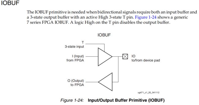
不管哪种方式实现IO功能,从编译结果看都会调用IOBUF原语,为此,我们先来看一下IOBUF的结构,如下图所示。
1.FPGA原语实现
首先,我们编写的代码如下:
 1`define PRIMITIVE
 2
 3 module io_buf(
 4     input    T    ,
 5     input    I    ,
 6     output    O    ,
 7     inout    IO
 8 );
 9
10 `ifdef PRIMITIVE
11     IOBUF #(
12         .DRIVE            (12            ),    // Specify the output drive strength
13         .IBUF_LOW_PWR    ("TRUE"        ),    // Low Power - "TRUE", High Performance = "FALSE"
14         .IOSTANDARD        ("DEFAULT"    ),    // Specify the I/O standard
15         .SLEW            ("SLOW"        )    // Specify the output slew rate
16     ) IOBUF_INST (
17         .O                (O            ),    // Buffer output
18         .IO                (IO            ),    // Buffer inout port (connect directly to top-level port)
19         .I                (I            ),    // Buffer input
20         .T                (T            )    // 3-state enable input, high=input, low=output
21     );
22 `else
23     assign IO = T? I:1'bz;
24     assign O  = IO;
25 `endif
26
27 endmodule
该代码通过原语IOBUF实现IO功能,使用Vivado编译后的原理图如下图所示。可以看到IOBUF内部由OBUFT和IBUF原语构成。
2.使用Verilog实现
把`define PRIMITIVE注释掉,则为通过Verilog的实现方式,如下图:
//`define PRIMITIVE

module io_iobuf(
    input    T    ,
    input    I    ,
    output    O    ,
    inout    IO
);

`ifdef PRIMITIVE
    IOBUF #(
        .DRIVE            (12            ),    // Specify the output drive strength
        .IBUF_LOW_PWR    ("TRUE"        ),    // Low Power - "TRUE", High Performance = "FALSE"
        .IOSTANDARD        ("DEFAULT"    ),    // Specify the I/O standard
        .SLEW            ("SLOW"        )    // Specify the output slew rate
    ) IOBUF_INST (
        .O                (O            ),    // Buffer output
        .IO                (IO            ),    // Buffer inout port (connect directly to top-level port)
        .I                (I            ),    // Buffer input
        .T                (T            )    // 3-state enable input, high=input, low=output
    );
`else
    assign IO = T? I:1'bz;
    assign O  = IO;
`endif

endmodule
该代码使用Vivado编译后的原理图如下图所示。该实现方式也会调用IOBUF原语,但多消耗了一个LUT资源。
通过Verilog实现时,我们在把IO信号当成输入时给赋值高阻态(1‘bz)。假如我们把此时的IO信号赋值1‘b0或者1‘b1,会出现什么情况呢?我们把1‘bz写成1‘b1,如下所示:
 1 //`define PRIMITIVE
 2
 3 module io_iobuf(
 4     input    T    ,
 5     input    I    ,
 6     output    O    ,
 7     inout    IO
 8 );
 9
10 `ifdef PRIMITIVE
11     IOBUF #(
12         .DRIVE            (12            ),    // Specify the output drive strength
13         .IBUF_LOW_PWR    ("TRUE"        ),    // Low Power - "TRUE", High Performance = "FALSE"
14         .IOSTANDARD        ("DEFAULT"    ),    // Specify the I/O standard
15         .SLEW            ("SLOW"        )    // Specify the output slew rate
16     ) IOBUF_INST (
17         .O                (O            ),    // Buffer output
18         .IO                (IO            ),    // Buffer inout port (connect directly to top-level port)
19         .I                (I            ),    // Buffer input
20         .T                (T            )    // 3-state enable input, high=input, low=output
21     );
22 `else
23     assign IO = T? I:1'b1;
24     assign O  = IO;
25 `endif
26
27 endmodule
编译后的原理图如下,可以看到并不会调用IOBUF原语,IO的不能实现输入功能,这就是解释了为什么在使用Verilog实现一根信号的IO功能时需要赋值1‘bz。


