基于LVDS电平标准的Cameralink传输()
一.应用情景概述
在以往的Cameralink相机采集中,通常会有协议解码芯片,但如今,在不使用解码芯片的情况下,直接由相机直接用Cameralink标准协议过LVDS直接把数据传输至FPGA。
二.协议介绍
一根时钟线,其余四根为数据线。均采用差分方式LVDS标准输出至FPGA。
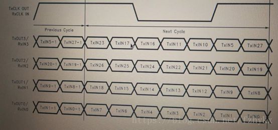
时钟频率固定为25MHZ并不是(175MHZ),每7个数据共用一个时钟周期。具体数据位如图所示:
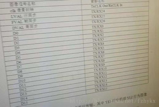
点号定义如下:
三.解码方式
由于没有解码芯片,所以需要在FPGA模块设计时,在采集模块之前设计一个并转串的模块。区分出行场同步信号以及数据信号即一个时钟对应相应的数据位和相应的同步信号。以下为解码部分的具体实现。
1>差分信号变单端信号:
由于是5对LVDS差分信号对直接与FPGA直接相连,因此需要使用原语(xilinx K7)将差分信号转化为单端信号。
IBUFDS #(
.DIFF_TERM("true"), // Differential Termination
.IBUF_LOW_PWR("FALSE"), // Low power="TRUE", Highest performance="FALSE"
.IOSTANDARD("LVDS") // Specify the input I/O standard
) IBUFDS_inst0 (
.O(data_in_to_device[0]), // Buffer output
.I(data_in_from_pins_p[0]), // Diff_p buffer input (connect directly to top-level port)
.IB(data_in_from_pins_n[0]) // Diff_n buffer input (connect directly to top-level port)
);
IBUFDS #(
.DIFF_TERM("true"), // Differential Termination
.IBUF_LOW_PWR("FALSE"), // Low power="TRUE", Highest performance="FALSE"
.IOSTANDARD("LVDS") // Specify the input I/O standard
) IBUFDS_inst1 (
.O(data_in_to_device[1]), // Buffer output
.I(data_in_from_pins_p[1]), // Diff_p buffer input (connect directly to top-level port)
.IB(data_in_from_pins_n[1]) // Diff_n buffer input (connect directly to top-level port)
);
IBUFDS #(
.DIFF_TERM("true"), // Differential Termination
.IBUF_LOW_PWR("FALSE"), // Low power="TRUE", Highest performance="FALSE"
.IOSTANDARD("LVDS") // Specify the input I/O standard
) IBUFDS_inst2 (
.O(data_in_to_device[2]), // Buffer output
.I(data_in_from_pins_p[2]), // Diff_p buffer input (connect directly to top-level port)
.IB(data_in_from_pins_n[2]) // Diff_n buffer input (connect directly to top-level port)
);
IBUFDS #(
.DIFF_TERM("true"), // Differential Termination
.IBUF_LOW_PWR("FALSE"), // Low power="TRUE", Highest performance="FALSE"
.IOSTANDARD("LVDS") // Specify the input I/O standard
) IBUFDS_inst3 (
.O(data_in_to_device[3]), // Buffer output
.I(data_in_from_pins_p[3]), // Diff_p buffer input (connect directly to top-level port)
.IB(data_in_from_pins_n[3]) // Diff_n buffer input (connect directly to top-level port)
);
IBUFDS #(
.DIFF_TERM("true"), // Differential Termination
.IBUF_LOW_PWR("FALSE"), // Low power="TRUE", Highest performance="FALSE"
.IOSTANDARD("LVDS") // Specify the input I/O standard
) IBUFDS_inst4 (
.O(clk_out), // Buffer output
.I(clk_in_p), // Diff_p buffer input (connect directly to top-level port)
.IB(clk_in_n) // Diff_n buffer input (connect directly to top-level port)
);
由此就变成了五根单端信号线,然后再对这五根信号线进行操作。
2>串转并
再看一遍时序图:
五根单端信号如上图所示,由于7个bit公用一个时钟,所以我们要用175M= 25M*7 的时钟来采集25M时钟线的上升沿。具体verliog代码如下:
always @(posedge inClk175M)
begin
if(~inRstn)begin
regState <= cIDLE;
regFifo_Din28 <= 0;
regRiseCnt16 <= 0;
end else begin
case(regState)
cIDLE:begin
if(regClkSyncRise[1]==1)begin
regRiseCnt16 <= regRiseCnt16 + 1;
regFifo_Din28[23] <= regDataSync[3];
regFifo_Din28[26] <= regDataSync[2];
regFifo_Din28[18] <= regDataSync[1];
regFifo_Din28[7] <= regDataSync[0];
if(regRiseCnt16==16'hFFFF)
regState <= cS1;
end
end
cS1:begin
regFifo_Din28[17] <= regDataSync[3];
regFifo_Din28[25] <= regDataSync[2];
regFifo_Din28[15] <= regDataSync[1];
regFifo_Din28[6] <= regDataSync[0];
regState <= cS2;
end
cS2:begin
regFifo_Din28[16] <= regDataSync[3];
regFifo_Din28[24] <= regDataSync[2];
regFifo_Din28[14] <= regDataSync[1];
regFifo_Din28[4] <= regDataSync[0];
regState <= cS3;
end
cS3:begin
regFifo_Din28[11] <= regDataSync[3];
regFifo_Din28[22] <= regDataSync[2];
regFifo_Din28[13] <= regDataSync[1];
regFifo_Din28[3] <= regDataSync[0];
regState <= cS4;
end
cS4:begin
regFifo_Din28[10] <= regDataSync[3];
regFifo_Din28[21] <= regDataSync[2];
regFifo_Din28[12] <= regDataSync[1];
regFifo_Din28[2] <= regDataSync[0];
regState <= cS5;
end
cS5:begin
regFifo_Din28[5] <= regDataSync[3];
regFifo_Din28[20] <= regDataSync[2];
regFifo_Din28[9] <= regDataSync[1];
regFifo_Din28[1] <= regDataSync[0];
regState <= cS6;
end
cS6:begin
regFifo_Din28[27] <= regDataSync[3];
regFifo_Din28[19] <= regDataSync[2];
regFifo_Din28[8] <= regDataSync[1];
regFifo_Din28[0] <= regDataSync[0];
regState <= cS7;
regFifo_WrEn <= 1;
end
cS7:begin
regFifo_Din28[23] <= regDataSync[3];
regFifo_Din28[26] <= regDataSync[2];
regFifo_Din28[18] <= regDataSync[1];
regFifo_Din28[7] <= regDataSync[0];
regFifo_WrEn <= 0;
regState <= cS1;
end
endcase
end
end
由于有跨时钟域操作,因此需要将这些数据写入异步FIFO。在判断好第一个上升沿之后,将数据每七个时钟(175M)写入一次,采集到一次上升沿之后一直循环不再判断25M的上升沿。

