数据中心网络搭建
网络搭建
前言
随着互联网应用的深入,人们对互联网的依赖也越来越重:对于互联网公司而言,如果因为故障导致用户无法使用Web服务,那么每一分钟的经济损失都会让公司难以承受;如果员工无法访问工作用途的Web应用程序,那么工作效率也随之大大下降……
冗余性是一条基准的IT准则。无论是运行同一Web应用程序的多台后端服务器,还是构建组成RAID阵列的磁盘驱动器,IT部门都要定期确保可用性,即便在出现故障的情况下也是如此。
为了保持网络的稳定性,在多台交换机组成的网络环境中,通常都使用一些备份连接,以提高网络的健壮性、稳定性,这里的备份连接也称为备份链路或者冗余链路。
在骨干网设备连接中,单一链路的连接很容易实现,但一个简单的故障就会造成网络的中断.因此在实际网络组建的过程中,为了保持网络的稳定性,在多台交换机组成的网络环境中,通常都使用一些备份连接,以提高网络的健壮性、稳定性
这里的备份连接也称为备份链路或者冗余链路.备份链路之间的交换机经常互相连接,形成一个环路,通过环路可以在一定程度上实现冗余.
链路的冗余备份能为网络带来健壮性、稳定性和可靠性等好处,但是备份链路也会使网络存在环路,环路问题是备份链路所面临的最为严重的问题,交换机之间的环路将导致网络新问题的发生
一. 冗余设计
1.1原网络模型:
目标是为了实现核心网络交换的负载均衡、互为备份、冗余等功能,先规划好物理架构,再逐步添加设备。在满足现有网络需求的同时,考虑未来发展,为未来可预期的风险提供保障。下图为前期简单的网络拓扑。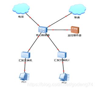
1.2现状分析:
目前架构模式采用单台华为防火墙6306作为出口网关设备,兼顾内网安全,外部采用双链路ospf路由,一条电信,一条移动,当一条链路故障时,可切换到另外一条线路继续使用。下连华为交换机S5700,作为核心交换机,各服务器直连核心交换机以减少故障率,内网划分虚拟网络,使各部门及楼层逻辑隔离,当某部门或楼层被攻击、网络风暴等情况不会影响其他部门网络使用。
虽然现有网络能满足部分安全需求,但从图中不难看出,单点故障随时可能出现,当核心交换机、防火墙和防火墙与核心交换机之间的链路故障时,那么网络将陷于瘫痪之中,整个网络都不能访问。而且设备维修周期和新设备的采购周期较长,不能及时恢复网络使用。
新拓扑模型:
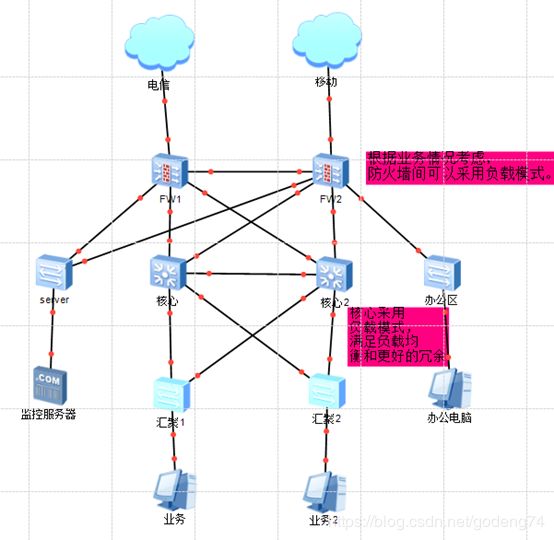
1.3新拓扑的特点:
拓扑的布局新特点:
1、 考虑防火墙防御模块授权和硬盘采购成本较高,网络现状单台负担完全足够,所以防火墙采用主备模式,后面也可以采用负载模式。配置信息实时同步,及当主设备出现故障时或宕机,及时将外部线路连接到另一台设备上,以达到网络的不受任何影响。
2、 核心交换机采用负载模式,也就是两台核心都在同时跑业务,当一台设备故障时,另一台也能实时接替所有工作,以达到冗余。
3、 所有线路都采用双线,分别连接两台核心交换机,包括服务器,以达到带宽叠加和线路冗余效果,及当无故障时,传输速度提升一倍,当其中一条或者其中一台核心交换机故障时,另一条继续工作,不会产生断网现象。
二. 网络需求分析
- 到实地现场勘察,确定是否考略网络完全做处想应措施,比如独立机房,三网隔离,组网隔离等。
2.勘察生产环境现场,使用的设备的数量。其中包括接入层的傻瓜交换机,汇聚层的汇聚交换机以及核心层用到的核心交换机。其中在确认核心和汇聚交换机的时候,确认好核心到汇聚走的是光信号还是电信号。值得注意的是,当用光信号时,我们的核心需要采购全光口的设备。
3.设计到光模块的选购,市面上大多设备用到的光模块为LC-SPF俗称小方头光模块,使用比较稳定。也有用大方头和圆头的光模块,属于定制,市面较难采购。采购光模块时还需考虑单模和多模之分。
4.网线以及光纤跳线法兰的采购。采购跳纤时需根据光模块信号采购。可以考虑采购光收发,以便不时之需。
5.光纤入户的带宽根据业务需求考虑多大带宽合适。
6.假设的网络还需考虑到网络延迟与可预测响应时间, 可靠性/可用性。即系统(包含路由器、核心层交换机、汇聚层交换机等设备)不停机运行,伸缩性。网络系统能否适应用户不断增长的需求,高安全性。保护用户信息和物理资源的完整性,包括数据备份、灾难恢复等。概括起来,系统分析员对网络用户方调查可通过填写调查表来完成。
三. 网络搭建交换机配置
在配置前根据网络需求提前规划好ip
3.1防火墙网络配置
(1)先配置防火墙,根据网络划分情况在防火墙上划分不同的安全区域以及优先级。,

(2)根据接口将不同的接口划至不同的安全区域并配好ip地址。
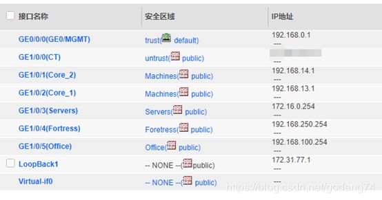
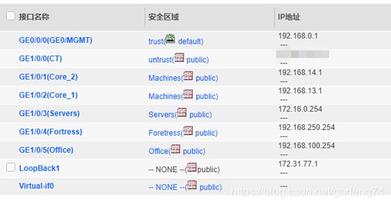
(3)根据ip配置路由,考虑做网络冗余于是采用ospf路由,部分设备型号不支持ospf只能使用静态路由并引入到ospf中如图。


在发布ospf中发布静态路由时需要过滤。
route-policy ospf-import permit node 10
if-match ip-prefix mms
#ip ip-prefix mms index 10 permit 10.0.1.10 32
配置静态路由
#ip route-static 10.0.1.0 255.255.255.0 172.16.0.1
#ip route-static 10.0.1.10 255.255.255.255 172.16.0.1
#ip route-static 192.168.252.0 255.255.255.0 192.168.250.1
发布到osps中
ospf 100 router-id 1.1.1.1
default-route-advertise
import-route static route-policy ospf-import
配置opsf路由
#
ospf 100 router-id 1.1.1.1
area 0.0.0.0
network 172.16.0.254 0.0.0.0
network 172.31.77.1 0.0.0.0
network 192.168.13.1 0.0.0.0
network 192.168.14.1 0.0.0.0
network 192.168.100.254 0.0.0.0
network 192.168.252.254 0.0.0.0
#
(4)配置默认路由出外网ip带ip—link检测
先配置nqa
nqa test-instance ISP CT
test-type icmp
destination-address ipv4 36.108.184.1
frequency 3
interval seconds 1
timeout 1
probe-count 2
source-interface GigabitEthernet1/0/0
start now
#
再配置默认路由并在ospf中发布默认路由
ip route-static 0.0.0.0 0.0.0.0 36.108.184.1 track nqa ISP CT description CT
ospf 100 router-id 1.1.1.1
default-route-advertise
spf-schedule-interval millisecond 5000
(5)配置dhcp dns
dns resolve
dns server 114.114.114.114
dns server 223.5.5.5
dhcp enable
(6)接口地址ip规划好后配置nat,根据划分好的的安全区域来配置如图:

(7)防火墙1的安全策略需要暂时放开全为any后面一点一点收敛。以便测试调试需要。

(8)建立用户名以及权限访问方式等
manager-user gaopan
password cipher @%@%E8:’".=UTPSJXNO]OYa’N]8V&#K:+xH91Hzk=UQ}saCA]8
service-type web terminal telnet ssh
level 15
*user-interface con 0
authentication-mode password
set authentication password cipher 1 c 1c 1clei,5dkb%5$n#z-ARj(8D;/1
user-interface vty 0 4
authentication-mode aaa
protocol inbound ssh
user-interface vty 16 20
(9)根据需求配置对象,地址组和域名组
(10) 防火墙1的配置初步完成。防火墙2和防火墙1的配置类似相同。根据内网不同的需求,可将下面的局域网挂在不同的防火墙下,例如核心交换机下的网络保障较高可以同时挂在两个防火墙上,而办公网的安全保证较低可以挂靠在一个防火墙下。这样可减少防火墙的负担,合理的利用网络资源。值得注意的是在不同型号的交换机挂在防火墙上可能采用的路由方式也不同,有的不支持ospf 需要在防火墙上写好回指路由发布到ospf中。防火墙上的接口如果够多的话,需要将两个防火墙也链接起来,配置好ip并发布到ospf中。
3.2核心层网络配置:
3.2.1配置core1
(1)先配置core1 根据内网需求划分好ip段。核心到汇聚的ip段划分如下:
Core_1_G0/0/1 172.31.101.1 对端地址 汇聚1-1 172.31.101.2
Core_1_G0/0/2 172.31.102.1 汇聚1-2 172.31.102.2
Core_1_G0/0/3 172.31.103.1 汇聚1-3 172.31.103.2
Core_1_G0/0/4 172.31.104.1 汇聚1-4 172.31.104.2
Core_1_G0/0/5 172.31.105.1 汇聚2-1 172.31.105.2
Core_1_G0/0/6 172.31.106.1 汇聚2-2 172.31.106.2
Core_1_G0/0/7 172.31.107.1 汇聚3-1 172.31.107.2
Core_1_G0/0/8 172.31.108.1 汇聚3-2 172.31.108.2
(2)core1全局模式下配置dhcp dns
dhcp enable
dns resolve
dns server 114.114.114.114
dns server 223.5.5.5
(3)开通接口隔离功能
#port-isolate mode all
(4)配置接口ip并划分接口隔离group,使之每个接口间都不能互相访问,这样做对下面的局域网提高安全保证。
#interface GigabitEthernet0/0/1
undo portswitch
description SW1-1
ip address 172.31.101.1 255.255.255.0
port-isolate enable group 1
#interface GigabitEthernet0/0/2
undo portswitch
description SW1-2
ip address 172.31.102.1 255.255.255.0
port-isolate enable group 1
#interface GigabitEthernet0/0/3
undo portswitch
description SW1-3
ip address 172.31.103.1 255.255.255.0
port-isolate enable group 1
#interface GigabitEthernet0/0/4
undo portswitch
description SW1-4
ip address 172.31.104.1 255.255.255.0
port-isolate enable group 1
#interface GigabitEthernet0/0/5
undo portswitch
description SW2-1
ip address 172.31.105.1 255.255.255.0
port-isolate enable group 1
#interface GigabitEthernet0/0/6
undo portswitch
description SW2-2
ip address 172.31.106.1 255.255.255.0
port-isolate enable group 1
#interface GigabitEthernet0/0/7
undo portswitch
description SW3-1
ip address 172.31.107.1 255.255.255.0
port-isolate enable group 1
#interface GigabitEthernet0/0/8
undo portswitch
description SW3-2
ip address 172.31.108.1 255.255.255.0
port-isolate enable group 1
(5)配置两个核心间的互联口和上联口ip 其中26口为连接core2使用,27口为连接防火墙1使用,28口为连接防火墙2使用。
#interface GigabitEthernet0/0/26
undo portswitch
ip address 192.168.34.3 255.255.255.0
#interface GigabitEthernet0/0/27
undo portswitch
description to FW1
ip address 192.168.13.3 255.255.255.0
#interface GigabitEthernet0/0/28
undo portswitch
description to FW2
ip address 192.168.23.3 255.255.255.0
(6)建立ospf并发布接口网段
#ospf 100 router-id 3.3.3.3
area 0.0.0.0
network 10.1.1.254 0.0.0.0
network 172.31.34.3 0.0.0.0
network 172.31.77.3 0.0.0.0
network 172.31.101.1 0.0.0.0
network 172.31.102.1 0.0.0.0
network 172.31.103.1 0.0.0.0
network 172.31.104.1 0.0.0.0
network 172.31.105.1 0.0.0.0
network 172.31.106.1 0.0.0.0
network 172.31.107.1 0.0.0.0
network 172.31.108.1 0.0.0.0
network 192.168.13.3 0.0.0.0
network 192.168.23.3 0.0.0.0
(7)值得注意下,由于核心下接的汇聚交换机不支持ospf功能,我们需要配置静态路由,在核心上写好回指路由并引入的ospf中。
ip route-static 10.11.0.0 255.255.0.0 172.31.101.2
ip route-static 10.12.0.0 255.255.0.0 172.31.102.2
ip route-static 10.13.0.0 255.255.0.0 172.31.103.2
ip route-static 10.14.0.0 255.255.0.0 172.31.104.2
ip route-static 10.21.0.0 255.255.0.0 172.31.105.2
ip route-static 10.22.0.0 255.255.0.0 172.31.106.2
ip route-static 10.31.0.0 255.255.0.0 172.31.107.2
ip route-static 10.32.0.0 255.255.0.0 172.31.108.2
引入到ospf中
ospf 100 router-id 3.3.3.3
import-route static
(8)建立账号配置登录方式 并打开相应登录的服务
local-user gaopan password irreversible-cipher 1 a 1a 1a|w9
local-user gaopan privilege level 15
local-user gaopan service-type telnet terminal ssh http
#
user-interface con 0
authentication-mode password
set authentication password cipher 1 c 1c 1c&hmK
user-interface vty 0 4
authentication-mode aaa
protocol inbound all
user-interface vty 16 20
#telnet server enable
3.3汇聚层交换机配置
货架 1货架 2货架 3货架
ip 10.11.1.0 10.11.2.0 10.11.3.0
vlan 101 102 103
(2)配置dhcp dns vlan 开通接口隔离功能
#dns resolve
#dns server 114.114.114.114
#vlan batch 100 to 110 1000 2000
#dhcp enable
#port-isolate mode all
(3)vlan配置ip
#interface Vlanif101
ip address 10.11.1.254 255.255.255.0
dhcp select interface
dhcp server dns-list 114.114.114.114 223.5.5.5
#interface Vlanif102
ip address 10.11.2.254 255.255.255.0
dhcp select interface
dhcp server dns-list 114.114.114.114 223.5.5.5
#interface Vlanif103
ip address 10.11.3.254 255.255.255.0
dhcp select interface
dhcp server dns-list 114.114.114.114 223.5.5.5
#interface Vlanif104
ip address 10.11.4.254 255.255.255.0
dhcp select interface
dhcp server dns-list 114.114.114.114 223.5.5.5
#interface Vlanif105
ip address 10.11.5.254 255.255.255.0
dhcp select interface
dhcp server dns-list 114.114.114.114 223.5.5.5
#interface Vlanif106
ip address 10.11.6.254 255.255.255.0
dhcp select interface
dhcp server dns-list 114.114.114.114 223.5.5.5
#interface Vlanif107
ip address 10.11.7.254 255.255.255.0
dhcp select interface
dhcp server dns-list 114.114.114.114 223.5.5.5
#interface Vlanif108
ip address 10.11.8.254 255.255.255.0
dhcp select interface
dhcp server dns-list 114.114.114.114 223.5.5.5
#interface Vlanif109
ip address 10.11.9.254 255.255.255.0
dhcp select interface
dhcp server dns-list 114.114.114.114 223.5.5.5
#interface Vlanif110
ip address 10.11.10.254 255.255.255.0
dhcp select interface
dhcp server dns-list 114.114.114.114 223.5.5.5
(4)配置上联口vlan ip
#interface Vlanif1000
ip address 172.31.101.2 255.255.255.0
#interface Vlanif2000
ip address 172.31.201.2 255.255.255.0
(5)把接口划分到vlan下并划分接口隔离group
#interface Ethernet0/0/1
port link-type access
port default vlan 101
port-isolate enable group 1
#interface Ethernet0/0/2
port link-type access
port default vlan 102
port-isolate enable group 1
#interface Ethernet0/0/3
port link-type access
port default vlan 103
port-isolate enable group 1
#interface Ethernet0/0/4
port link-type access
port default vlan 104
port-isolate enable group 1
#interface Ethernet0/0/5
port link-type access
port default vlan 105
port-isolate enable group 1
#interface Ethernet0/0/6
port link-type access
port default vlan 106
port-isolate enable group 1
#interface Ethernet0/0/7
port link-type access
port default vlan 107
port-isolate enable group 1
#interface Ethernet0/0/8
port link-type access
port default vlan 108
port-isolate enable group 1
#interface Ethernet0/0/9
port link-type access
port default vlan 109
port-isolate enable group 1
#interface Ethernet0/0/10
port link-type access
port default vlan 110
port-isolate enable group 1
#interface GigabitEthernet0/0/3
port link-type access
port default vlan 1000
#interface GigabitEthernet0/0/4
port link-type access
port default vlan 2000
(6)配置默认路由,备用路由优先级为70
#ip route-static 0.0.0.0 0.0.0.0 172.31.101.1
#ip route-static 0.0.0.0 0.0.0.0 172.31.201.1 preference 70
(7)建立账号以及登录方式
#local-user gaopan password cipher %@%@eWEP7^UIgD 22 c 22c 22cb+=;Fo3\E%@%@
local-user gaopan privilege level 15
local-user gaopan service-type telnet terminal ssh web http
#user-interface con 0
authentication-mode password
user privilege level 15
set authentication password cipher %@%@/[+r@q
user-interface vty 0 4
authentication-mode aaa
protocol inbound all
3.4 完成配置重启经常
1.防火墙到汇聚层配置完成,需在核心和防火墙处重启ospf进程,以便ospf学习到邻居。
3.5 其它交换机配置
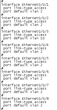
office server foretress交换机配置方式跟汇聚类似,需提前规划好ip网段,根据需要的ip网段来划分不同的vlan,然后在防火墙中需写好回指路由。

将接口划分至vlan中如下图:
四.验证配置是否正确
4.1验证防火墙配置是否正确
在防火墙上ping 114.114.114.114 和下面交换机的管理地址是否通畅
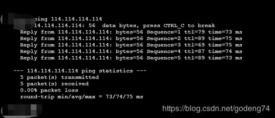
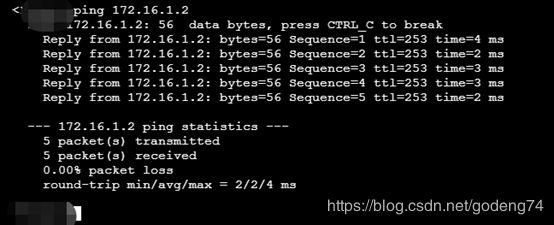
验证完全后待表防火墙出外网没有问题,到下面的汇聚交换机也没有问题
4.2验证汇聚交换机
访问外网是否正常,访问运营商网关是否正常

4.3汇聚下接电脑验证
查看分配ip是否正确,是否可以正常上网。访问其它网段主机是否正常。
4.4跨网段跨安全区访问
1.可以在不同的交换机下试试夸网段访问是否正常,前提是要访问的网段与本网段不在同一隔离group下
2.可以跨防火墙安全区互访验证,前提是在防火墙上还未做策略收敛
五.设备安装
5.1网络设备布置
在机柜上安装交换机时需要考虑每个交换机的间隙散热的问题,带有风扇的交换机尽量设备间隙大些。每个设备上需要打好标签,标好地址,固定好螺母,安好耳朵,设备需接地线。
5.2 网线光纤布置
布置网线时在每个接头处需打好标签,走线整洁,并用轧带固定好。跳纤时选择距离够用的跳纤,不用盘留光纤。需要考虑最后在布置完线后盒上机柜门,不碰电线,网线光纤等。
5.3 电源线布置
布置电线时,需考虑PDU插孔数是否够用,不够需在加PDU插拔,尽量与网络设备保持距离。走线时也需在插头处打好标签,与网线分开走线。同时在插孔出需固定,防止意外拉拽设备掉电。
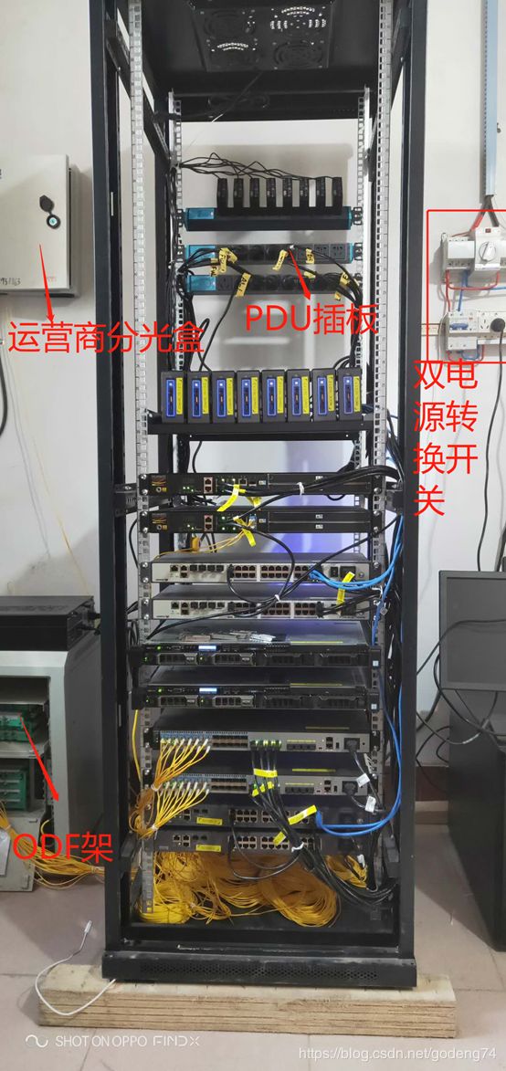
5.4 机柜图
布置完成后封好机柜门
六.机房用的需求
6.1 考虑机房电源是否需要安装双电源转换开关,机房需要使用独立供电。
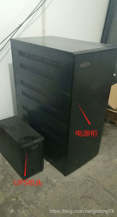
6.2 计算网络设备符合,安装合适的UPS 保证设备不断电
6.3 机柜需要做接地处理,防止网络设备产生静电。
七 设备上电检测是否正常
固定好每个网络设备后,拿电脑在网络最末端,检测网络是否满足设计需求。如有不正常可按照以下几点排查:
1. 检查跳纤,网线顺序是否正常
2. 光纤光强度是否正常,网线是否有弯折或损坏。
3. 检查光纤插入接口是否对应
4. 检查光模块,光收发,法兰等耗材是否有损坏
5. 检查网络配置是否正确。
