电路Circuit->Chapter 13 Three-Phase Circuits(三相电路)
Three-Phase Circuits 三相电路
- 中文部分
- 三相电源
- 三相电路
- 单相交流电动势的产生
- 三相电源
- 三相电路的基本概念
- 三相电路
- 对称三相电路
- 相的概念
- 相线电压电流
- 对称三相电路的线相关系
- 星形联接(Y联接)
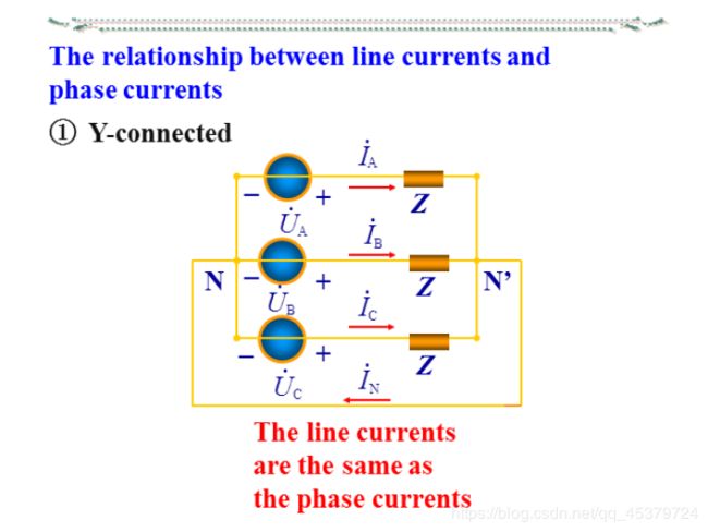
- 线相电流关系(相同)
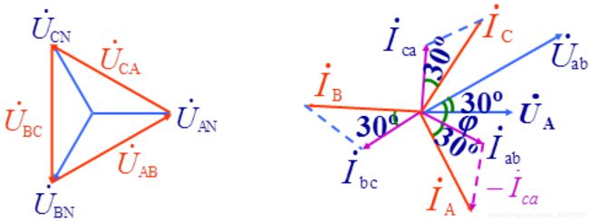
- 线相电压关系(线=√3 超前30°)
- 三角形连接
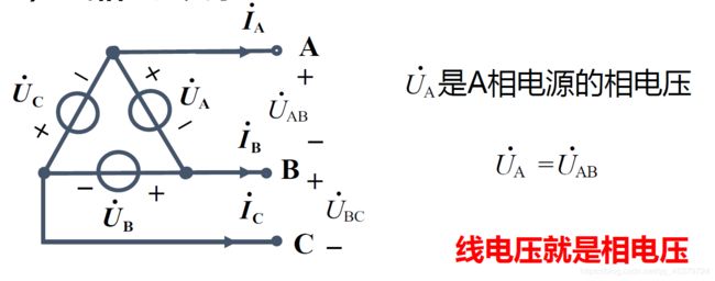
- 线相电压关系(相同)
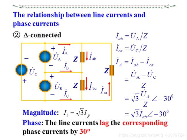
- 线相电流关系(线=√3 滞后30°)
- 对称Y-Y三相电路的计算
- 非Y -Y对称三相电路的计算
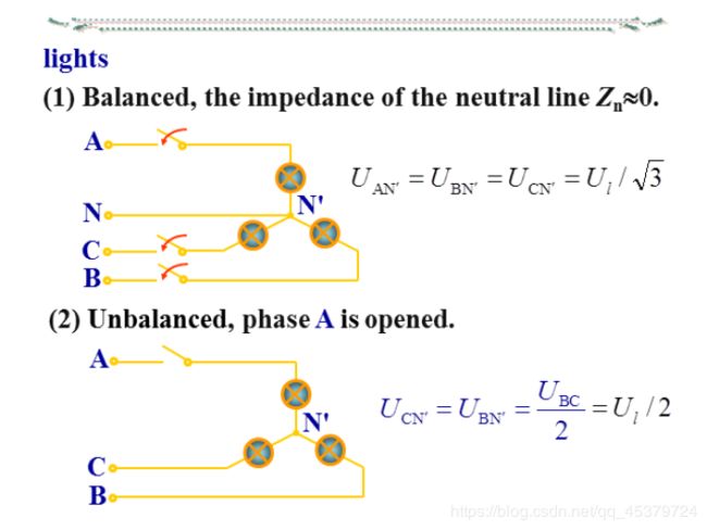
- 三相电路应用举例:简单照明系统及其故障分析
- 三相电路的功率
- 一般三相电路的功率
- 对称三相电路的功率
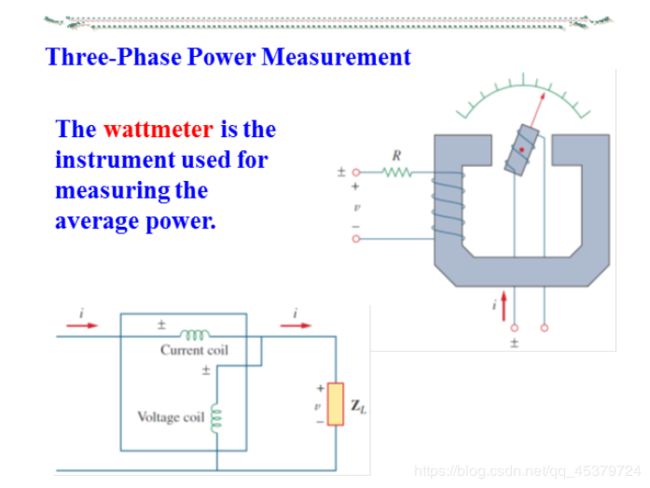
- 三相电路的功率测量
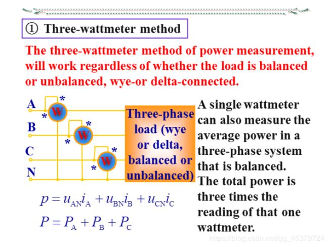
- 三表法(对称,非对称)
- 一表法(对称)
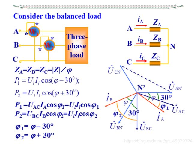
- 二表法(对称,不对称)
- 12.1Introduction
- 12.2 Balanced Three-Phase Voltages
- The generator connections
- The three-phase load and connections
- The relationship between line voltages and phase voltages
- The relationship between line currents and phase currents
- 12.3 Balanced Wye-Wye Connection
- 12.4 Balanced Wye-Delta Connection
- 12.5 Balanced Delta-Delta Connection
- 12.6 Balanced Delta-Wye Connection
- 12.7 Power in a Balanced System
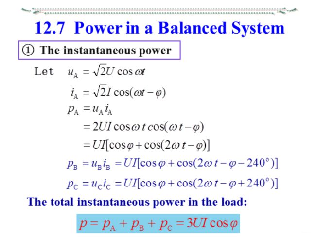
- The instantaneous power(瞬时功率)
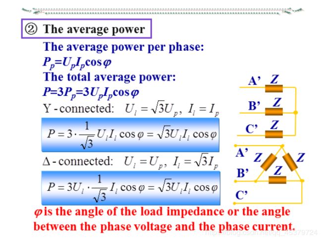
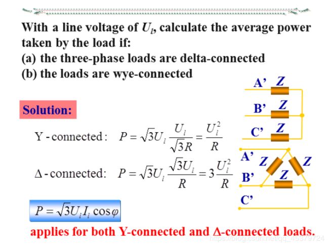
- The average power(平均功率)
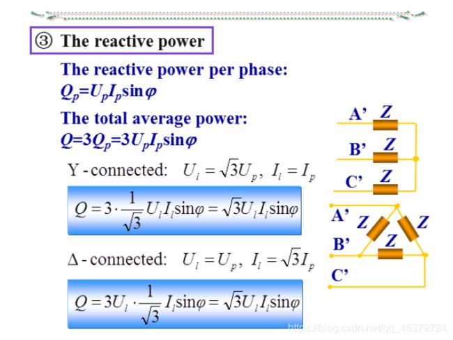
- The reactive power(无功功率)
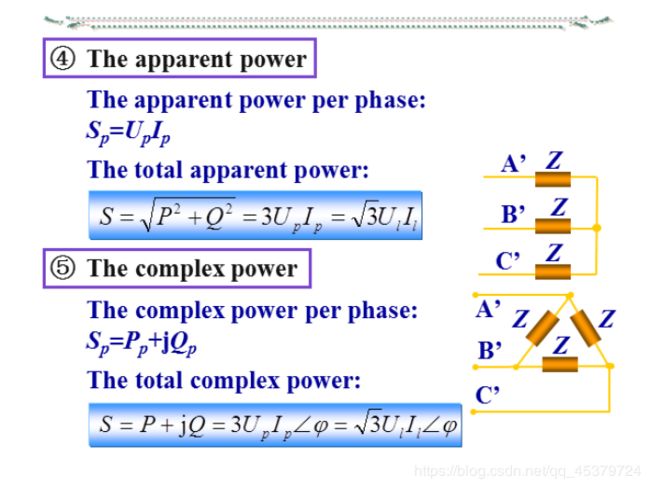
- The apparent power(视在功率) and The complex power(复功率)
- Three-wattmeter method(三表法)
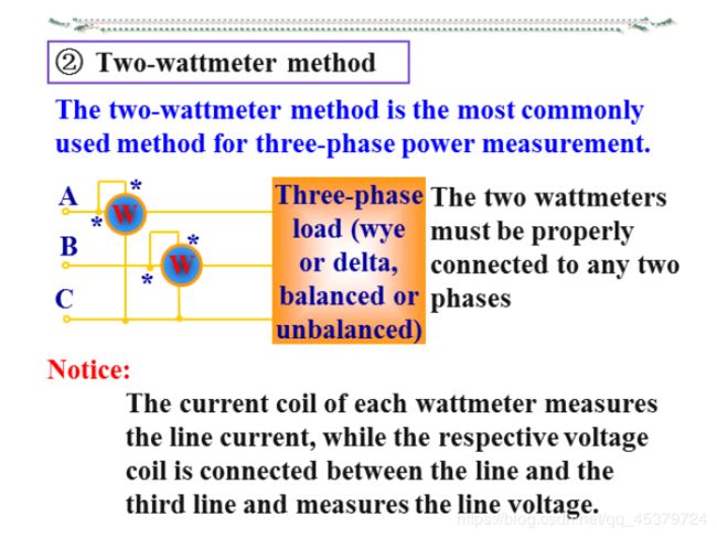
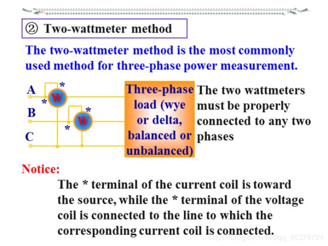
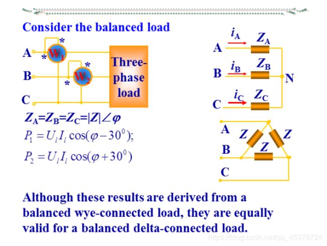
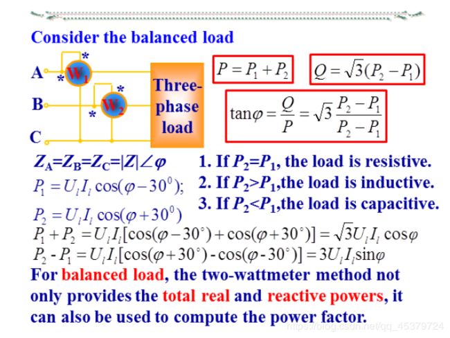
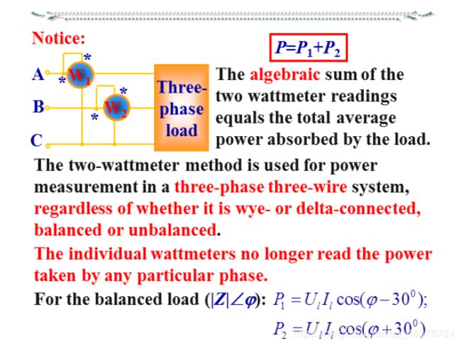
- Two-wattmeter method(两表法,与连接方式无关,)
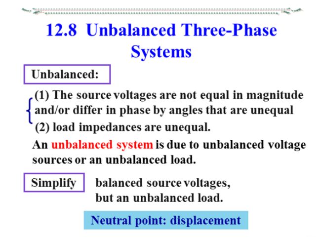
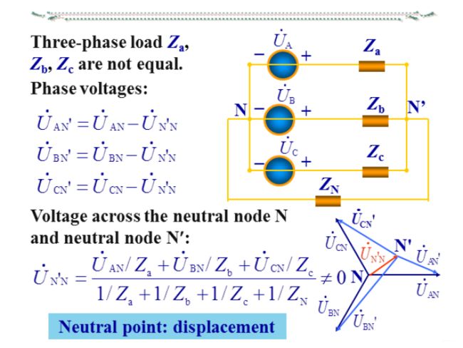
- 12.8 Unbalanced Three-Phase Systems
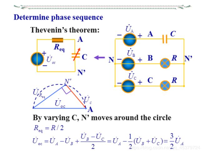
- 相序的判断
中文部分
三相电源
三相电路
由三相电源、三相负载和三相传输线路组成的电路
是一类特殊的正弦稳态电路
应用:发电、输电、配电,以及大功率用电设备等电力系统
目前电力系统采用的主要供电方式
三相电路的优点:
1) 发电:比单相电源可提高功率50%
2) 输电:比单相输电节省钢材25%
3) 配电:三相变压器比单相变压器经济且便于接入负载
4) 用电设备:具有结构简单、成本低、运行可靠、维护方便等优点
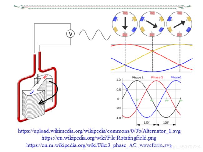
单相交流电动势的产生
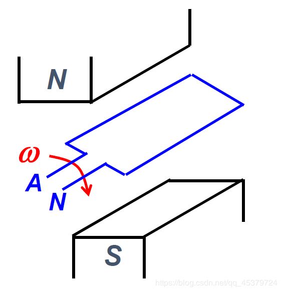
线圈以ω的角速度顺时针旋转
合理设计磁极形状,使磁通按正弦规律分布,便可得到单相交流电动势
u A N = 2 U c o s ω t u_{AN} = \sqrt2Ucosωt uAN=2Ucosωt
三相电源
- 产生
三相绕组在空间互差120°,当转子以角速度ω转动时,在绕组中产生感应电压,从而形成对称三相电源
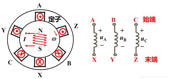
- 表示
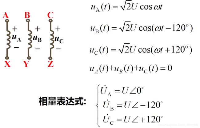
- 相序
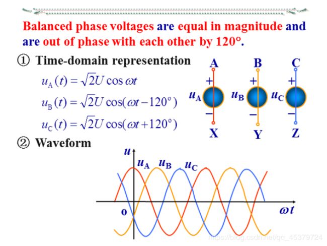
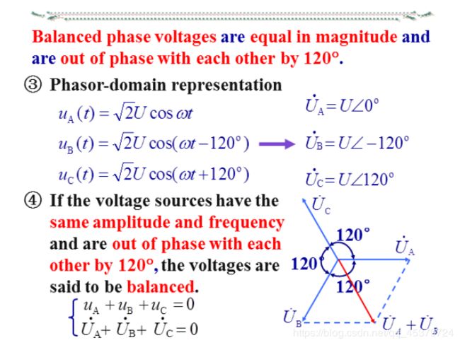
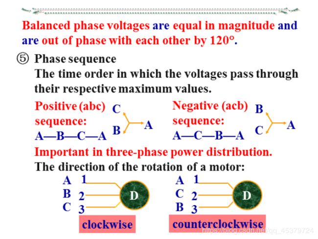
各相电源经过同一值(如最大值)的顺序
正序(顺序):A—B—C—A
负序(逆序):A—C—B—A
相序的意义:对三相电动机,如果相序反了,就会反转
如果不加说明,一般都认为是正相序 - 三相电源的联结
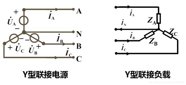
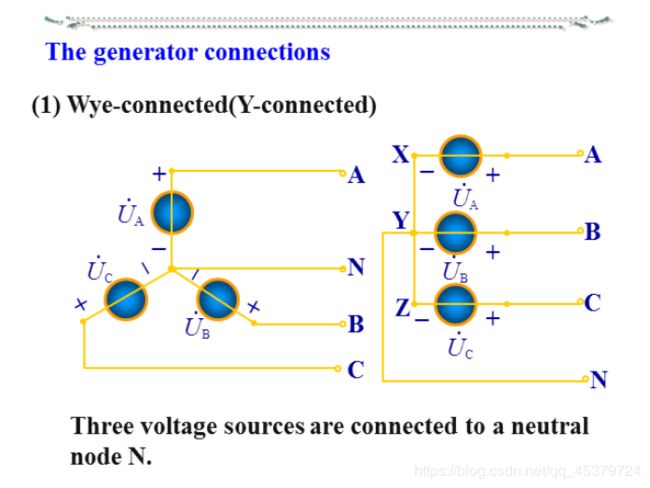
1)星形联接(Y联接)
把三个绕组的末端接在一起
端线(相线、火线):始端引出线ABC
中性线(零线):末端引出线N
在低压系统中,中性点通常接地,也称地线

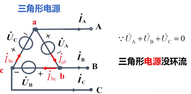
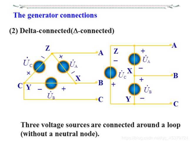
2)三角形联接
把三个绕组首尾相接
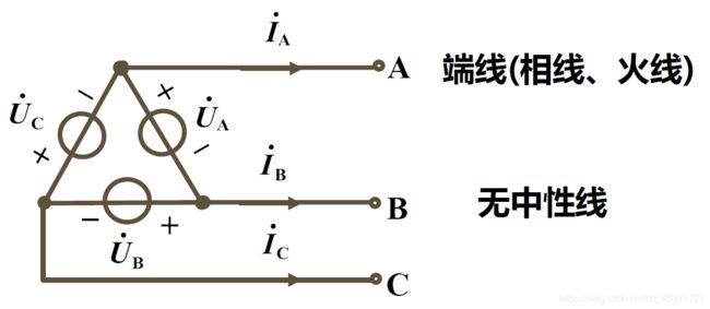
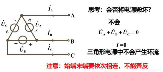
除非接反,才会损坏
三相电路的基本概念
三相电路
对称三相电路
当电源和负载都对称时,称对称三相电路
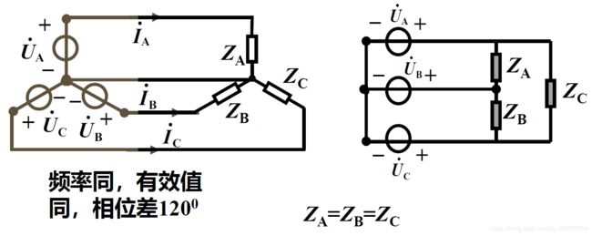
实际三相电路中,不论连接方式如何:
三相电源对称
三条端线传输线的等效阻抗相等
但三相负载不一定对称
相的概念
相线电压电流
相电压:每相电源(负载)的电压
线电压:端线与端线之间的电压
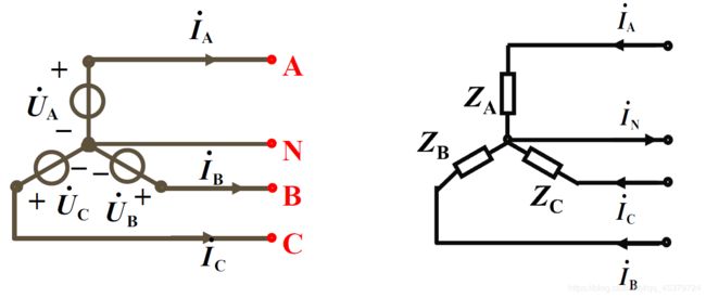
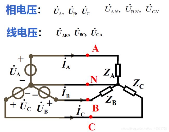
相电流:流过每相电源(负载)的电流
线电流:流过端线的电流
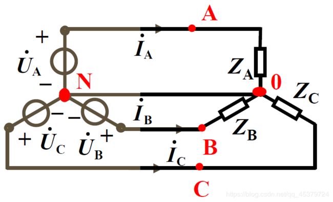
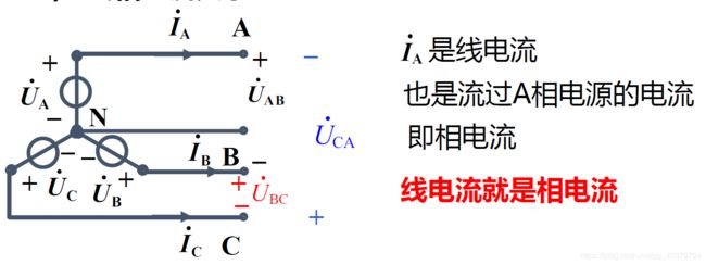
三相四线制,相电流和线电流相同
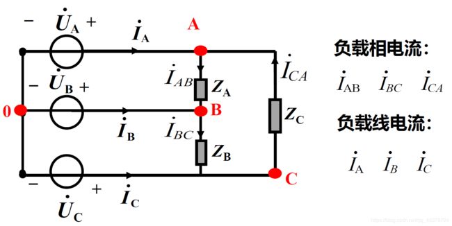
对称三相电路的线相关系
星形联接(Y联接)
线相电流关系(相同)
线相电压关系(线=√3 超前30°)
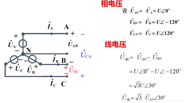
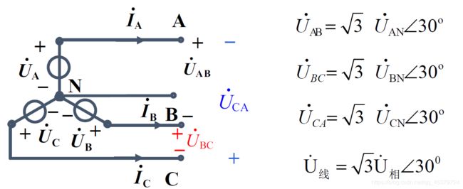
线电压有效值=相电压有效值的√3倍
线电压超前对应相电压30°
“对应”:相电压用线电压的第一个下标字母标出

相电压对称,则线电压也对称
三角形连接
线相电压关系(相同)
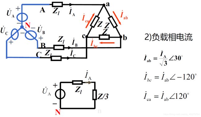
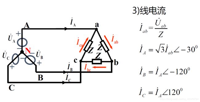
线相电流关系(线=√3 滞后30°)
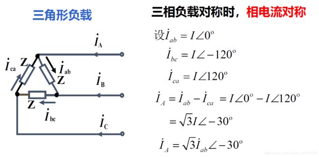
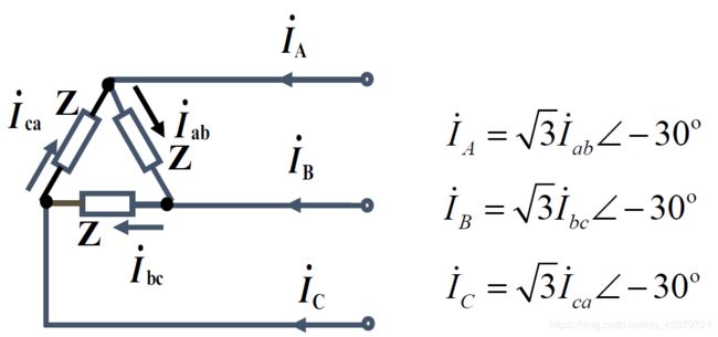
线电流对称
线电流有效值=相电流有效值的√3倍
线电流滞后对应相电流30°
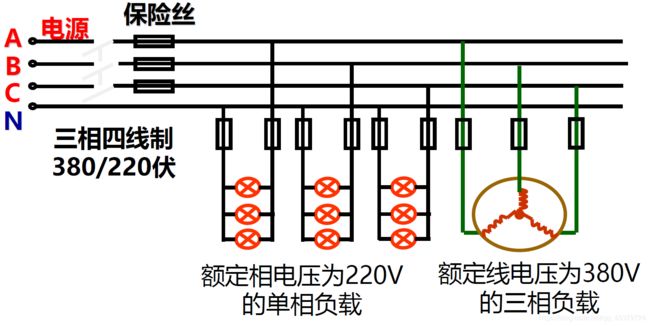
我国供电系统提供三相对称电源采用三相四线制,相电压为220V,线电压为380V,负载接入原则:
1) 电源提供的电压=负载的额定电压
2) 单相负载尽量均衡地分配到三相电源上
三相电动机绕组:可以星形,也可以三角形
照明负载:一般都是星形(具有中性线)
三相负载的联接原则
每相负载上的电压=其额定电压
负载的额定电压 = 电源的线电压 Δ联结
负载的额定电压 = 1 3 \frac{1}{\sqrt {3}} 31电源线电压 Y 联结
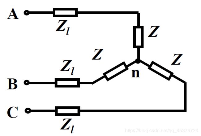
对称Y-Y三相电路的计算
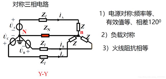
负载对称是指阻抗相等f
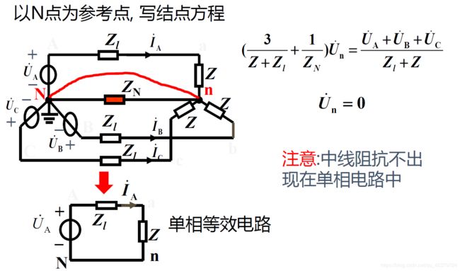
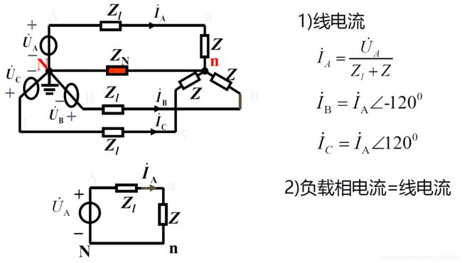
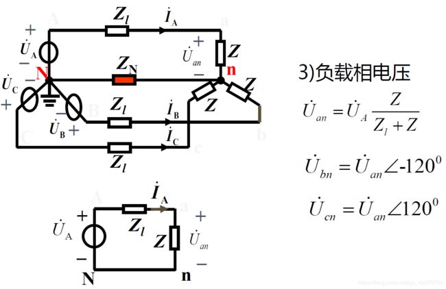
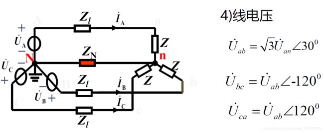
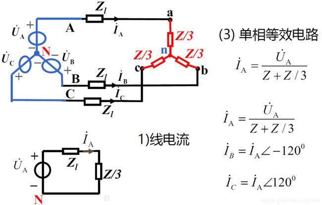
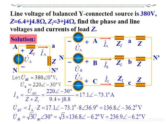
Y -Y接对称三相电路的计算:
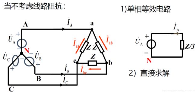
1) 画单相等效电路(一般为A相)
2) 由单相等效电路计算待求的电压、电流
3) 由对称性推出其它二相的电压、电流
非Y -Y对称三相电路的计算
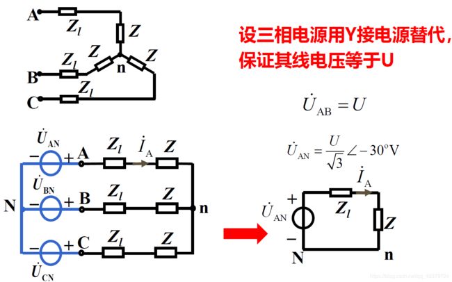
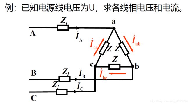
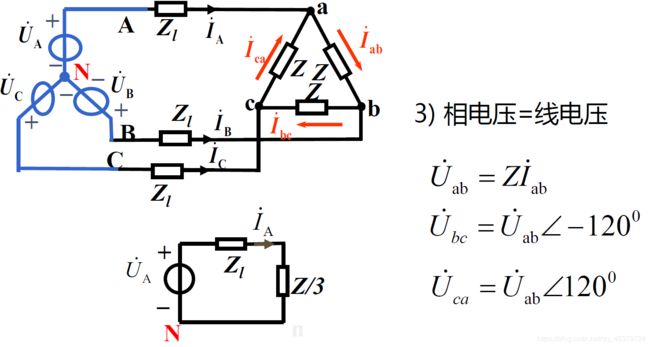
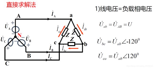
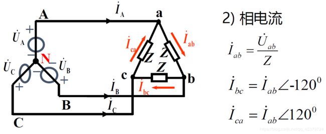
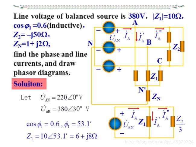
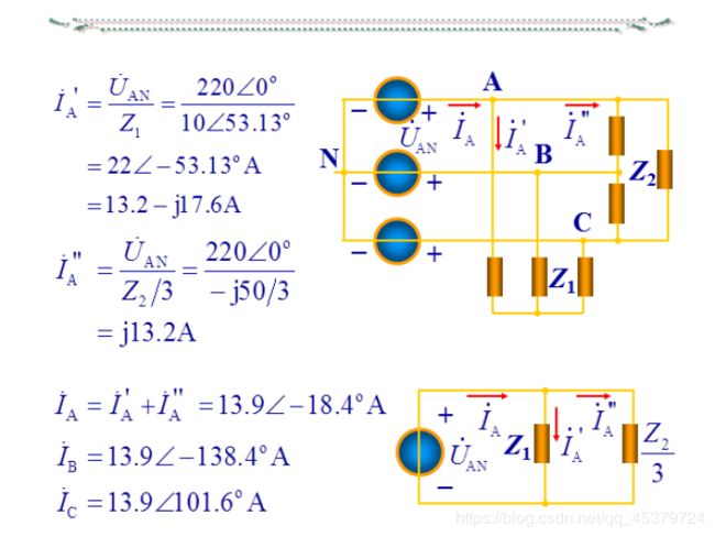
用单相等效电路求解:
1)对三角形连接的对称三相电源:
按线相电压关系进行等效:设三相电 源用Y接电源替代,保证其线电压不变
2)对三角形连接的对称三相负载
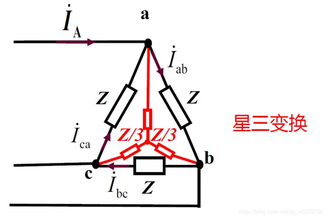
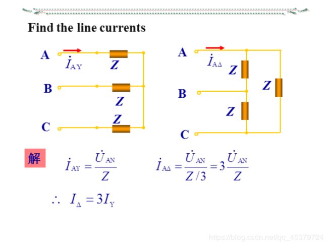
Z Y = 1 3 Z Δ Z_Y=\frac{1}{3}Z_Δ ZY=31ZΔ
一般对称三相电路的计算
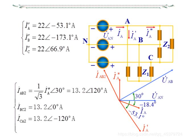
1) 将三相电源、负载都等效看成Y联接;
2) 画出单相等效电路,求出一相的电压、电流;
3) 求解单相等效电路,根据线(相)电压及线(相)电流的关系,求出原电路的电流、电压;(要回到原电路)
4) 由对称性,写出其它两相的电压、电流。
三相电路应用举例:简单照明系统及其故障分析
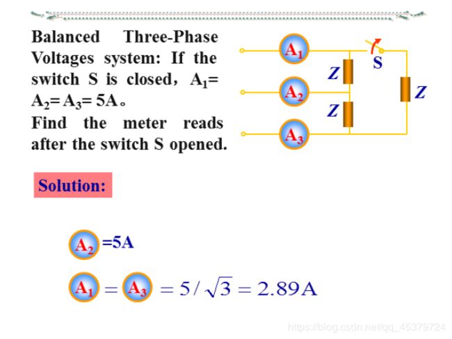
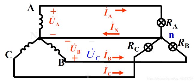
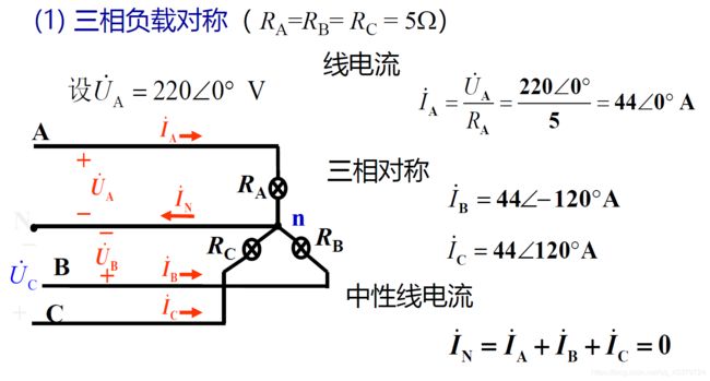
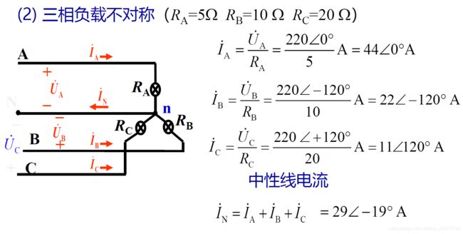
简 单 照 明 系 统 的 线 电 压 为 380 V , 若 灯 泡 R A = R B = R C = 5 Ω ( 1 ) 求 线 电 流 及 中 性 线 电 流 I N ( 2 ) R A = 5 Ω , R B = 10 Ω , R C = 20 Ω , 求 线 电 流 及 I N ( 3 ) A 相 短 路 , 中 性 线 断 开 ( 未 断 ) 时 , 求 负 载 相 电 压 ( 4 ) A 相 断 路 , 中 性 线 断 开 ( 未 断 ) 时 , 求 负 载 相 电 压 简单照明系统的线电压为380V,若灯泡R_A=R_B= R_C = 5Ω\\ (1)求线电流及中性线电流I_N\\ (2)R_A=5Ω,R_B=10Ω,RC=20Ω,求线电流及I_N\\ (3)A相短路,中性线断开(未断)时,求负载相电压\\ (4)A相断路,中性线断开(未断)时,求负载相电压 简单照明系统的线电压为380V,若灯泡RA=RB=RC=5Ω(1)求线电流及中性线电流IN(2)RA=5Ω,RB=10Ω,RC=20Ω,求线电流及IN(3)A相短路,中性线断开(未断)时,求负载相电压(4)A相断路,中性线断开(未断)时,求负载相电压

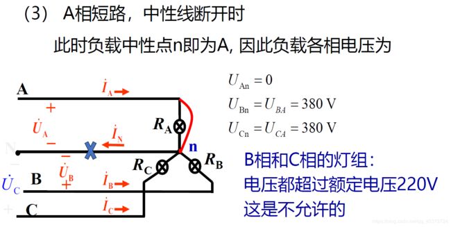
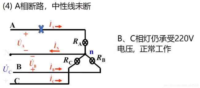
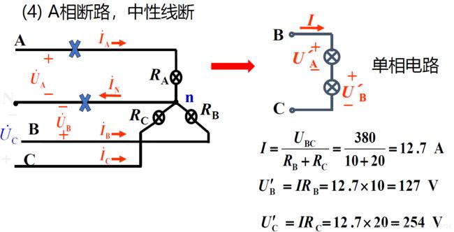
结论
1)若负载不对称且没有中线,负载的相电压就不对称当超过用电设备的额定电压时,可能烧损或减少使用寿命;而当达不到其额定电压不能正常工作
2)中线的作用:保证Y形不对称负载的相电压对称
为保证这种对称性,中线绝对不允许断开。因此,三相电源的中线内不接入熔断器或闸刀开关
三相电路的功率
一般三相电路的功率
三相瞬时功率=各相瞬时功率之和
p = p A + p B + p C p=p_A+p_B+p_C p=pA+pB+pC
三相平均功率=各相平均功率之和
P = P A + P B + P C P=P_A+P_B+P_C P=PA+PB+PC
三相无功功率=各相无功功率之和
Q = Q A + Q B + Q C Q=Q_A+Q_B+Q_C Q=QA+QB+QC
三相视在(表观)功率
S = P ² + Q ² S=\sqrt {P²+Q²} S=P²+Q²
对称三相电路的功率
三相瞬时功率=各相瞬时功率之和
p = p A + p B + p C = 3 p A p=p_A+p_B+p_C=3p_A p=pA+pB+pC=3pA
三相平均功率=各相平均功率之和
P = P A + P B + P C = 3 P A P=P_A+P_B+P_C=3P_A P=PA+PB+PC=3PA
三相无功功率=各相无功功率之和
Q = Q A + Q B + Q C = 3 Q A Q=Q_A+Q_B+Q_C=3Q_A Q=QA+QB+QC=3QA
三相视在(表观)功率
S = P ² + Q ² = 3 S A S=\sqrt {P²+Q²}=3S_A S=P²+Q²=3SA
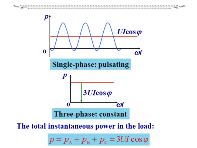
1) 对称三相电路瞬时功率的特点
p = p A + p B + p C = 3 U I c o s φ p=p_A+p_B+p_C=3UIcosφ p=pA+pB+pC=3UIcosφ
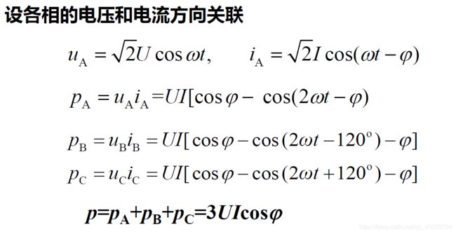
p变化速度是u和i的两倍
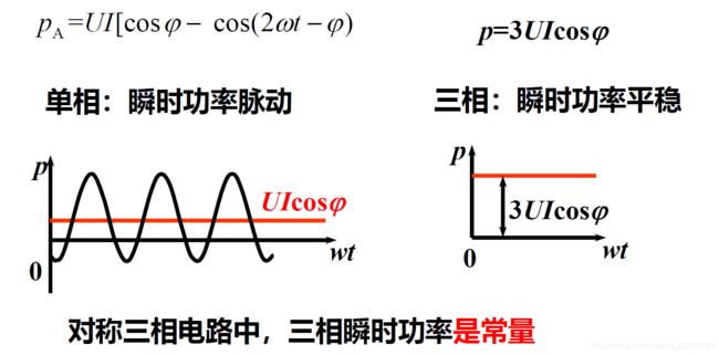
对称三相电路中,三相瞬时功率是常量
对三相发电机或三相电动机而言,瞬时功率不随时间变化意味着机械转矩不随时间变化,这样可避免它们在运转时因转矩变化而产生的震动
2) 对称三相电路平均功率的特点
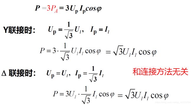
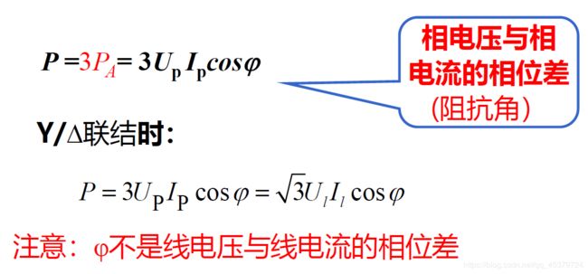
P = 3 P A = 3 U p I p c o s φ P =3P_A = 3U_p I_pcosφ P=3PA=3UpIpcosφ
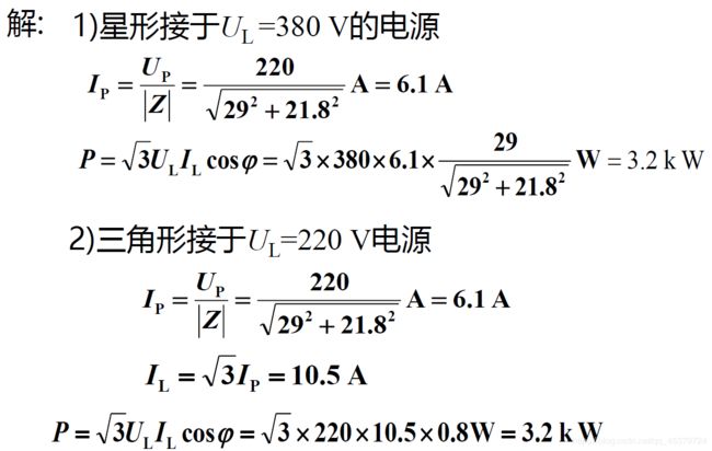
三 相 电 动 机 的 每 相 等 效 电 阻 R = 29 Ω , 等 效 感 抗 X L = 21.8 Ω , 试 求 电 动 机 的 功 率 1 ) 绕 组 联 成 星 形 接 于 U L = 380 V 的 三 相 电 源 上 2 ) 绕 组 联 成 三 角 形 接 于 U L = 220 V 的 三 相 电 源 上 三相电动机的每相等效电阻R = 29Ω,等效感抗X_L=21.8Ω,试求电动机的功率\\ 1)绕组联成星形接于U_L =380 V的三相电源上\\ 2)绕组联成三角形接于U_L=220 V的三相电源上 三相电动机的每相等效电阻R=29Ω,等效感抗XL=21.8Ω,试求电动机的功率1)绕组联成星形接于UL=380V的三相电源上2)绕组联成三角形接于UL=220V的三相电源上
工程应用1
如果电动机有两种额定电压, 如220/380 V:
当电源电压为380 V时, 电动机的绕组应联结成星形
当电源电压为220 V时, 电动机的绕组应联结成三角形
Δ和Y两种联结法中, 相电压、相电流和功率都未改变
仅三角形联结的线电流为星形联结的线电流的√3倍
工程应用2 电机星三降压启动
电机启动时定子绕组接成Y:降低启动电压,限制启动电流
启动后接成三角形,使电机全压运行
接成Y,加载绕组上的启动电压为三角形直接启动的 1 3 \frac{1}{\sqrt {3}} 31
启动电流为三角形直接启动的1/3,转矩也是直接启动的1/3
三相电路的功率测量
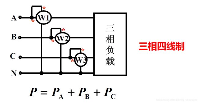
三表法(对称,非对称)
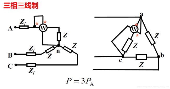
一表法(对称)
二表法(对称,不对称)
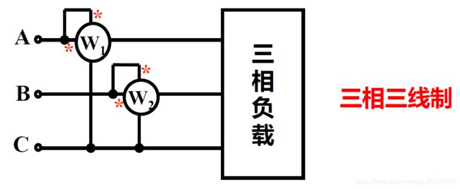
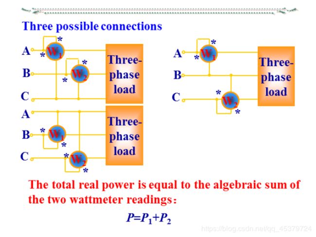
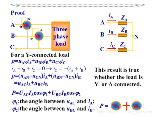
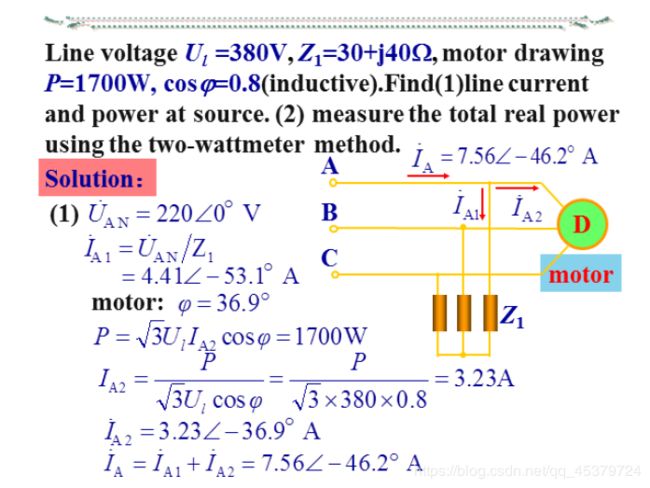
接线特点:将两功率表的电流线圈串到任意两相中,电压线圈的同名端接到其电流线圈所串的线上,电压线圈的另一端接到另一相没有串功率表的线上
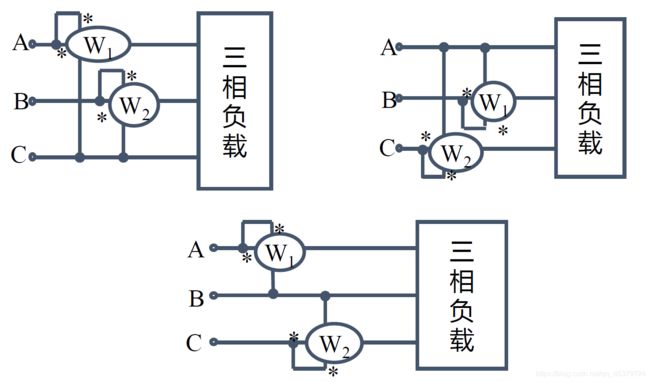
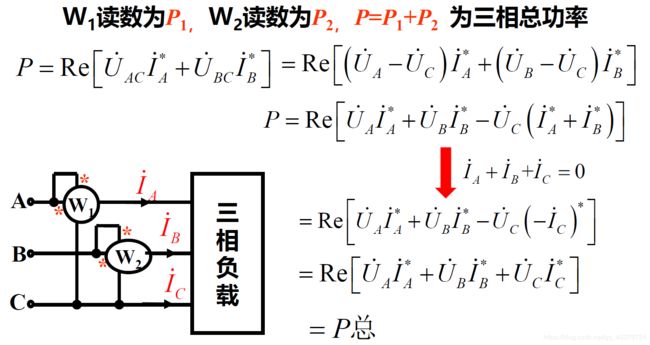
1. I ˙ A + I ˙ B + I ˙ C = 0 时 , 才 能 用 二 表 法 2. 两 表 读 数 的 代 数 和 为 三 相 总 功 率 , 每 表 的 单 独 读 数 无 意 义 3. 两 表 法 的 接 线 方 式 有 三 种 , 注 意 极 性 端 的 正 确 接 法 ( 电 压 线 圈 的 同 名 端 必 须 接 电 流 线 圈 所 在 的 那 一 条 火 线 ) 4. 按 正 确 极 性 接 线 时 , 可 能 有 一 表 的 读 数 为 负 ( 两 表 读 数 一 般 相 差 很 大 ) 1. \dot{I}_A+\dot{I}_B+\dot{I}_C=0时,才能用二表法\\ 2. 两表读数的代数和为三相总功率,每表的单独读数无意义\\ 3. 两表法的接线方式有三种,注意极性端的正确接法(电压线圈的同名端必须接电流线圈所在的那一条火线)\\ 4. 按正确极性接线时,可能有一表的读数为负(两表读数一般相差很大) 1.I˙A+I˙B+I˙C=0时,才能用二表法2.两表读数的代数和为三相总功率,每表的单独读数无意义3.两表法的接线方式有三种,注意极性端的正确接法(电压线圈的同名端必须接电流线圈所在的那一条火线)4.按正确极性接线时,可能有一表的读数为负(两表读数一般相差很大)
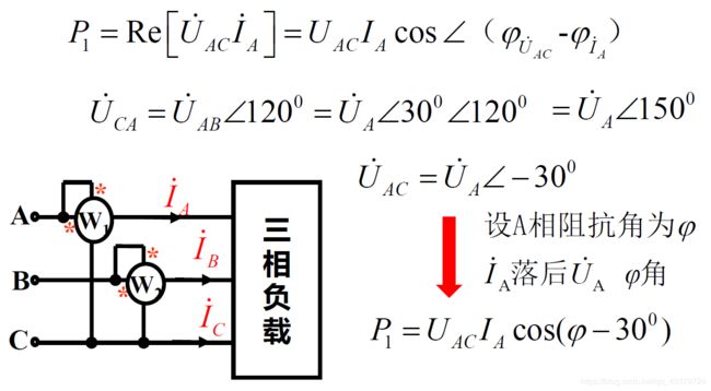
P 1 = U A C I A c o s ( φ − 30 ° ) φ ≤ − 60 ° P 1 ≤ 0 P 2 = U B C I B c o s ( φ 2 + 300 ° ) φ 2 ≥ 60 ° P 2 ≤ 0 P_1=U_{AC}I_Acos(φ-30°)~φ≤-60°~P_1≤0\\ P_2=U_{BC}I_Bcos(φ_2+300°)~φ_2≥60°~P_2≤0 P1=UACIAcos(φ−30°) φ≤−60° P1≤0P2=UBCIBcos(φ2+300°) φ2≥60° P2≤0
12.1Introduction
A single-phase ac power system consists of a generator connected through a pair of wires(a transmission line)to a load.
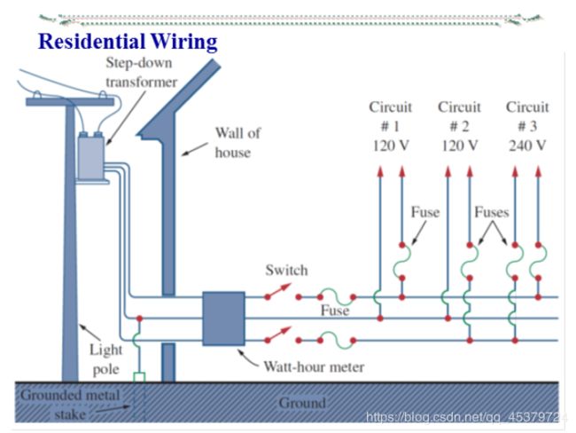
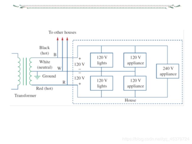
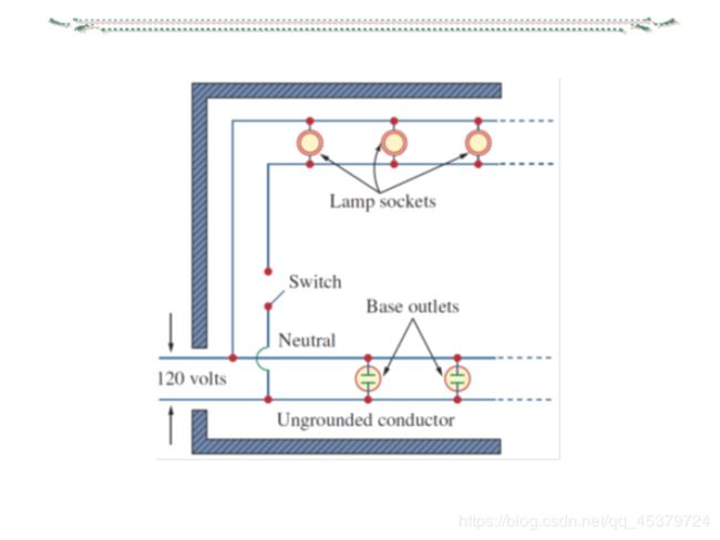
What is more common in practice is a single-phase three-wire system.It contains two identical sources(equal magnitude(量级) and the same phase)that are connected to two loads by two outer wires and the neutral.
The normal household system is a single-phase three-wire system because the terminal voltages have the same magnitude and the same phase.
Circuits or systems in which the ac sources operate at the same frequency but different phases areknown as polyphase(多相的).
The three-phase system is by far the most prevalent and most economical polyphase system.
➢Nearly all electric power is generated anddistributed in three-phase.
➢The instantaneous power in a three-phase system can be constant(not pulsating).
➢For the same amount of power,the three-phasesystem is more economical than the single-phase.
12.2 Balanced Three-Phase Voltages
A typical three-phase system consists of three voltage sources connected to loads by three or four wires(or transmission lines).
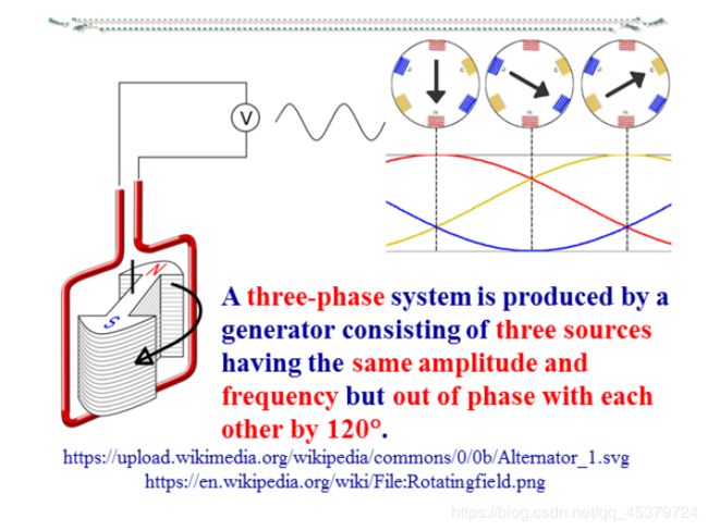
Three-phase voltages are often produced with a three-phase ac generator(or alternator).
A three-phase generator

A rotating magnet(called the rotor)surrounded by a stationary winding(called the stator).
Three separate windings or coils with terminals and are physically placed 120° apart around the stator.
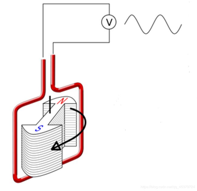
As the rotor rotates,its magnetic field “cuts” the flux from the coil and induces voltages in the coil.
A two-phase system is produced by a generator consisting of two coils placed perpendicular to each other so that the voltage generated by one lags the other by 90%.
The generator connections
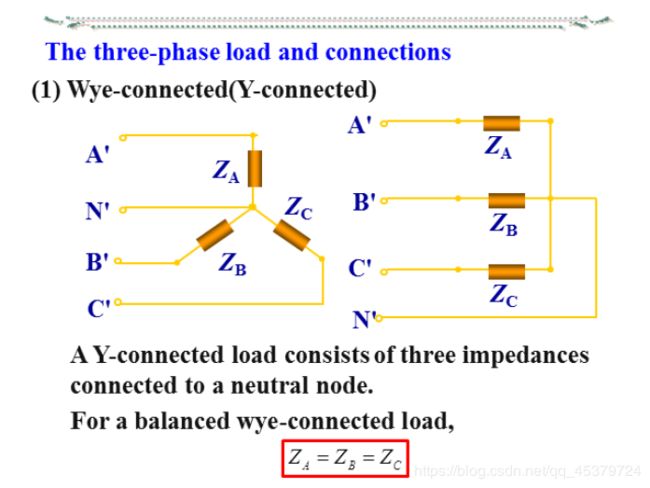
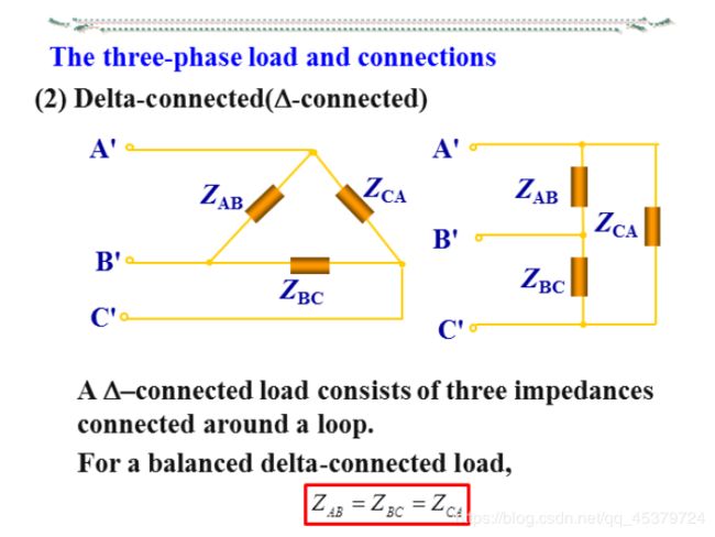
The three-phase load and connections
A balanced load is one in which the phase impedances are equal in magnitude and in phase.
A three-phase load is said to beunbalanced if the phase impedances are not equal in magnitude or phase.
The three-phase load and connections
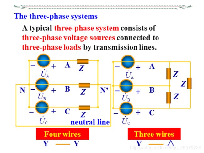
A typical three-phase system consists of three-phase voltage sources connected to three-phase loads by transmission lines.
Fourpossible connections:
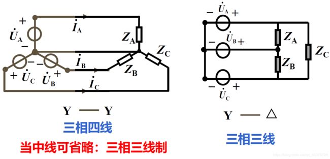
➢Y-Y(Y-connected source with a Y-connected load).
➢Y-Δ.
➢Δ-Y.
➢Δ-Δ.
Balancedthree-phase system:Sources and loads are both balanced.
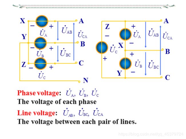
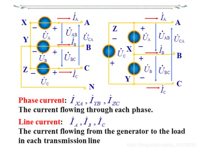
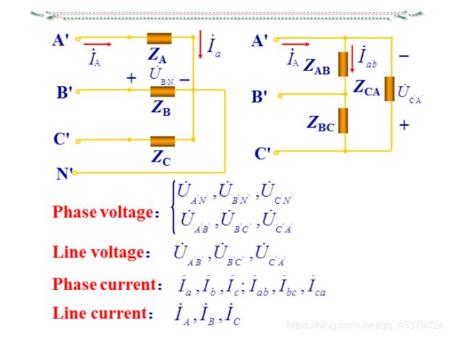
The phase voltage is the voltage of each phase of the source or load.
The phase current is the current in each phase of the source o rload.
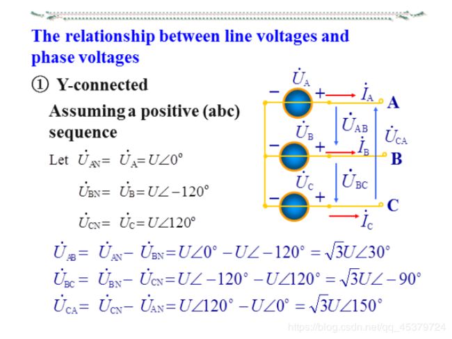
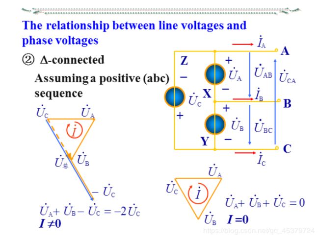
The line voltage is the voltage between each pair of lines.
The line current is the current in each transmission line(from the generator to the load).
The relationship between line voltages and phase voltages
The relationship between line currents and phase currents
12.3 Balanced Wye-Wye Connection
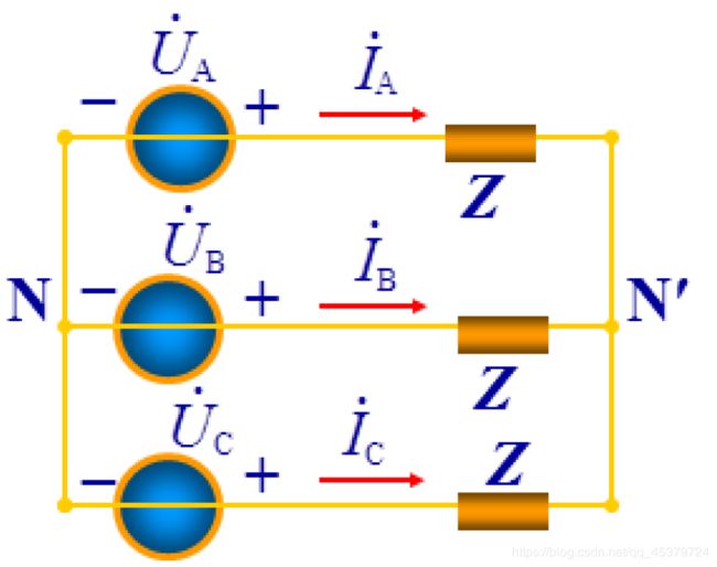
A balanced Y-Y system is a three-phase system with a balanced Y-connected source and abalanced Y-connected load.
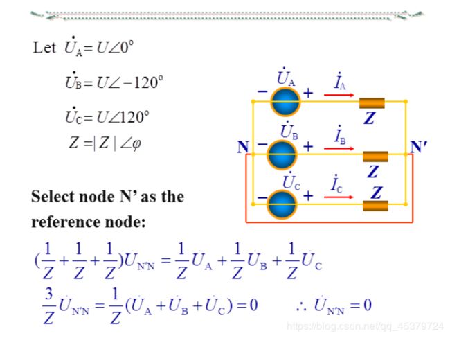
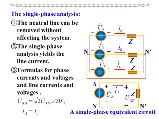
The single-phase analysis

12.4 Balanced Wye-Delta Connection
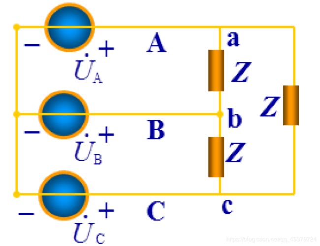
A balanced Y-A system consists of a balanced Y-connected source feeding a balanced A-connected load.
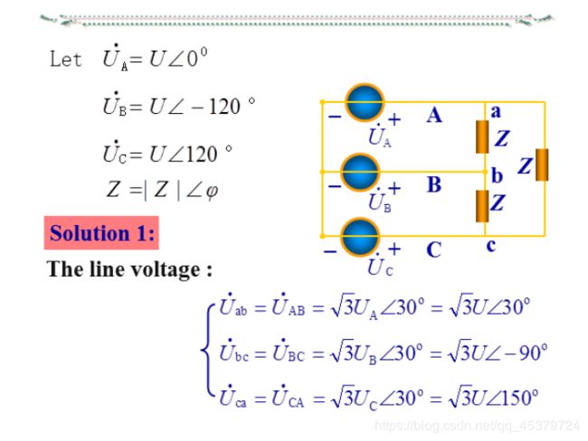
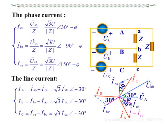
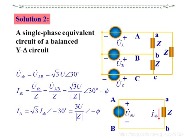
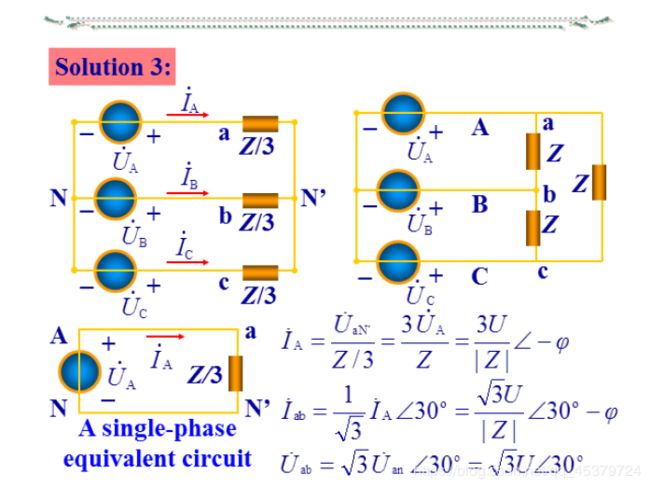
12.5 Balanced Delta-Delta Connection
A balanced Δ-Δ system is one in which boththe balanced source and balanced load are Δ-connected.
Convert both the source and the load to their Y equivalents.
12.6 Balanced Delta-Wye Connection
A balanced Δ-Y system consists of a balanced Δ-connected source feeding a balanced Y-connected load.Replace the delta-connected source with its equivalent wye-connected source.
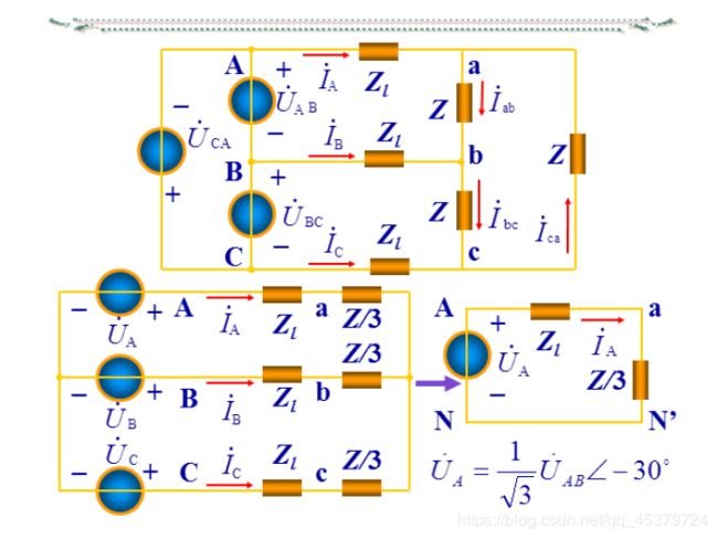
The easiest way to analyze a balanced three-phase circuit is to transform both the source and the load to a Y-Y system and then analyze the single-phase equivalentcircuit.
Understand the formulas for phase currents and voltages and line currents and voltages for the four possible configurations.
12.7 Power in a Balanced System
The instantaneous power(瞬时功率)
The average power(平均功率)
The reactive power(无功功率)
The apparent power(视在功率) and The complex power(复功率)
Three-wattmeter method(三表法)
Two-wattmeter method(两表法,与连接方式无关,)
P = P 1 + P 2 = U A C I A c o s φ 1 + U B C I B c o s φ 2 = P A + P B + P C P=P_1+P_2=U_{AC}I_Acosφ_1+U_{BC}I_Bcosφ_2=P_A+P_B+P_C P=P1+P2=UACIAcosφ1+UBCIBcosφ2=PA+PB+PC
