Gazebo环境下VIO SLAM系统实现
Gazebo环境下VIO SLAM系统实现
- Gazebo环境下VIO SLAM系统实现
- 简介
- 0. 准备工作
- 1. 搭建gazebo环境
- 1.1 相机
- 1.2 IMU
- 2.VINS-MONO
- 2.1 安装及make
- 2.2 参数修改
- 2.3 外参标定
- 2.3.1 相机旋转关节控制器
- 2.3.1 外参标定过程
- 2.4 实验效果
Gazebo环境下VIO SLAM系统实现
简介
迫于实体机器人不在手边的情形,gazebo不失为一种好的方案。但搜了下baidu和google,都没有很全的关于自己搭建gazebo环境下相机及IMU完成SLAM系统的教程,这篇文章详细介绍整个gazebo环境下的搭建过程,并实现了VINS-MONO及ORB-SLAM2开源方案的SLAM系统。同时,由于这个gazebo平台还在开发中,后期会开源出来,再更新在这里。
0. 准备工作
- Ubuntu16.04或Ubuntu18.04
- ROS-kinetic或ROS-melodic
- Gazebo7.0(其他版本应该也可以实现)
- 可以运行的gazebo及其控制包(这部分没有自己的机器人的可以直接使用开源方案https://github.com/ros-simulation/gazebo_ros_demos,虽然rrbot里以xacro为主,但是通过修改也可以实现,重点是确保有XXX_description/XXX_gazebo/XXX_control包)
1. 搭建gazebo环境
首先需要有自己的机器人平台的URDF或XACRO文件,当然有基本的可实现机器人键盘遥控运动的gazebo包,关于这块的教程网上还是比较多,大家可自己摸索实现准备工作中的第4点。
1.1 相机
由于本人研究的实体机器人使用的是realsense-d435i相机,因此相机这部分主要以d435i为主来进行实现,包括dae模型文件、深度相机等。对于不同的需求可进行修改实现。
首先需要得到相机的模型,这里参考https://github.com/pal-robotics-forks/realsense的模型dae文件(在realsense2_description/meshes中)和xacro文件(在realsense2_description/urdf中_d435.urdf.xacro)。同时还需要增加与机器人本体的关节,这里额外增加一个type为continuous的活动关节,后面SLAM中会用到,也是一个实现VINS-MONO过程中一个很关键的trick。
这里强调一下,由于深度相机与单目相机之间存在位移,并不是在同一个点,因此建立了两个link(camera_link和depth_link)以及对应的两个joint。urdf部分代码如下:
  >
  -0.0 0.0" rpy="0 0.0 0"/>
    >
      >
      >
    >
    >
        >
            >
        >
    >
  >

  >
  -0.0 0.0"
      rpy="0 0 0" />
      >
      >
      >
      >
  >
>
  -0.0 0.0" rpy="0 0.0 0"/>
    >
      >
      >
    >
    >
        >
            >
        >
    >
  >

  >
      -0.01 0.0 0.023" rpy="1.5707 0 -1.5707"/>
      >
      >
  >

  >
        >
            -0.0 -0.0 0.0 " rpy="0 0 0" />
            >
              ://amphi_description/meshes/d435.dae" />
            >
            >
                >
            >
        >
        >
          >
          >
            ://amphi_description/meshes/d435.dae" />
          >
        >
  >

  >
      -0.01 0.0 0.023" rpy="0 0 3.14159" />
      >
      >
  >

  >
    -0.0 -0.0 0.0 " rpy="0 0 0"/>
    >
      >
      >
    >
    >
        >
            >
        >
    >
  >
完成模型建立后,就需要增加gazebo部分,参考,这里的libgazebo_ros_openni_kinect.so不特定,还有很多其他如librealsense_gazebo_plugin.so都可以实现。这里可以设置图像更新频率:update_rate,图像尺寸,imageTopicName(rgb),depthImageTopicName(深度图)等参数,代码如下:
>
>
>40 >
>
>1.3962634 >
>
>R8G8B8 >
>640 >
>480 >
>
>
>0.01 >
>100 >
>
>
>
>camera >
>true >
>40 >
>rgb/image_raw >
>depth/image_raw >
>depth/points >
>rgb/camera_info >
>depth/camera_info >
>depth_link_optical >
>0.1 >
>0.0 >
>0.0 >
>0.0 >
>0.0 >
>0.0 >
>0.4 >
>
>
>
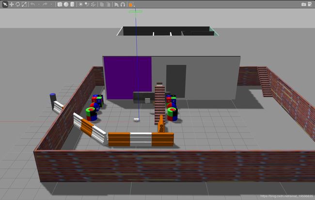
这部分代码添加到urdf文件后,roslaunch启动XXX_description中的display.launch打开RVIZ界面(刚开始启动什么都没有,需要订阅话题),XXX_gazebo中的gazebo.launch打开gazebo界面。如果你的gazebo环境中没有物体,可以拖动添加一些简单的物体到相机前方,也可以下载gazebo的模型库(参考https://blog.csdn.net/qq_40213457/article/details/81021562),建立自己world。我建的gazbeo模型如下图所示
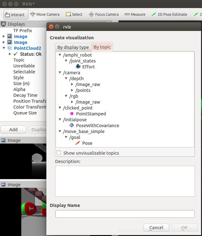
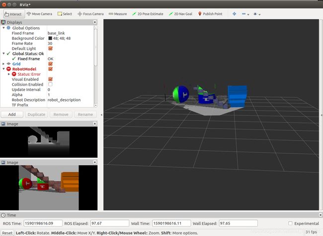
这时在RVIZ下点击add,在by topic栏下添加图像(rgb或者深度图或者点云)话题,添加过程及最后获取到的图像如下图。
1.2 IMU
在VINS-MONO中需要用到IMU来避免纯视觉方案的失效情况,因此在URDF中增加imu传感器。这部分相对于相机传感器更简单一点,直接增加gazebo部分即可,代码如下:
这里的camera_link是指imu的相对坐标系,同样可以设置更新频率update_rate、话题名称topicName。
>
>true >
>
>true >
>200 >
>true >
>__default_topic__ >
>
>d435i/imu >
>camera_link >
>200.0 >
>0.0 >
>0.0 0.0 0.0 >
>0.0 0.0 0.0 >
>imu_link_ >
>
>0 0 0 0 0 0 >
>
>
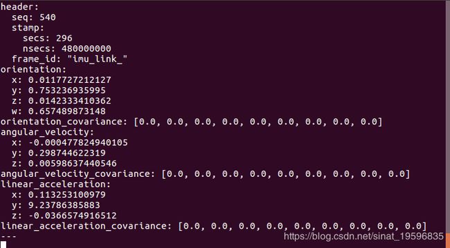
urdf文件添加完成后,启动XXX_gazebo中的gazebo.launch打开gazebo界面,由于imu数据不能在rviz中显示(可安装rviz_imu_plugin,但是试过不起作用),因此通过rostopic echo /d435i/imu来查看imu数据,具体话题名称可修改,如图。
2.VINS-MONO
完成了传感器部分,就可以通过传感器发布的话题来实现我们的SLAM系统。VINS-MONO可实现单目相机+IMU的SLAM,对于gazebo仿真平台来说,相机及IMU内参是设定好的且不需要考虑加工误差等,因此可以直接通过topic读取(rostopic echo /camera/rgb/camera_info视自己设定的话题名而定)。但难点在于IMU与相机的外参(相对位置及坐标系旋转)无法确定,gazbeo中的IMU坐标系无从获取,本人也尝试过Ethz的开源标定方案kalibr,但效果不理想,VINS-MONO还是会瞬间漂移,如下图。PS:gazebo环境下的相机标定也有一些trick,包括相机如何移动,标定板如何解决,有需要这一块工作的可以回复我。而且,camera与IMU之间的时间同步也是个问题,对于实体realsense-d435i,有额外的realsense软件包来实现时间同步,在gazebo环境下的camera与imu组合其实与普通camera+imu无差别,只是用了d435的外观dae文件。
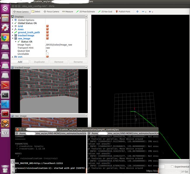
好在VINS-MONO自带Camera-Imu外参标定以及时间校准功能,可以很好的解决普适性问题。
2.1 安装及make
这一部分网上教程比较多,或者参考官方github。随便列一篇教程。
2.2 参数修改
一般教程是针对数据集,因此使用自己的设备需要修改一些参数,主要修改VINS-Mono/config/euroc/文件夹下的yaml文件。这里直接在euroc_config.yaml文件上进行修改。修改后就不再适用于官方的euroc数据集了,因此对于有一定ros基础的同学,建议重新复制出自己yaml文件,再在launch文件中修改自己的yaml文件的路径。
主要修改几个地方:
- imu_topic
- image_topic
- 相机参数(image_width、image_height、distortion_parameters、projection_parameters):获取方法同前面rostopic echo
- estimate_extrinsic:外参标定时设置为2,外参标定结束并修改外参后设置为0
- extrinsicRotation以及extrinsicTranslation:修改为外参标定过程中得到的数据
- estimate_td:时间同步,设置为1
修改后的yaml文件如下:
%YAML:1.0

#common parameters
imu_topic: "/d435i/imu"
image_topic: "/camera/rgb/image_raw"
output_path: "/home/shaozu/output/"

#camera calibration
model_type: PINHOLE
camera_name: camera
image_width: 640
image_height: 480
distortion_parameters:
   k1: 0
   k2: 0
   p1: 0
   p2: 0
projection_parameters:
   fx: 381.3625
   fy: 381.3625
   cx: 320.2
   cy: 240.5

# Extrinsic parameter between IMU and Camera.
estimate_extrinsic: 0   # 0  Have an accurate extrinsic parameters. We will trust the following imu^R_cam, imu^T_cam, don't change it.
                        # 1  Have an initial guess about extrinsic parameters. We will optimize around your initial guess.
                        # 2  Don't know anything about extrinsic parameters. You don't need to give R,T. We will try to calibrate it. Do some rotation movement at beginning.
#If you choose 0 or 1, you should write down the following matrix.
#Rotation from camera frame to imu frame, imu^R_cam
extrinsicRotation: !!opencv-matrix
   rows: 3
   cols: 3
   dt: d
   data: [-0.692596,  0.0080581,  -0.721281,
            0.033031,  -0.998534,  -0.042873,
           -0.720569, -0.0535183,   0.691315]


#Translation from camera frame to imu frame, imu^T_cam
extrinsicTranslation: !!opencv-matrix
   rows: 3
   cols: 1
   dt: d
   data: [0.0173203, -0.0361233, -0.0236887]

#feature traker paprameters
max_cnt: 150            # max feature number in feature tracking
min_dist: 30            # min distance between two features
freq: 10                # frequence (Hz) of publish tracking result. At least 10Hz for good estimation. If set 0, the frequence will be same as raw image
F_threshold: 1.0        # ransac threshold (pixel)
show_track: 1           # publish tracking image as topic
equalize: 1             # if image is too dark or light, trun on equalize to find enough features
fisheye: 0              # if using fisheye, trun on it. A circle mask will be loaded to remove edge noisy points

#optimization parameters
max_solver_time: 0.04  # max solver itration time (ms), to guarantee real time
max_num_iterations: 8   # max solver itrations, to guarantee real time
keyframe_parallax: 10.0 # keyframe selection threshold (pixel)

#imu parameters       The more accurate parameters you provide, the better performance
acc_n: 0.08          # accelerometer measurement noise standard deviation. #0.2   0.04
gyr_n: 0.004         # gyroscope measurement noise standard deviation.     #0.05  0.004
acc_w: 0.00004         # accelerometer bias random work noise standard deviation.  #0.02
gyr_w: 2.0e-6       # gyroscope bias random work noise standard deviation.     #4.0e-5
g_norm: 9.81007     # gravity magnitude

#loop closure parameters
loop_closure: 1                    # start loop closure
load_previous_pose_graph: 0        # load and reuse previous pose graph; load from 'pose_graph_save_path'
fast_relocalization: 0             # useful in real-time and large project
pose_graph_save_path: "/home/shaozu/output/pose_graph/" # save and load path

#unsynchronization parameters
estimate_td: 1                      # online estimate time offset between camera and imu
td: 0.0                             # initial value of time offset. unit: s. readed image clock + td = real image clock (IMU clock)

#rolling shutter parameters
rolling_shutter: 0                  # 0: global shutter camera, 1: rolling shutter camera
rolling_shutter_tr: 0               # unit: s. rolling shutter read out time per frame (from data sheet).

#visualization parameters
save_image: 1                   # save image in pose graph for visualization prupose; you can close this function by setting 0
visualize_imu_forward: 0        # output imu forward propogation to achieve low latency and high frequence results
visualize_camera_size: 0.4      # size of camera marker in RVIZ
2.3 外参标定
外参标定前需要保证estimate_extrinsic为2。
外参标定过程中需要保持相机一直在旋转状态,因为需要IMU的运动,且不能大幅度运动。在gazebo环境下,不能像在物理世界中一样手拿着相机做连续运动,因此这里用到前面urdf文件中设置的continuous旋转关节,通过设定旋转关节的旋转速度可以保证相机以匀速旋转用以外参标定。
2.3.1 相机旋转关节控制器
这一部分先阅读https://blog.csdn.net/banzhuan133/article/details/82717191的第3节(用ROS控制gazebo模型),已经会gazebo控制器的可以跳过。
首先需要在urdf中添加transmission标签和ros_control插件。以本文为例,其中joint name="revolute_joint"中的revolute_joint要与前面urdf中的continuous旋转关节名称对应;ros_control插件中的robotNamespace的rrbot指的是机器人名字,在urdf的第二行。代码如下:
>
>transmission_interface/SimpleTransmission >
>
>hardware_interface/VelocityJointInterface >
>
>
>VelocityJointInterface >
>1 >
>
>
>
>
>/rrbot >
>gazebo_ros_control/DefaultRobotHWSim >
>true >
>
>
添加完urdf部分后,再修改rrbot_control包下config文件夹下的yaml文件,添加控制器代码,同样joint名字要对应,这里的JointVelocityController不能修改,需要是速度控制。
  rrbot:
  # Publish all joint states -----------------------------------
  joint_state_controller:
    type: joint_state_controller/JointStateController
    publish_rate: 50

  # Position Controllers ---------------------------------------
  joint1_position_controller:
    type: effort_controllers/JointPositionController
    joint: joint1
    pid: {p: 100.0, i: 0.01, d: 10.0}
  joint2_position_controller:
    type: effort_controllers/JointPositionController
    joint: joint2
    pid: {p: 100.0, i: 0.01, d: 10.0}
  joint3_velocity_controller:
    type: velocity_controllers/JointVelocityController
    joint: revolute_joint
    pid: {p: 1000 , i: 0.01, d: 1.0}
还需要修改rrbot_control包下launch文件夹下的launch文件rrbot_control.launch,在controller_spawner代码行添加yaml文件中的控制器joint3_velocity_controller。修改后如下:
>
接下来,启动gazebo中的gazebo.launch文件,并运行以下命令,可实现相机绕z轴以0.3(单位rad/s?)的速度旋转。这里需要保证gazbeo中,相机的周围有特征点,也就是需要丰富gazebo环境,不再是一个简单的立方体。
rostopic pub -1 /rrbot/joint3_velocity_controller/command std_msgs/Float64 0.3
至此,实现在gazebo环境下相机的旋转运动,用于外参标定。
2.3.1 外参标定过程
确保VINS-Mono/config/euroc/euroc_config.yaml中的参数estimate_extrinsic为2。
gazebo环境:
运行
roslaunch rrbot gazebo.launch
VINS-MONO下:
运行
roslaunch vins_estimator euroc.launch
这时可以看到输出指令"calibrating extrinsic param, rotation movement is needed",如图

然后,在新的终端下运行让相机旋转的命令:
rostopic pub -1 /rrbot/joint3_velocity_controller/command std_msgs/Float64 0.3
这一采集过程需要等待几分钟,可以通过运行VINS-MONO下的rviz界面查看图像,如图所示。
roslaunch vins_estimator vins_rviz.launch
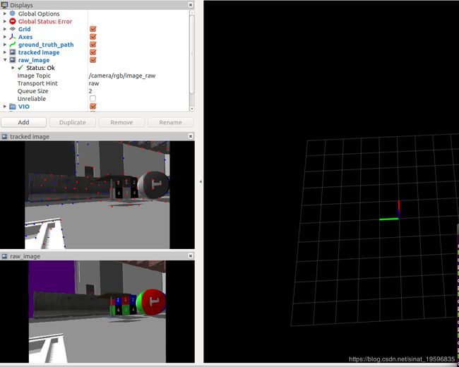
这里没办法上传视频,应该是相机一直在旋转采集图像,等待几分钟后roslaunch vins_estimator euroc.launch窗口输出结果,如图所示。


将结果
-0.561508  0.0300504    0.826925
0.0498908  -0.996293   0.0700826
0.825966   0.0806079   0.557927
0.0110133 0.027835 0.0234937
替换euroc_config.yaml中的extrinsicRotation和extrinsicTranslation中的data,替换后如下:
extrinsicRotation: !!opencv-matrix
   rows: 3
   cols: 3
   dt: d
   data: [-0.561508,  0.0300504,    0.826925,
			0.0498908,  -0.996293,   0.0700826,
			0.825966,   0.0806079,   0.557927]


#Translation from camera frame to imu frame, imu^T_cam
extrinsicTranslation: !!opencv-matrix
   rows: 3
   cols: 1
   dt: d
   data: [0.0110133,	0.027835,	0.0234937]
至此,标定过程结束。
2.4 实验效果
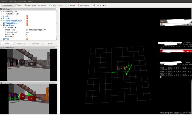
通过修改参数后,明显漂移会减少很多。但是因为VINS-MONO需要IMU不断运动,由于本项目的机器人及gazebo环境比较大,使得机器人的速度运行很慢,导致VINS-MONO效果不是很好,后期还需要优化。但是经过外参标定后的VINS-MONO的漂移减少很多。