ros_arduino_bridge+arduino+l298n控制编码电机(Arduino uno)
踩了许多坑,看了许多教程,终于成功用ros_arduino桥的方法实现了对电机的控制,希望大家能通过我的教训少走一些弯路。
注:本教程的所有代码可以进入我主页下载
step1:
ubuntu下安装arduino IDE(具体方法可直接搜索,这里就暂时略过)
step2:
利用arduino IDE将下位机代码烧录到arduino中,注意我使用的是arduino uno,而很多教程使用的是arduino mega2560,不同的板子应该对代码进行适当的修改,好,话不多说,我们来看看具体步骤。
step2.1:进入catkin_ws/src git下来官方的包
cd ~/catkin_ws/src
git clone https://github.com/hbrobotics/ros_arduino_bridge.git
然后回到catkin_ws并编译
cd ..
catkin_make
step2.2:将上一步下载的包中的下位机代码复制入arduino的库(libraries)中。
先进入到sketchbook的libraries目录下,一般都在home里,很好找
cd ~/sketchbook/libraries
\cp -rp ~/catkin_ws/src/ros_arduino_bridge/ros_arduino_firmware/src/libraries/ROSArduinoBridge -T ROSArduinoBridge
step2.3:根据所选用的驱动和板子修改ROSArduinoBridge及相关代码
#define USE_BASE // Enable the base controller code
//#undef USE_BASE // Disable the base controller code
/* Define the motor controller and encoder library you are using */
#ifdef USE_BASE
/* The Pololu VNH5019 dual motor driver shield */
//#define POLOLU_VNH5019
/* The Pololu MC33926 dual motor driver shield */
//#define POLOLU_MC33926
/* The RoboGaia encoder shield */
//#define ROBOGAIA
/* Encoders directly attached to Arduino board */
#define ARDUINO_ENC_COUNTER
/* L298 Motor driver*/
#define L298_MOTOR_DRIVER
#endif
主要就是这个地方需要修改,我都标蓝了,这里千万要修改对,看清楚哪里注释了哪里没有注释
修改之后电机ide左上方向左的箭头,进行烧录
step3:
下一步我们查看编码器以及电机的相关接口的定义,一定要按照这个来连线!
首先是编码器,编码器的两个信号反馈线按照下列方式直接连到uno上:
#ifdef ARDUINO_ENC_COUNTER
//below can be changed, but should be PORTD pins;
//otherwise additional changes in the code are required
#define LEFT_ENC_PIN_A PD2 //pin 2
#define LEFT_ENC_PIN_B PD3 //pin 3
//below can be changed, but should be PORTC pins
#define RIGHT_ENC_PIN_A PC4 //pin A4
#define RIGHT_ENC_PIN_B PC5 //pin A5
#endif
由于我只拿了一个电机做实验,所以只连接了2和3这两个
如果有两路电机,左侧电机的编码输出接D2,D3;右侧电机的编码输出接A4,A5
然后是电机
#ifdef L298_MOTOR_DRIVER
#define RIGHT_MOTOR_BACKWARD 5
#define LEFT_MOTOR_BACKWARD 6
#define RIGHT_MOTOR_FORWARD 9
#define LEFT_MOTOR_FORWARD 10
#define RIGHT_MOTOR_ENABLE 12
#define LEFT_MOTOR_ENABLE 13
#endif
可以看到 5 6 9 10是四个控制电机转动的输出口,我只连了5和6
其他都是供电线,该怎么连怎么连就行
step4:
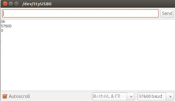
调试,打开serial monitor 根据command.h里面的相关提示输入指令查看反馈,
一定要注意波特率调到57600
主要指令:
a 模拟读入 例如 a 3
b 获取波特率
c 设置某引脚状态
d 读取某引脚状态 例如 d 4
e
m 设定速度 例如 m 20 20
p
r 复位
s 舵机写值
t 舵机读值
u 更新PID
w 数字写0/1
x 模拟写
0
1
例如如果你想从模拟引脚pin3读取数据,你就可以使用这个命令:
a 3
如果你想改变数字引脚pin3的模式为OUTPUT,就发送这个命令:
c 3 1
要得到目前编码器的计数,你可以用这个命令:
e
把机器人以每秒20个encoder ticks的速度向前移动,可以使用命令:
m 20 20
之后你会看到反馈到了数据,这样说明目前为止没有问题
对了,多说一句,arduino和你的主控连接的串口一定要搞明白 是usb0还是acm0
可以通过插拔检查
step5:
接下来我们试一下上位机用ros节点的方式与arduino通信,注意 这时一定要关闭刚才的monitor
配置ros_arduino_python节点
既然你的Arduino已经可以按要求运行sketch了,那么现在你就可以在你的PC上把它配置为ROS节点。你可以在通过编辑ros_arduino_python/config路径下的YAML文件定义的机器人尺寸,PID参数,以及传感器配置信息。所以首先进入到这个路径中:
$ roscd ros_arduino_python/config你可以把这个提供的配置文件拷贝一份然后再修改(名字可以自定义):
$ cp arduino_params.yaml my_arduino_params.yaml现在你可以使用任何你所喜欢的编辑器来编辑这个配置文件的副本(my_arduino_params.yaml),打开之后应该是这个样子:
# For a direct USB cable connection, the port name is typically
# /dev/ttyACM# where is # is a number such as 0, 1, 2, etc
# For a wireless connection like XBee, the port is typically
# /dev/ttyUSB# where # is a number such as 0, 1, 2, etc.

port: /dev/ttyUSB0
baud: 57600
timeout: 0.1

rate: 50
sensorstate_rate: 10

use_base_controller: False
base_controller_rate: 10

# For a robot that uses base_footprint, change base_frame to base_footprint
base_frame: base_link

# === Robot drivetrain parameters
#wheel_diameter: 0.146
#wheel_track: 0.2969
#encoder_resolution: 8384 # from Pololu for 131:1 motors
#gear_reduction: 1.0
#motors_reversed: True

# === PID parameters
#Kp: 10
#Kd: 12
#Ki: 0
#Ko: 50
#accel_limit: 1.0

# === Sensor definitions.  Examples only - edit for your robot.
#     Sensor type can be one of the following:
#     * Ping
#     * GP2D12
#     * Analog
#     * Digital
#     * PololuMotorCurrent
#     * PhidgetsVoltage
#     * PhidgetsCurrent (20 Amp, DC)


sensors: {
  #motor_current_left:   {pin: 0, type: PololuMotorCurrent, rate: 5},
  #motor_current_right:  {pin: 1, type: PololuMotorCurrent, rate: 5},
  #ir_front_center:      {pin: 2, type: GP2D12, rate: 10},
  #sonar_front_center:   {pin: 5, type: Ping, rate: 10},
  onboard_led:           {pin: 13, type: Digital, rate: 5, direction: output}
}

# Joint name and configuration is an example only
joints: {
    head_pan_joint: {pin: 3, init_position: 0, init_speed: 90, neutral: 90, min_position: -90, max_position: 90, invert: False, continuous: False},
    head_tilt_joint: {pin: 5, init_position: 0, init_speed: 90, neutral: 90, min_position: -90, max_position: 90, invert: False, continuous: False}
}NOTE:不要在你的.yaml文件里使用tab,否则的话这个语法解析器会无法加载它。如果你要缩进的话必须用空格代替tab键。
ALSO:当定义你的传感器参数时,列表中的最后一个传感器的行尾(花括号后面)后没有逗号,但是其余的行尾必须有逗号。
现在让我们一起浏览一下这个文件的每一部分。
接口设置
这个接口要么是/dev/ttyACM0,要么是/dev/ttyUSB0,视情况而定,而且前面我们也已经提到过这个。
其中MegaRobogaiaPololu的Arudino sketch默认是以57600的波特率连接的。
轮询速率
跳出ROS loop运行的速率主要就取决于这个速率参数(默认为50Hz),这个默认值足以满足大多数情况。在任何情况下,它应该至少与你的传感器的最大速率(下面我们会说到)一样快才行。
sensorstate_rate决定了多久发布一个所有传感器的集合列表,每个传感器也以各自的速率在各自的主题上发布消息。
use_base_controller参数默认为False。你可以把它设置为True(假设你有文中所要求的硬件设施)。下面你将必须设置PID参数。
base_controller_rate参数决定了多久发布一次里程计读取信息。
定义传感器
sensors参数按照定义了传感器的名字和参数的字典。(你可以给你的传感器起任何你喜欢的名字,但是你必须要知道传感器的名字也会成为那个传感器所对应主题的名字。
这四个最重要的参数分别是:pin,type,rate,direction。rate定义了你每秒想轮询一次那个传感器多少次。例如,一个电压传感器可能每秒仅仅被轮询一次(或者仅仅每两秒一次),而一个声呐传感器可能每秒被轮询20次。type必须是列表中被列出来的(注意区分大小写!)。direction默认是input,所以如果你想将它定义为output,就将这个direction单独设为output。在上面的例子中,Arduino LED(pin13)将会以每秒两次的速率被点亮或熄灭。
设置Drivetrain(驱动系统)和PID参数
为了使用基础控制器(base controller),你必须去掉它的注释并且设置机器人的drivetrain和PID参数。示例中drivetrain参数是直径6英寸的驱动轮,距离11.5英寸。注意在ROS中使用米作为距离单位,所以一定要换算单位。示例中的编码器的分辨率(每转的tick数)规格来自于Pololu 131:1电动机。为你的电动机/编码器组合设置合理的数值。如果你的轮子向后转的话,那么就把motors_reversed设置为true,否则的话就设置为False。
PID参数比较难设置,你可以先按照示例中的值设置。但是在你第一次发送转弯命令的时候,一定要把你的机器人放在小块儿上。
启动ros_arduino_python节点
你现在看一下路径ros_arduino_python/launch下的文件arduino.launch。正如你所看到的,它指向一个名叫my_arduino_params.yaml的文件(之前创建的)。
如果你的配置文件命名不同,那么就把这里的文件名参数(my_arduino_params.yaml)修改成你的配置文件的名字。
当你连接好Arduino并运行MegaRobogaiaPololu sketch时,使用下面的参数来启动 ros_arduino_python node节点:
$ roslaunch ros_arduino_python arduino.launchNOTE:启动之前,千万不要打开Arduino IDE 的串口监视器,因为串口监视器会与该节点争夺串口资源。
你应该看到下面这样的输出:
process[arduino-1]: started with pid [6098]
Connecting to Arduino on port /dev/ttyUSB0 …
Connected at 57600
Arduino is ready.
[INFO] [WallTime: 1355498525.954491] Connected to Arduino on port / > dev/ttyUSB0 at 57600 baud
[INFO] [WallTime: 1355498525.966825] motor_current_right {‘rate’: 5, > ‘type’: ‘PololuMotorCurrent’, ‘pin’: 1}
[INFO]
etc
如果你在你的机器人上装的有Ping声呐而且你也在配置文件里面定义了它们,它们就会闪一下来告诉你已经连接成功。
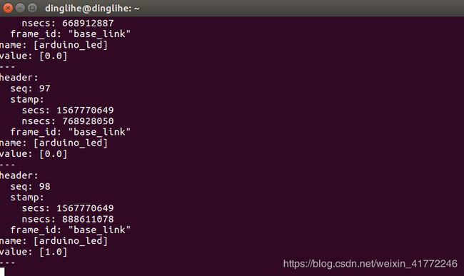
查看传感器数据
你可以回显传感器状态主题来查看所有传感器的数据:
$ rostopic echo /arduino/sensor_state回显相应传感器的主题名字你就可以查看任何指定的传感器数据:
rostopic echo /arduino/sensor/sensor_name例如,你有一个叫做
ir_front_center的传感器,那么你可以运行下面的命令来查看相应的数据:
$ rostopic echo /arduino/sensor/ir_front_center你也可以使用rqt_plot来将这系列数据用图像的形式表示出来:
$ rqt_plot /arduino/sensor/ir_front_center/range

如上图所示那么恭喜你成功一半了,下来我们要根据你的底盘和编码器信息修改my_arduino_params.yaml文件
# For a direct USB cable connection, the port name is typically
# /dev/ttyACM# where is # is a number such as 0, 1, 2, etc
# For a wireless connection like XBee, the port is typically
# /dev/ttyUSB# where # is a number such as 0, 1, 2, etc.port: /dev/ttyUSB0
baud: 57600
timeout: 0.1rate: 50
sensorstate_rate: 10use_base_controller: True
base_controller_rate: 10# For a robot that uses base_footprint, change base_frame to base_footprint
base_frame: base_link# === Robot drivetrain parameters
wheel_diameter: 0.146
wheel_track: 0.2969
encoder_resolution: 8384 # from Pololu for 131:1 motors
gear_reduction: 1.0
motors_reversed: True# === PID parameters
Kp: 10
Kd: 12
Ki: 0
Ko: 50
accel_limit: 1.0# === Sensor definitions. Examples only - edit for your robot.
# Sensor type can be one of the follow (case sensitive!):
# * Ping
# * GP2D12
# * Analog
# * Digital
# * PololuMotorCurrent
# * PhidgetsVoltage
# * PhidgetsCurrent (20 Amp, DC)sensors: {
#motor_current_left: {pin: 0, type: PololuMotorCurrent, rate: 5},
#motor_current_right: {pin: 1, type: PololuMotorCurrent, rate: 5},
#ir_front_center: {pin: 2, type: GP2D12, rate: 10},
#sonar_front_center: {pin: 5, type: Ping, rate: 10},
arduino_led: {pin: 13, type: Digital, rate: 5, direction: output}
}
发送Twist命令与查看里程计数据
把你的机器人放到块上使轮子悬空,然后发布一个Twist命令:
$ rostopic pub -1 /cmd_vel geometry_msgs/Twist '{ angular: {z: 0.5} }'
两个轮子的转动方向应该是一致的,都是逆时针转动(右轮前进,左轮后退)。如果它们转动方向相反,那么就将motors_reversed 参数改为与之前相反的值,然后用ctrl+c 停止该节点,然后重新启动arduino.launch文件。
使用下面的命令可以使机器人停止:
$ rostopic pub -1 /cmd_vel geometry_msgs/Twist '{}'
要查看里程数据可以运行:
$ rostopic echo /odom
或者使用图形界面显示:
$ rxplot -p 60 /odom/pose/pose/position/x:y, /odom/twist/twist/linear/x, /odom/twist/twist/angular/z
ROS服务
ros_arduino_python功能包也定义了一些ROS服务,如下所示:
digital_set_direction-设置数字引脚的方向
$ rosservice call /arduino/digital_set_direction pin direction这里pin是引脚数字,direction为0代表输入,1代表输出。
digital_write-给数字引脚发送高低电平(LOW为0,HIGH为1)
$ rosservice call /arduino/digital_write pin value同样,这里pin是引脚数字,value是电平高低(LOW为0,HIGH为1)。
servo_write-设置伺服机位置
$ rosservice call /arduino/servo_write id pos这里id是伺服机的索引号(定义在Arduino sketch中的servos.h)并且pos是以弧度为单位(0-3.14),头文件servos.h中具体是这样写的:
byte servoInitPosition [N_SERVOS] = { 90, 90 }; // [0, 180] degreesservo_read -读取伺服机的位置
$ rosservice call /arduino/servo_read id