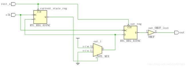
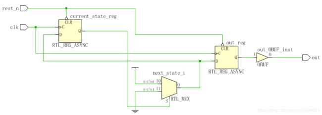
三种状态机——分析、对比和小结
本文简化所有逻辑重点讲解状态机的框架。
先给几点小结:
小结1.在原理图和实际变现上来说,一段式和三段式完全一致,但在代码量大的情况下三段式代码更容易维护。
小结2.二段式的输出由组合逻辑驱动,不仅可能输出毛刺,而且不利于时许约束、分析。
小结3.状态机有着流水线的“缺点”:上电之初若不全面指定初始状态,则可能有若干个时钟的无效输出。
状态机一般有3个基本组成要素:
要素1.新状态
要素2.当前状态
要素3.输出
当每个clk到来,要完成3个任务:
任务1.将“新状态”赋给“当前状态”
任务2.产生下一个“新状态”(可能包含组合逻辑)
任务3.根据“当前状态”产生输出(可能包含组合逻辑)
以下分别给出三种状态机的框架代码、原理图、仿真激励代码和仿真波形图
一段式:
形式上,丢掉“新状态”这个媒介,直接把新状态的值赋给“当前状态”,故没有任务2。
形式上,在一个触发器里完成任务1、3,但实际上这需要2个触发器,因为1个触发器只有一组输出/输入。
module one_state_machine(
    input clk,
    input rest_n,
    output out
    );

reg out,current_state,next_state;

always@(posedge clk or negedge rest_n) //״̬תӆ
begin
    if(!rest_n)
        begin out <= 1'd0;current_state <= 1'b0; end
    else
        case(current_state)
            1'b0:   begin out <= 1'b1;current_state <= 1'b1; end
            1'b1:   begin out <= 1'b0;current_state <= 1'b0; end
            default:begin out <= 1'b0;current_state <= 1'b1; end
        endcase
end

endmodule
二段式:
用1个触发器完成任务1,用一个组合逻辑完成任务2、3。最后的输出由组合逻辑驱动,可能会产生毛刺,不利于时序分析和优化。
module two_state_machine(
    input clk,
    input rest_n,
    output out
    );

reg out,current_state,next_state;

always@(posedge clk or negedge rest_n) //״̬תӆ
begin
    if(!rest_n)
        current_state<=1'b0;
    else
        current_state<=next_state;
end

always@(*)
begin
    case(current_state)
        1'b0:   begin out = 1'd1; next_state = 1'b1; end
        1'b1:   begin out = 1'd0; next_state = 1'b0; end
        default:begin out = 1'd0; next_state = 1'b1; end
    endcase
end

endmodule
三段式:
一个触发器完成任务1,一个组合逻辑完成任务2,一个触发器完成任务3
module three_state_machine(
    input clk,
    input rest_n,
    output out
    );

reg out,current_state,next_state;

always@(posedge clk or negedge rest_n)
begin
    if(!rest_n)
        current_state<=1'b0;
    else
        current_state<=next_state;
end

always @ (current_state)
begin
    case(current_state)
        1'b0:   next_state = 1'b1;
        1'b1:   next_state = 1'b0;
        default:next_state = 1'b1;
    endcase
end

always@(posedge clk or negedge rest_n)
begin
    if(!rest_n)
        out <= 1'd0;
    else
        case(current_state)
        1'b0:   out <= 1'd1;
        1'b1:   out <= 1'd0;
        default:out <= 1'd0;
        endcase
end

endmodule
仿真激励代码:
`timescale 1ns / 1ps
module testbench_one_state_machine;
reg clk,rest_n;
wire out;

one_state_machine U0 (
         .clk(clk),
         .rest_n(rest_n),
         .out(out)
         );

initial
begin// this process block specifies the stimulus.
    rest_n = 0;
    #50
    rest_n = 1;
end

initial begin
    clk = 0;
    forever #10 clk = ~clk;
end

endmodule
本文逻辑简单,三种状态机波形几乎一致。


