4. MIZ7035 HDMI测试【PCIE视频传输】
1 MIZ7035的HDMI工程建立
将上次用到的MIG_AXI工程拿来进行HDMI的工程建立。
不像ZCU102的开发板那样用GT收发器,MIZ7035的HDMI接口是靠PL的逻辑来实现输入输出的。所以要写RTL代码来做HDMI的编解码。
测了几天MIZ7035的这个板子,遇到了个问题,总结一下。
1 BUFx时钟问题
写这个文档时候我已经测试了一天了,就先将一个比较重要的问题提前抛出来。米联的MIZ7035的原理图可以下载到,可以自行下载去查看。
首先是HDMI的TMDS的信号FPGA并不能够直接进行连接,所以需要进行信号转换、改变耦合方式、加偏置等方法对信号进行处理,这里就不讨论了。
再来看HDMI的信号连接到了哪个BANK。可以看到两个HDMI都连接到了FPGA的BANK 35。那么问题来了,这样会有什么问题。
Digilent出了很多带双路FPGA的开发板,看了几块都是讲HDMI的输入输出放在了不同的BANK。如下图的zybo_z7开发板
1.png
Zynq7000的PL的BANK最多只能有一个CMT,而每一个CMT中包含一个MMCM和一个PLL,两个都可以产生高速时钟。HDMI输入输出的RTL都是通过使用IOSERDES、IODELAY的源语来实现串并、并串转换的。
它们的CLK、CLKDIV输入的来源有2个
- 片上BUFx的输出
- MMCM/PLL经BUFx的输出
不管用哪种方式,其实都是必须经过BUFx进行缓冲的。
BUFx可用的组合方式可以看xapp585,
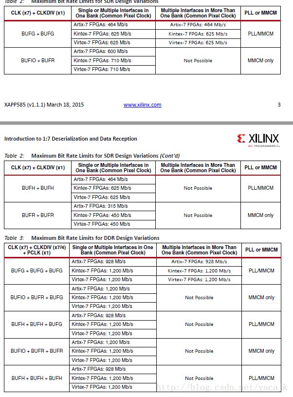
而XC7Z035-2的速率如下图。
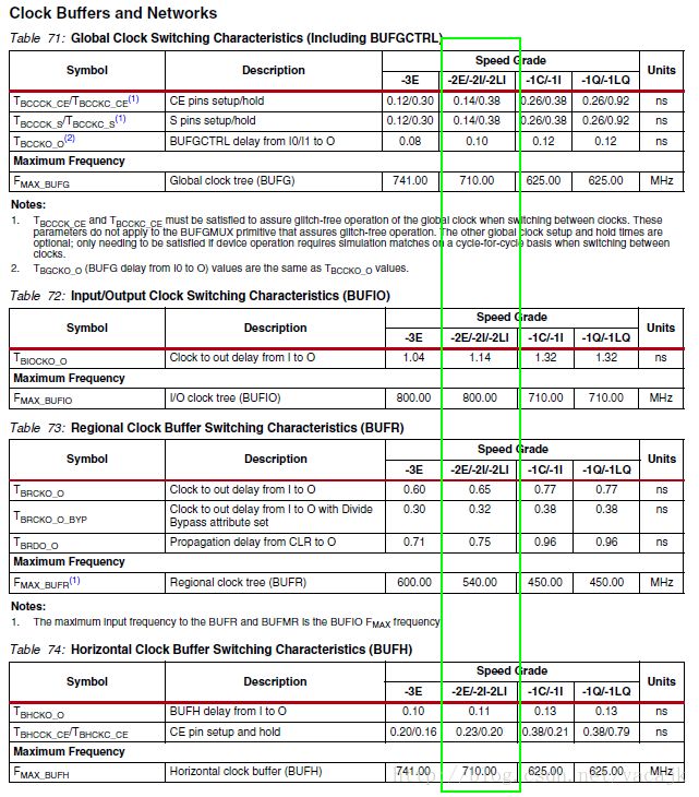
BUFG:710MHz,BUFIO:800MHz,BUFR:540MHz,BUFH:710MHz。
我们测试时使用的最大图像分辨率为1920*1080,他的像素时钟为148.5MHz,TMDS上使用DDR方式则穿行时钟是5倍的像素时钟为742.5MHz。
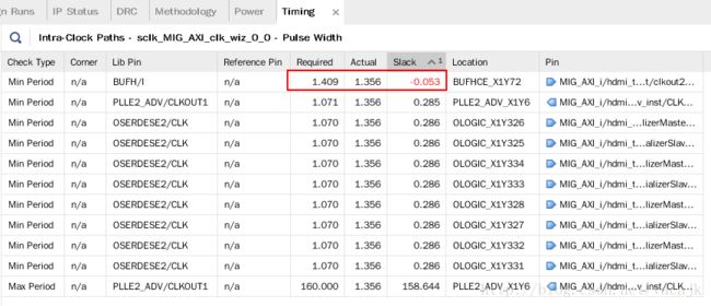
若使用BUFx作为SERDES的输入时,我们仅仅只有BUFIO+BUFR这个组合能够满足芯片要求,而其他的肯定会有警告或是错误。(实际也确实是这样,板子带的代码没用唯一可选的组合,而是选了两个BUFG来实现,实现完成后即可看到有一个时钟周期不满足要求的时序错误。)但是实际测试HDMI输出是可以正常使用的,毕竟官方标的BUFG 710MHz是严格的测试标准下得到的数据,肯定还有一部分余量。但是为了更加的可靠,还是将这个时序错误避免掉比较好。
但是,看BUFIO加BUFR的这个组合只能够使用MMCM来实现连接,而一个BANK中只有一个MMCM,所以在MIZ7035中,BUFx这个方法肯定不能满足了。。假设一个HDMI通道用了MMCM+BUFIO+BUFR,则另外一个通道只能有以下情况:
- MMCM+BUFG+BUFG,因为BUFIO不能跨时钟域
- PLL+BUFH/BUFG+BUFH/BUFG,因为这个BANK只剩下一个PLL了
不管使用上面的那种方式,都不可能满足742.5MHz的DDR模式的。
看来BUFx的任何组合是不能够满足要求了!那么我们只能接收这个时序错误了,假设BUFG或BUFH的上限710MHz是能够接受742.5MHz信号,并应该没有问题的。。
这个坑自己设计原理图时候可以考虑一下,最好将它们放在不同的BANK中,并且都使用MMCM+BUFIO+BUFR就好了。
2 HDMI&MIG问题
除了前面这个问题,还有个问题就是HDMI和MIG各自的BANK是紧邻的。
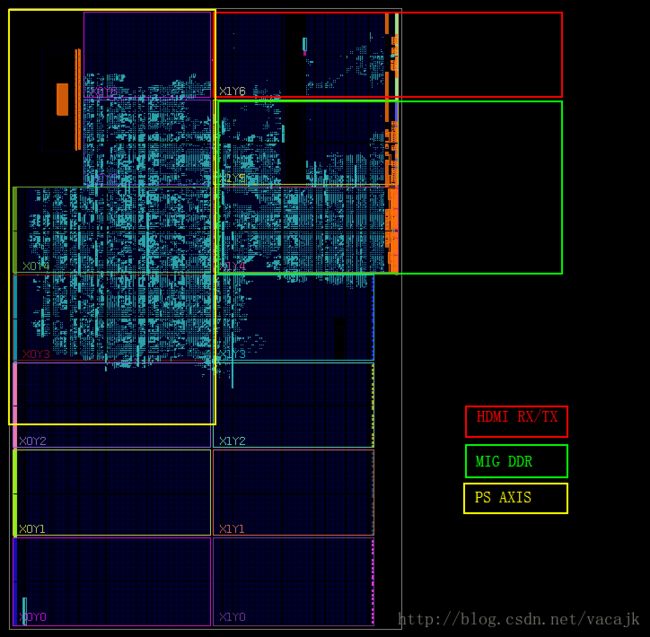
因为HDMI的输入、输出还要连接vid、vtc、fifo等IP,会占用挺多的资源,跟MIG这边一扎堆,很容易造成AXI Lite接口不满足时序要求等情况。
3 HDMI RX的HPD
HDMI的HPD信号是由接收设备传输给输出设备的。MIZ7035的HDMI RX连接到电脑上,HPD信号是由开发板传给电脑的,高电平会指示电脑有显示器连接上、低电平指示没有显示器连接。高电平在网上可以查到说至少要大于+2.4V,具体从哪出来的这个要求,我还没找到源头。
再来看MIZ7035的原理图,HDMI RX的连接器下拉10K电阻到地,然后连接了TXS0108。这就有问题了!因为TXS系列的电平转换芯片我经常用,我知道这个电平转换芯片是双向的,而且每个引脚上有一个上拉电阻,查看datasheet可以看到这个上拉电阻是40K(低电平时)或是4K(高电平时)。
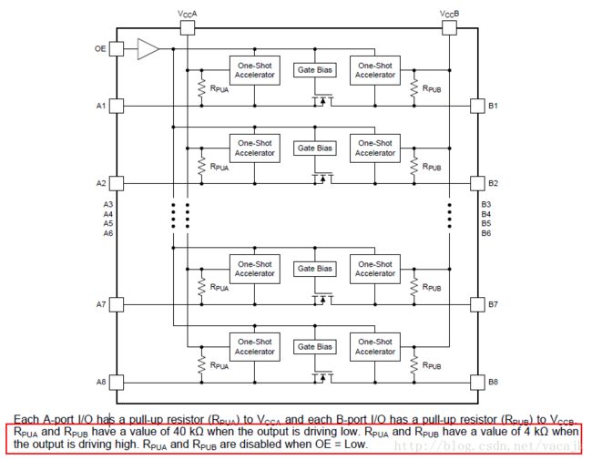
那么当我们用FPGA驱动输出高电平时,H1_HPD这个信号的输出将是3.3V的分压,3.3*10/(4+10)=2.357V,不满足+2.4V的要求。用万用表实际测量,这个电压为2.262V,电源为3.321V。后面测试时插上电脑时候,确实电脑没有输出任何信号,看来得改一下板子的电路了。
可以选择将这个电阻换大一点的阻值,如30K时可以让高电平达到2.9V,来试试吧,在手头找了一个相近的34.8K的电阻,把板子上的R53换掉。重新测了一下HPD电压,为2.838V,可以满足要求了。而且插上电脑,电脑确实闪烁了。虽然这样看起来可以了,但还是有问题啊。只能说HPD需要一个强的驱动,TXS却不能提供一个默认低电平的输出。
同样是TXS0108内部上拉,当我们的配置不使用LED相关引脚时,上拉电阻会将该芯片管脚拉高,并使LED灯点亮。。而且这个点亮是高电平驱动的,,但怎么说呢这个芯片不适合输出电流去驱动LED,至少我以前用都是这样的。
4 demo移植
接着进行工程建立。
先从github上下载Digilent的IP,最新的IP加了ila,禁止ila的话有bug。就用之前的一个版本吧:https://github.com/digilent/vivado-library/tree/7827858e39f0a02b8ec579150110c073050aaada
下载Zybo Z7-20的HDMI demo,https://github.com/Digilent/Zybo-Z7-20-hdmi
参考zybo的demo,加入各IP进入到我们的MIG_AXI工程中,主要包括了rgb2dvi、dvi2rgb、vtc、vid。而demo中的axi_dynclk就不加入工程了。我们固定使用1080p的视频输出。
各IP配置如下
dvi2rgb
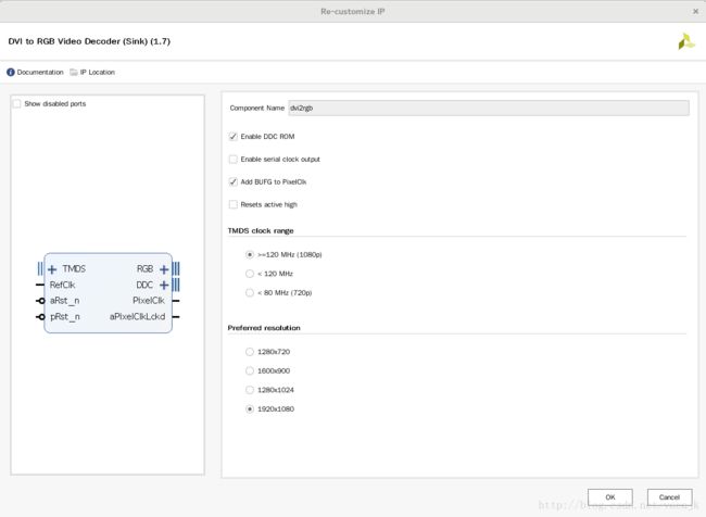
rgb2div
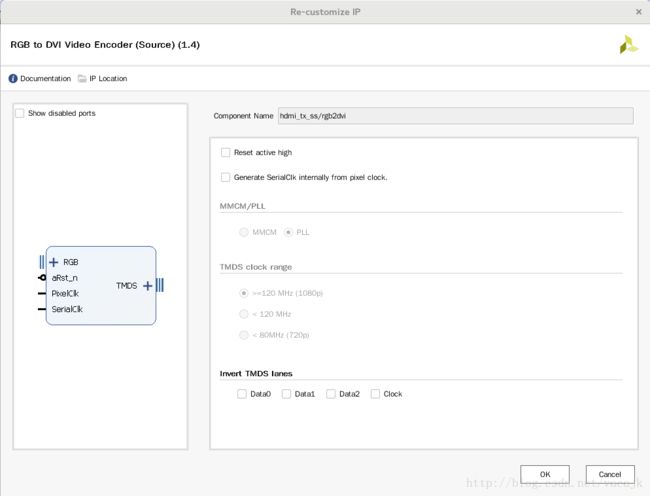
输入输出各自的vtc、vid参考demo即可。demo中的vdma ip我们不去使用。
图像数据与DDR的交互使用了tpg、mix、frmbuf_wr,跟ZCU102中的配置相同,区别在于为了跨不同BANK,我们在两个AXI4-Stream Register Slice与其相连的IP间插入了一个AXI4-Stream Data FIFO。
整体框图如下
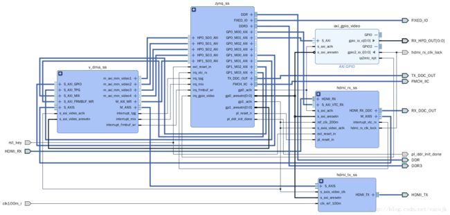
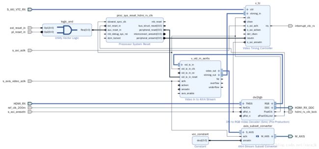
hdmi_rx_ss
hdmi_tx_ss
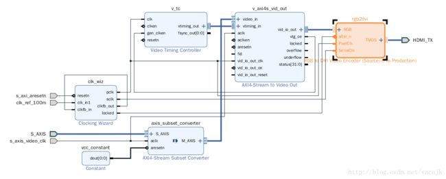
其中的clk_wiz配置如下
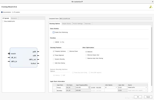
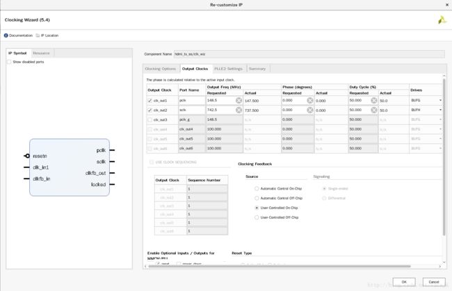
clk_wiz的fb输入输出直接相连接,没有经过任何BUF,因为我们用到的pclk和sclk的相位关系在HDMI TX中并不重要,axi_dynclk的源码中有写。
v_dma_ss
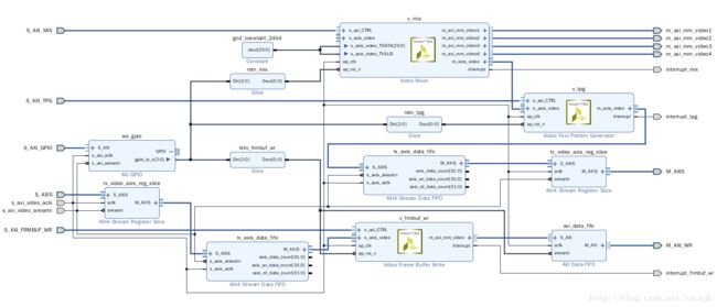
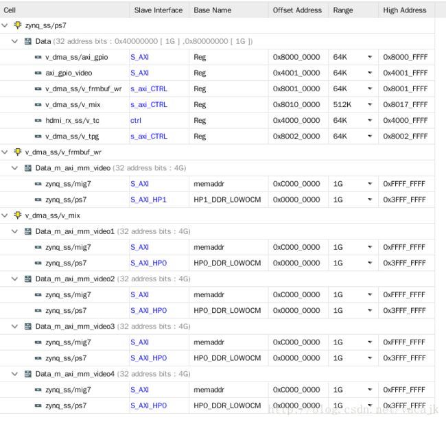
zynq_ss,v_dma_ss过来的HP信号同时接入了PS和MIG,这样就能够我们自行选择用哪一边的DDR了。但是PL端的DDR在这个设计中PS是没有寻址的,所以访问不了。

addree配置,pl ddr定位到了0xC000000,1GB空间。
约束
set_property LOC PLLE2_ADV_X1Y6 [get_cells MIG_AXI_i/hdmi_tx_ss/clk_wiz/inst/plle2_adv_inst]
set_property LOC MMCME2_ADV_X1Y6 [get_cells MIG_AXI_i/hdmi_rx_ss/dvi2rgb/U0/TMDS_ClockingX/DVI_ClkGenerator]


create_clock -name clk100m_i -period 10.00 [get_ports clk100m_i]
#set_property VCCAUX_IO DONTCARE [get_ports clk100m_i]
set_property IOSTANDARD SSTL15 [get_ports clk100m_i]
set_property PACKAGE_PIN C8 [get_ports clk100m_i]

#rst_key, active low
set_property PACKAGE_PIN A10 [get_ports rst_key]
set_property IOSTANDARD LVCMOS15 [get_ports rst_key]

#led 0
set_property PACKAGE_PIN B9 [get_ports pl_ddr_init_done]
set_property IOSTANDARD LVCMOS15 [get_ports pl_ddr_init_done]
#led 1
set_property PACKAGE_PIN K10 [get_ports hdmi_rx_clk_lock]
set_property IOSTANDARD LVCMOS15 [get_ports hdmi_rx_clk_lock]

#HDMI RX
create_clock -name HDMI_RX_clk_p -period 6.734 [get_ports HDMI_RX_clk_p]
set_property PACKAGE_PIN D15 [get_ports HDMI_RX_clk_p]
set_property IOSTANDARD LVDS [get_ports HDMI_RX_clk_p]
set_property PACKAGE_PIN E16 [get_ports HDMI_RX_data_p[0]]
set_property IOSTANDARD LVDS [get_ports HDMI_RX_data_p[0]]
set_property PACKAGE_PIN F15 [get_ports HDMI_RX_data_p[1]]
set_property IOSTANDARD LVDS [get_ports HDMI_RX_data_p[1]]
set_property PACKAGE_PIN C17 [get_ports HDMI_RX_data_p[2]]
set_property IOSTANDARD LVDS [get_ports HDMI_RX_data_p[2]]

set_property PACKAGE_PIN B10 [get_ports RX_DDC_OUT_scl_io]
set_property IOSTANDARD LVCMOS15 [get_ports RX_DDC_OUT_scl_io]
set_property PACKAGE_PIN B15 [get_ports RX_DDC_OUT_sda_io]
set_property IOSTANDARD LVCMOS18 [get_ports RX_DDC_OUT_sda_io]
set_property PACKAGE_PIN B16 [get_ports RX_HPD_OUT]
set_property IOSTANDARD LVCMOS18 [get_ports RX_HPD_OUT]

#HDMI TX
set_property PACKAGE_PIN J14 [get_ports HDMI_TX_clk_p]
set_property IOSTANDARD LVDS [get_ports HDMI_TX_clk_p]
set_property PACKAGE_PIN K13 [get_ports HDMI_TX_data_p[0]]
set_property IOSTANDARD LVDS [get_ports HDMI_TX_data_p[0]]
set_property PACKAGE_PIN G14 [get_ports HDMI_TX_data_p[1]]
set_property IOSTANDARD LVDS [get_ports HDMI_TX_data_p[1]]
set_property PACKAGE_PIN K15 [get_ports HDMI_TX_data_p[2]]
set_property IOSTANDARD LVDS [get_ports HDMI_TX_data_p[2]]

set_property PACKAGE_PIN H13 [get_ports TX_DDC_OUT_scl_io]
set_property IOSTANDARD LVCMOS18 [get_ports TX_DDC_OUT_scl_io]
set_property PACKAGE_PIN G15 [get_ports TX_DDC_OUT_sda_io]
set_property IOSTANDARD LVCMOS18 [get_ports TX_DDC_OUT_sda_io]

set_property PACKAGE_PIN A17 [get_ports FMCH_IIC_scl_io]
set_property IOSTANDARD LVCMOS18 [get_ports FMCH_IIC_scl_io]
set_property PACKAGE_PIN B17 [get_ports FMCH_IIC_sda_io]
set_property IOSTANDARD LVCMOS18 [get_ports FMCH_IIC_sda_io]
编译
资源占用
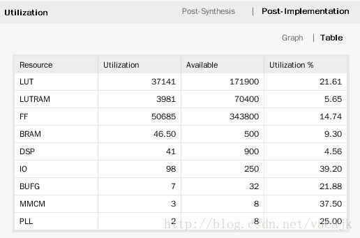
时序错误,bufh不能达到742.5MHz

资源分布
生成并输出hdf with bit。
2 工程测试
1 TPG测试
先写一个截断MIX,从TPG直接产生pattern输出的驱动。测试代码:
#include
#include "platform.h"
#include "xil_printf.h"

#include "sleep.h"
#include "xgpio.h"
#include "xvidc.h"
#include "xv_tpg.h"
#include "xv_mix_l2.h"
#include "xv_frmbufwr_l2.h"

XGpio   Gpio_VDMA_resetn;
XGpio   Gpio_RXHPD;
XV_tpg  Tpg;
XV_Mix_l2       Mix;
XV_FrmbufWr_l2  FrmbufWr;

int init_gpio(void)
{
    int Status;
    Status = XGpio_Initialize(&Gpio_VDMA_resetn, XPAR_V_DMA_SS_AXI_GPIO_DEVICE_ID);
    if(Status != XST_SUCCESS) {
    xil_printf("ERR:: GPIO VDMA device not found\r\n");
        return(XST_FAILURE);
    }

    XGpio_SetDataDirection(&Gpio_VDMA_resetn, 1, 0);
    XGpio_DiscreteWrite(&Gpio_VDMA_resetn, 1, 0x0);
    usleep(1000);
    XGpio_DiscreteWrite(&Gpio_VDMA_resetn, 1, 0x7);
    usleep(1000);

    Status = XGpio_Initialize(&Gpio_RXHPD, XPAR_AXI_GPIO_VIDEO_DEVICE_ID);
    if(Status != XST_SUCCESS) {
    xil_printf("ERR:: GPIO HPD device not found\r\n");
        return(XST_FAILURE);
    }

    XGpio_SetDataDirection(&Gpio_RXHPD, 1, 0);
    XGpio_DiscreteWrite(&Gpio_RXHPD, 1, 0x0);
    usleep(1000);
    XGpio_DiscreteWrite(&Gpio_RXHPD, 1, 0x1);
    usleep(1000);

    return (XST_SUCCESS);
}

int init_tpg(void)
{
    int Status;
    Status = XV_tpg_Initialize(&Tpg, XPAR_V_DMA_SS_V_TPG_DEVICE_ID);
    if(Status != XST_SUCCESS) {
    xil_printf("ERR:: TPG device not found\r\n");
        return(XST_FAILURE);
    }

    //Stop TPG
    XV_tpg_DisableAutoRestart(&Tpg);

    XV_tpg_Set_height(&Tpg, 1080);
    XV_tpg_Set_width(&Tpg, 1920);
    XV_tpg_Set_ovrlayId(&Tpg, 0);
    XV_tpg_Set_colorFormat(&Tpg, XVIDC_CSF_RGB);
    XV_tpg_Set_bckgndId(&Tpg, XTPG_BKGND_TARTAN_COLOR_BARS);

    //move box
    XV_tpg_Set_ovrlayId(&Tpg, 1);
    XV_tpg_Set_boxSize(&Tpg,80);
    //if in YUV mode, R->Y,G->U,B->V,wrong ,it is g b r
    XV_tpg_Set_boxColorR(&Tpg,255);
    XV_tpg_Set_boxColorG(&Tpg,255);
    XV_tpg_Set_boxColorB(&Tpg,255);
    XV_tpg_Set_motionSpeed(&Tpg,1);

    //Start TPG
    XV_tpg_EnableAutoRestart(&Tpg);
    XV_tpg_Start(&Tpg);
    xil_printf("INFO: TPG configured\r\n");

    return (XST_SUCCESS);
}

int main()
{
    init_platform();

    print("Hello World\n\r");

    init_gpio();
    init_tpg();

    cleanup_platform();
    return 0;
}
将HDMI TX连接到显示器,将HDMI RX连接到电脑。下载bit、elf,运行程序,首先可以看到显示器显示出了测试图像,上面的方形白色的色块也可以正常移动;然后电脑屏幕闪了一下,看来是发现新的显示器了,打开NVIDIA控制面板,可以看到我们的新显示设备了DigilentDVI-3。
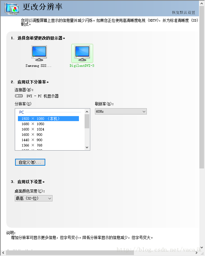
能读到显示器的配置,证明DDC接口的EDID信息能够正常传输。这个显示设备的名称,我们可以在dvi2rgb的IP目录中修改对应的数据即可。
再观察一下开发板上的LED,
- LED0亮了,表示pl_ddr_init_done有效,MIG模块初始化PL DDR完成
- LED1亮了,表示HDMI RX IP: dvi2rgb模块接收到了HDMI输入时钟信号,并已经倍频锁定。
2 MIX测试
首先官方的standalone mix bsp有个bug..,在xv_mix_l2.c文件中。
 WinResInRange = ((Win->Width  > (XVMIX_MIN_STRM_WIDTH-1))  &&
                  (Win->Height > (XVMIX_MIN_STRM_HEIGHT-1)) &&
                  (Win->Width  < MixPtr->Config.LayerMaxWidth[LayerId-1]) &&
                  (Win->Height <= MixPtr->Config.MaxHeight));
中间有一句:Win->Width < MixPtr->Config.LayerMaxWidth[LayerId-1]
是小于号而不是等于号,其实是不对的,判断条件应该是小于等于才对,否则我们将不能配置最大1920宽度的图像输入。可以选择修改bsp里面的源码,或者修改mix ip核的配置。为了方便,我直接在SDK的安装目录里面对bsp的代码进行了修改。
测试代码:
#include
#include "platform.h"
#include "xil_printf.h"
#include "xil_cache.h"

#include "sleep.h"
#include "xgpio.h"
#include "xvidc.h"
#include "xv_tpg.h"
#include "xv_mix_l2.h"
#include "xv_frmbufwr_l2.h"

XGpio   Gpio_VDMA_resetn;
XGpio   Gpio_RXHPD;
XV_tpg  Tpg;
XV_Mix_l2       Mix;
XV_FrmbufWr_l2  FrmbufWr;

extern unsigned char Logo_R[];
extern unsigned char Logo_G[];
extern unsigned char Logo_B[];
extern unsigned char Logo_A[];

#define DEMO_PATTERN_0 0
#define DEMO_PATTERN_1 1
#define TPG_PASSTHROUGH_DISABLE 0
#define TPG_PASSTHROUGH_ENABLE 1

int init_gpio(void)
{
    int Status;
    Status = XGpio_Initialize(&Gpio_VDMA_resetn, XPAR_V_DMA_SS_AXI_GPIO_DEVICE_ID);
    if(Status != XST_SUCCESS) {
    xil_printf("ERR:: GPIO VDMA device not found\r\n");
        return(XST_FAILURE);
    }

    XGpio_SetDataDirection(&Gpio_VDMA_resetn, 1, 0);
    XGpio_DiscreteWrite(&Gpio_VDMA_resetn, 1, 0x7);
    usleep(10000);
    XGpio_DiscreteWrite(&Gpio_VDMA_resetn, 1, 0x0);
    usleep(10000);
    XGpio_DiscreteWrite(&Gpio_VDMA_resetn, 1, 0x7);
    usleep(10000);

    Status = XGpio_Initialize(&Gpio_RXHPD, XPAR_AXI_GPIO_VIDEO_DEVICE_ID);
    if(Status != XST_SUCCESS) {
    xil_printf("ERR:: GPIO HPD device not found\r\n");
        return(XST_FAILURE);
    }

    XGpio_SetDataDirection(&Gpio_RXHPD, 1, 0);
    usleep(10000);
    XGpio_DiscreteWrite(&Gpio_RXHPD, 1, 0x0);
    usleep(10000);
    XGpio_DiscreteWrite(&Gpio_RXHPD, 1, 0x1);
    usleep(10000);

    return (XST_SUCCESS);
}

int init_tpg(int IsPassThrough)
{
    int Status;
    Status = XV_tpg_Initialize(&Tpg, XPAR_V_DMA_SS_V_TPG_DEVICE_ID);
    if(Status != XST_SUCCESS) {
    xil_printf("ERR:: TPG device not found\r\n");
        return(XST_FAILURE);
    }

    //Stop TPG
    XV_tpg_DisableAutoRestart(&Tpg);

    XV_tpg_Set_height(&Tpg, 1080);
    XV_tpg_Set_width(&Tpg, 1920);
    XV_tpg_Set_ovrlayId(&Tpg, 0);
    XV_tpg_Set_colorFormat(&Tpg, XVIDC_CSF_RGB);
    XV_tpg_Set_bckgndId(&Tpg, XTPG_BKGND_TARTAN_COLOR_BARS);

    //move box
    XV_tpg_Set_ovrlayId(&Tpg, 1);
    XV_tpg_Set_boxSize(&Tpg,80);
    //if in YUV mode, R->Y,G->U,B->V,wrong ,it is g b r
    XV_tpg_Set_boxColorR(&Tpg,255);
    XV_tpg_Set_boxColorG(&Tpg,255);
    XV_tpg_Set_boxColorB(&Tpg,255);
    XV_tpg_Set_motionSpeed(&Tpg,1);

    if (IsPassThrough) {
        XV_tpg_Set_enableInput(&Tpg, IsPassThrough);
        XV_tpg_Set_passthruStartX(&Tpg,0);
        XV_tpg_Set_passthruStartY(&Tpg,0);
        XV_tpg_Set_passthruEndX(&Tpg,1920);
        XV_tpg_Set_passthruEndY(&Tpg,1080);
    }

    //Start TPG
    XV_tpg_EnableAutoRestart(&Tpg);
    XV_tpg_Start(&Tpg);
    xil_printf("INFO: TPG configured\r\n");

    return (XST_SUCCESS);
}

int init_mix(void)
{
    int Status;
    Status  = XVMix_Initialize(&Mix, XPAR_V_DMA_SS_V_MIX_DEVICE_ID);
        if(Status != XST_SUCCESS) {
        xil_printf("ERR:: Mixer device not found\r\n");
        return(XST_FAILURE);
    }

    XVidC_VideoStream VidStrm;
    u32 width, height;

    XVidC_VideoWindow Win_Logo;
    XVidC_VideoWindow Win_Layer1;
    u32 Stride_Layer1;

    width       = 1920;
    height  = 1080;

  //Stop TPG
    XVMix_Stop(&Mix);

    VidStrm.VmId           = XVIDC_VM_1080_60_P;
    VidStrm.ColorFormatId  = XVIDC_CSF_RGB;
    VidStrm.FrameRate      = XVIDC_FR_60HZ;
    VidStrm.IsInterlaced   = FALSE;
    VidStrm.ColorDepth     = XVIDC_BPC_8;
    VidStrm.PixPerClk      = XVIDC_PPC_1;
    VidStrm.Timing.HActive = width;
    VidStrm.Timing.VActive = height;
    XVMix_SetVidStream(&Mix, &VidStrm);

    u32 MemAddr = 0x10000000;
    Status = XVMix_SetLayerBufferAddr(&Mix, XVMIX_LAYER_1, MemAddr);
    if(Status != XST_SUCCESS) {
        xil_printf("MIXER ERR:: Unable to set layer %d buffer addr to 0x%X\r\n", XVMIX_LAYER_1, MemAddr);
    }

    Win_Layer1.StartX   = 0;
    Win_Layer1.StartY   = 0;
    Win_Layer1.Width    = width;
    Win_Layer1.Height   = height;
    Stride_Layer1       =   width*3;
    XVMix_SetLayerWindow(&Mix, XVMIX_LAYER_1, &Win_Layer1, Stride_Layer1);

    Win_Logo.StartX = 0;
    Win_Logo.StartY = 0;
    Win_Logo.Width      = 64;
    Win_Logo.Height = 64;
    if(XVMix_IsLogoEnabled(&Mix)) {
        Status = XVMix_LoadLogo(&Mix, &Win_Logo, Logo_R, Logo_G, Logo_B);
        if(Status != XST_SUCCESS) {
            xil_printf("MIXER ERR:: Unable to load Logo \r\n");
        }
        if(XVMix_IsLogoPixAlphaEnabled(&Mix)) {
            Status = XVMix_LoadLogoPixelAlpha(&Mix, &Win_Logo, Logo_A);
            if(Status != XST_SUCCESS) {
                xil_printf("MIXER ERR:: Unable to load Logo pixel alpha \r\n");
            }
        }
    } else {
        xil_printf("INFO: Logo Layer Disabled in HW \r\n");
    }


    XVMix_SetLayerAlpha(&Mix, XVMIX_LAYER_1, 255);
    XVMix_SetLayerAlpha(&Mix, XVMIX_LAYER_2, 255);
    XVMix_SetLayerAlpha(&Mix, XVMIX_LAYER_3, 255);
    XVMix_SetLayerAlpha(&Mix, XVMIX_LAYER_4, 255);
    XVMix_SetLayerAlpha(&Mix, XVMIX_LAYER_LOGO, 255);   //alpha layer should set to 255, then it will be enable to display
    XVMix_SetBackgndColor(&Mix, XVMIX_BKGND_RED, XVIDC_BPC_8);

    XVMix_LayerDisable(&Mix, XVMIX_LAYER_ALL);
    XVMix_LayerEnable(&Mix, XVMIX_LAYER_1);
    XVMix_LayerEnable(&Mix, XVMIX_LAYER_LOGO);

    //Start Mix
    XVMix_InterruptDisable(&Mix);
    XVMix_Start(&Mix);

    xil_printf("INFO: Mixer configured\r\n");

    usleep(1000);
    XVMix_DbgReportStatus(&Mix);
    XVMix_DbgLayerInfo(&Mix,XVMIX_LAYER_1);

    return (XST_SUCCESS);
}

void DemoPrintTest(u8 *frame, u32 width, u32 height, u32 stride, int pattern)
{
    u32 xcoi, ycoi;
    u32 iPixelAddr;
    u8 wRed, wBlue, wGreen;
    u32 wCurrentInt;
    double fRed, fBlue, fGreen, fColor;
    u32 xLeft, xMid, xRight, xInt;
    u32 yMid, yInt;
    double xInc, yInc;

    switch (pattern)
    {
    case DEMO_PATTERN_0:

        xInt = width / 4; //Four intervals, each with width/4 pixels
        xLeft = xInt * 3;
        xMid = xInt * 2 * 3;
        xRight = xInt * 3 * 3;
        xInc = 256.0 / ((double) xInt); //256 color intensities are cycled through per interval (overflow must be caught when color=256.0)

        yInt = height / 2; //Two intervals, each with width/2 lines
        yMid = yInt;
        yInc = 256.0 / ((double) yInt); //256 color intensities are cycled through per interval (overflow must be caught when color=256.0)

        fBlue = 0.0;
        fRed = 256.0;
        for(xcoi = 0; xcoi < (width*3); xcoi+=3)
        {
            /*
             * Convert color intensities to integers < 256, and trim values >=256
             */
            wRed = (fRed >= 256.0) ? 255 : ((u8) fRed);
            wBlue = (fBlue >= 256.0) ? 255 : ((u8) fBlue);
            iPixelAddr = xcoi;
            fGreen = 0.0;
            for(ycoi = 0; ycoi < height; ycoi++)
            {

                wGreen = (fGreen >= 256.0) ? 255 : ((u8) fGreen);
                frame[iPixelAddr] = wRed;
                frame[iPixelAddr + 1] = wBlue;
                frame[iPixelAddr + 2] = wGreen;
                if (ycoi < yMid)
                {
                    fGreen += yInc;
                }
                else
                {
                    fGreen -= yInc;
                }

                /*
                 * This pattern is printed one vertical line at a time, so the address must be incremented
                 * by the stride instead of just 1.
                 */
                iPixelAddr += stride;
            }

            if (xcoi < xLeft)
            {
                fBlue = 0.0;
                fRed -= xInc;
            }
            else if (xcoi < xMid)
            {
                fBlue += xInc;
                fRed += xInc;
            }
            else if (xcoi < xRight)
            {
                fBlue -= xInc;
                fRed -= xInc;
            }
            else
            {
                fBlue += xInc;
                fRed = 0;
            }
        }
        /*
         * Flush the framebuffer memory range to ensure changes are written to the
         * actual memory, and therefore accessible by the VDMA.
         */
        Xil_DCacheFlushRange((unsigned int) frame, width * stride);
        break;
    case DEMO_PATTERN_1:

        xInt = width / 7; //Seven intervals, each with width/7 pixels
        xInc = 256.0 / ((double) xInt); //256 color intensities per interval. Notice that overflow is handled for this pattern.

        fColor = 0.0;
        wCurrentInt = 1;
        for(xcoi = 0; xcoi < (width*3); xcoi+=3)
        {

            /*
             * Just draw white in the last partial interval (when width is not divisible by 7)
             */
            if (wCurrentInt > 7)
            {
                wRed = 255;
                wBlue = 255;
                wGreen = 255;
            }
            else
            {
                if (wCurrentInt & 0b001)
                    wRed = (u8) fColor;
                else
                    wRed = 0;

                if (wCurrentInt & 0b010)
                    wBlue = (u8) fColor;
                else
                    wBlue = 0;

                if (wCurrentInt & 0b100)
                    wGreen = (u8) fColor;
                else
                    wGreen = 0;
            }

            iPixelAddr = xcoi;

            for(ycoi = 0; ycoi < height; ycoi++)
            {
                frame[iPixelAddr] = wRed;
                frame[iPixelAddr + 1] = wBlue;
                frame[iPixelAddr + 2] = wGreen;
                /*
                 * This pattern is printed one vertical line at a time, so the address must be incremented
                 * by the stride instead of just 1.
                 */
                iPixelAddr += stride;
            }

            fColor += xInc;
            if (fColor >= 256.0)
            {
                fColor = 0.0;
                wCurrentInt++;
            }
        }
        /*
         * Flush the framebuffer memory range to ensure changes are written to the
         * actual memory, and therefore accessible by the VDMA.
         */
        Xil_DCacheFlushRange((unsigned int) frame, width * stride);
        break;
    default :
        xil_printf("Error: invalid pattern passed to DemoPrintTest");
    }
}

void DemoLogoTest(void)
{
    u16 logo_x=0;
    u16 logo_y=200;
    while(1)
    {
        usleep(10000);
        if(logo_x < 1920-64)
            logo_x++;
        else
            logo_x = 0;
        XVMix_MoveLayerWindow(&Mix, XVMIX_LAYER_LOGO,logo_x,logo_y);
        XVMix_MoveLayerWindow(&Mix, XVMIX_LAYER_LOGO,logo_x,logo_y);
    }
}
int main()
{
    init_platform();

    print("Hello World\n\r");

    //frame base, 1920*1080*3
    u8 *pixel_base;
    pixel_base=(u8 *)0x10000000;
    u32 f_width, f_height, f_stride;
    f_width = 1920;
    f_height    = 1080;
    f_stride    = 1920 * 3;

    print("step 1: test tpg output\n\r");
    init_gpio();
    init_tpg(TPG_PASSTHROUGH_DISABLE);
    usleep(6000000);

    print("step 2: enable tpg passthrough and init mix\n\r");
    init_gpio();
    init_mix();
    init_tpg(TPG_PASSTHROUGH_ENABLE);
    usleep(6000000);

    print("step 3: test display pattern 0\n\r");
    DemoPrintTest(pixel_base, f_width, f_height, f_stride, DEMO_PATTERN_0);
    usleep(6000000);

    print("step 4: test display pattern 1\n\r");
    DemoPrintTest(pixel_base, f_width, f_height, f_stride, DEMO_PATTERN_1);
    usleep(6000000);

    print("step 5: move mix logo\n\r");
    DemoLogoTest();

    print("\r\nTEST DONE!!!\n\r");

    cleanup_platform();
    return 0;
}
代码是在刚才TPG上的代码做的修改,将TPG的passthrough功能打开,然后让mix从基址0x10000000读取RGB原始数据并进行输出,还用程序在图像缓存地址上软件写了pattern可以看到色彩变化,最后还测试了mix的logo功能,让logo水平移动。logo的原始数据包含了4个通道:RGBA,各自为64*64字节,通过mix的驱动函数可以将logo写到pl内的bram内。logo的原始数据比较大,我就不贴了。类似下图的定义
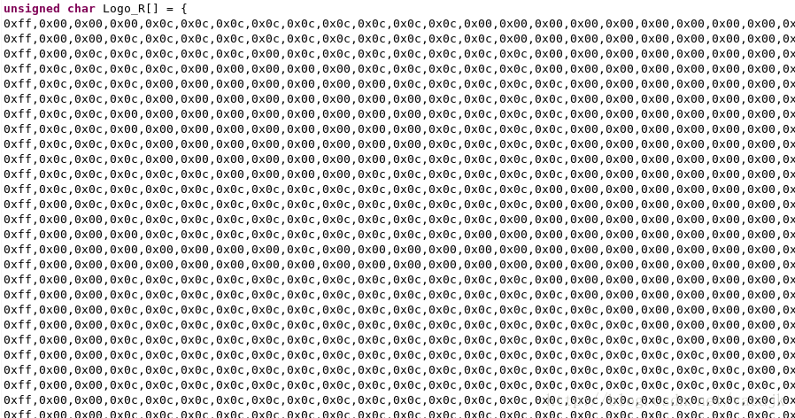
可以用python或者matlab生成这四个数组。这个logo功能是支持透明度的,所以效果还是不错的。
使用PS画一个logo的png文件,Matlab生成logo数组的代码:
%clear
clc;
clear;
%read image
[img,map,alpha] = imread('logo.png');
[h,w,dim] = size(img);
%split r,g,b,alpha
for i=1:h
    for j=1:w
        r(i,j) = img(i,j,1);
        g(i,j) = img(i,j,2);
        b(i,j) = img(i,j,3);
    end
end

%bug fixed
%vivado 2017.1 video mixer logo bug, see details in video_mixer IP bug.txt
%%
r_d = reshape(r', 1 ,w*h);
g_d = reshape(g', 1 ,w*h);
b_d = reshape(b', 1 ,w*h);
alpha_d = reshape(alpha', 1 ,w*h);
for i=2:w*h
    r_d_s(i) = r_d(i-1);
    g_d_s(i) = g_d(i-1);
    b_d_s(i) = b_d(i-1);
    alpha_d_s(i) = alpha_d(i-1);
end
r_d_s(1) = r_d(w*h);
g_d_s(1) = g_d(w*h);
b_d_s(1) = b_d(w*h);
alpha_d_s(1) = alpha_d(w*h);
r_r = reshape(r_d_s, w, h);
g_r = reshape(g_d_s, w, h);
b_r = reshape(b_d_s, w, h);
alpha_r = reshape(alpha_d_s, w, h);
r = r_r';
g = g_r';
b = b_r';
alpha = alpha_r';
%%

%write logo.c
fid = fopen('logo.c','wt');
fprintf(fid,'%s\n','/*');
fprintf(fid,'%s\n',' * logo.c');
fprintf(fid,'%s\n',' *');
fprintf(fid,'%s%d * %d\n',' *  LOGO size : ',h,w);
fprintf(fid,'%s%s\n',' * Created on : ',datestr(now));
fprintf(fid,'%s%s\n',' *       Tool : Matlab ',version);
fprintf(fid,'%s\n',' *     Author : Vacajk');
fprintf(fid,'%s\n',' */');
fprintf(fid,'\n');
%fprint array data
%red
fprintf(fid,'%s\n','unsigned char Logo_R[] = {');
for i=1:h
    for j=1:w
        fprintf(fid,'%s%02x,','0x',r(i,j));
    end
    fprintf(fid,'\n');
end
fprintf(fid,'%s\n','};');
fprintf(fid,'\n');
%green
fprintf(fid,'%s\n','unsigned char Logo_G[] = {');
for i=1:h
    for j=1:w
        fprintf(fid,'%s%02x,','0x',g(i,j));
    end
    fprintf(fid,'\n');
end
fprintf(fid,'%s\n','};');
fprintf(fid,'\n');
%blue
fprintf(fid,'%s\n','unsigned char Logo_B[] = {');
for i=1:h
    for j=1:w
        fprintf(fid,'%s%02x,','0x',b(i,j));
    end
    fprintf(fid,'\n');
end
fprintf(fid,'%s\n','};');
fprintf(fid,'\n');
%alpha
fprintf(fid,'%s\n','unsigned char Logo_A[] = {');
for i=1:h
    for j=1:w
        fprintf(fid,'%s%02x,','0x',alpha(i,j));
    end
    fprintf(fid,'\n');
end
fprintf(fid,'%s\n','};');
%close fid handle
fclose(fid);
video_mixer IP bug.txt
1.vivado 2017.1中 video mixer IP核在使用1 sample per clock时,logo会有bug。(因为官网说1spc时候没有验证,感觉是这里有问题)
logo的四个通道RGBA数组的第1个字节会跑到屏幕上的最后一个字节,第2个字节将作为首地址显示。
2.XVMIX_SCALE_FACTOR_4X能完全显示logo,但是1x和2x的时候前2列前1列数据会丢失,不知道什么原因
为了解决这个问题,在m文件中,将数组的最后一个字节和第一个字节对调。。这样就能确保显示的是正确的,不会错行显示
3 FRMBUF_WR测试
mix和tpg都测试完了,下面来测试frmbuf_wr ip的功能。
frmbuf_wr是连接到hdmi rx上的,前面已经解决了hpd信号的问题,我们电脑输入到MIZ7035的HDMI信号也已经被dvi2rgb IP的mmcms锁定,说明输入数据已经发过来了,只要把视频输入通路上的frmbuf_wr打通,图像数据就能够写到ddr中了。
为了方便,我直接将frmbuf_wr写入的帧地址与mix读取的帧地址写成一样的,这样通过HDMI RX接收到的视频经frmbuf_wr写入内存,就将能够直接通过mix、tpg最后到HDMI TX进行显示了。
当然其中有个问题是HDMI输入的视频必须要保证是1080p的视频,否则配置与实际不符的话会出问题。实际用的时候就需要根据hdmi_tx_ss中的vtc模块去检测输入图像了,然后去按照实际视频格式进行frmbuf_wr的配置以及显示输出的配置。
测试代码:
#define XVFRMBUFWR_BUFFER_BASEADDR (0x10000000)

int init_frmbufwr(void)
{

    u32 width, height;
    u32 StrideInBytes;
    XVidC_VideoStream VidStrm;
    XVidC_VideoTiming const *TimingPtr;

    int Status;
    Status = XVFrmbufWr_Initialize(&FrmbufWr, XPAR_V_DMA_SS_V_FRMBUF_WR_DEVICE_ID);
    if(Status != XST_SUCCESS) {
        xil_printf("ERROR:: Frame Buffer Write initialization failed\r\n");
        return(XST_FAILURE);
    }

    /* Stop Frame Buffers */
    XVFrmbufWr_Stop(&FrmbufWr);

    width       = 1920;
    height  = 1080;
    StrideInBytes = width*3;

    VidStrm.VmId           = XVIDC_VM_1080_60_P;
    VidStrm.ColorFormatId  = XVIDC_CSF_RGB;
    VidStrm.FrameRate      = XVIDC_FR_60HZ;
    VidStrm.IsInterlaced   = FALSE;
    VidStrm.ColorDepth     = XVIDC_BPC_8;
    VidStrm.PixPerClk      = XVIDC_PPC_1;
    VidStrm.Timing.HActive = width;
    VidStrm.Timing.VActive = height;
    TimingPtr = XVidC_GetTimingInfo(VidStrm.VmId);
    VidStrm.Timing = *TimingPtr;

    /* Configure  Frame Buffers */
    Status = XVFrmbufWr_SetMemFormat(&FrmbufWr, StrideInBytes, XVIDC_CSF_MEM_RGB8, &VidStrm);
    if(Status != XST_SUCCESS) {
        xil_printf("ERROR:: Unable to configure Frame Buffer Write\r\n");
        return(XST_FAILURE);
    }

    Status = XVFrmbufWr_SetBufferAddr(&FrmbufWr, (UINTPTR)0x10000000);
    if(Status != XST_SUCCESS) {
        xil_printf("ERROR:: Unable to configure Frame Buffer Write buffer address\r\n");
        return(XST_FAILURE);
    }

    /* Enable Interrupt */
    XVFrmbufWr_InterruptDisable(&FrmbufWr);

    /* Start Frame Buffers */
    XVFrmbufWr_Start(&FrmbufWr);

    xil_printf("INFO: FRMBUF configured\r\n");

    usleep(1000);
    XVFrmbufWr_DbgReportStatus(&FrmbufWr);

    return (XST_SUCCESS);
}
结果呢,等我写完代码进行测试时候,发现1080p的视频输入板子没有任何反应。看了一下原理图,HDMI RX的连接器使用的是交流耦合,然后进入FPGA的,但是耦合的电容后面的端接电阻没有焊接,那我手动焊接一下。
这里为什么要用交流耦合,是因为输入的TMDS信号与接入的FPGA HP BANK电压不能匹配,我们需要将TMDS信号转为LVDS信号才能输入HP BANK。
可以看一下这篇文档:交流耦合的优点
https://www.maximintegrated.com/cn/app-notes/index.mvp/id/4085
下图就是跟MIZ7035使用到的相同端接方法
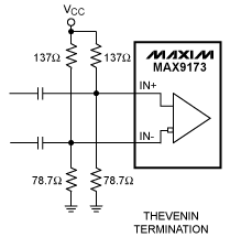
但是这里的VCC是3.3V,戴维宁等效电阻算出来是50欧。而我们的系统的VCC是1.8V,LVDS的共模电压为1.2V,根据戴维宁端接方法计算:
1.2V/1.8V=2/3=2R/(1R+2R) ->上拉电阻为1R、下拉电阻为2R
1R*2R/(1R+2R)=50
得到R=75,2R=150。
运气比较好,在电阻本里刚好找到了这两个阻值的电阻,焊接上去。
果然能够显示了,但是分辨率最高只能设置到1600*900。比这个值大的分辨率却不能正常显示,出现的是蓝色的条纹。还没分析出具体的原因。我用ila在线抓过dvi2rgb的信号,发现它的输出信号是有异常的,但是时钟看起来没有问题,看来问题就是出现在了这个ip中的某个地方。我试了将ac耦合电容换成0.2uf将lvds输入信号的摆浮稍微提高了一些,仍然没有效果。实在是不知道该怎么解决了。那就先用1600*900区测吧。
dvi2rgb中iodelay使用的是200MHz参考时钟,在1080p的时候serdes只有大约17个间隔,不知道是不是data信号的抖动过大导致不能锁住?可以去改成300MHz,但是改了后对低分辨率的可能又不支持了。
在这之中,还焊接过上拉10K下拉20K的方法,但是能够正常输入的分辨率支持的更低了,看来阻抗还是对整个系统有影响的。没学过高速电路,搞得人有点不太懂额。又问了老板,老板说他们AC耦合时候也能支持到1600*900,我当时没有试,那看来我后面接的戴维宁电阻没起到用处?
4 使用PL侧的DDR作为缓冲
前面代码在0x10000000位置创建了一个帧缓冲,是位于PS侧的DDR3。在SDK中使用搜索替换功能,将所有的0x10000000替换为0xC0000000,编译并重新下载。
HDMI输入输出依然OK,这就说明我们的PL DDR也是能作为图像缓存的,不错不错。
5 三重缓冲
输入输出打通了,但是只用了一块帧缓存。可以想一想,同时对一片区域的读写,当输入输出时钟频率完全同步时,可能有机会得到一个正常的视频显示。但实际是频率有略微差别的,所以输入输出会在每一时刻发生对一个字节数据的同时读写,这时候就会发生图像撕裂,或是一些其他的情况。因此需要使用多个缓存进行图像缓冲,实现读写不在同一个缓冲的目的。经常使用的缓冲数有2或3。图像处理时有可能CPU也去参与到其中,而CPU是带cache的,数据更新到DDR是有时间要求的,所以使用3重缓冲更为合适。这也只是我的经验,不同情况下可能有不同的结果。
这里说一下思路,具体实现等有空了再来做。
Xilinx的VDMA IP是带有多个缓冲自动切换功能的,但是毕竟没有mix IP好用。
为了同步,有以下几个方面需要进行处理:
- 视频输入是经过frmbuf_wr写进内存的,所以需要使用它的中断信号来对输入进行同步处理
- 视频输出是经过mix和tpg输出到外部显示器的,所以可以选择,我一般会用mix的中断来对输出进行同步处理
- 在该系统中,输出的高速时钟是通过板内外部100m时钟倍频得到的,而输出的高速时钟是PC给板子的。若只是一个输入输出显示的工程,这样做就可以了。但若是一个严格要求的视频处理卡(做到0丢帧),则需要将输入的高速时钟接入到HDMI TX通道中去,这样才能够保证两个通道达到完全意义上的同步。
3 总结
在MIZ7035开发板上完成了HDMI输入输出的设计,分析了开发板设计上的一些问题(这些问题还真的很费时间)。
给出了整个工程的驱动代码,大家可以参考使用。