CORDIC算法及其FPGA实现等学习总结
相关参考资料链接:
CORDIC算法计算正余弦
cordic算法的verilog实现及modelsim仿真
CORDIC算法--流水线结构
verilog实现基于Cordic算法的双曲函数计算
FPGA数字信号处理(十四)Vivado Cordic IP核计算arctan
xilinx cordic IP核的用法- arctan的算法
一、理论基础
CORDIC(Coordinate Rotation Digital Computer)算法即坐标旋转数字计算方法,是J.D.Volder1于1959年首次提出,主要用于三角函数、双曲线、指数、对数的计算。该算法通过基本的加和移位运算代替乘法运算,使得矢量的旋转和定向的计算不再需要三角函数、乘法、开方、反三角、指数等函数。
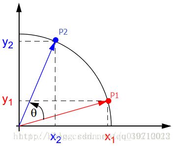
假设在xoy坐标系中有一个点P1(x1,y1),将P1点绕原点旋转θ角后得到点P2(x2,y2)。
可以得到P1和P2的关系,也就是CORDIC的几何原理部分。
x2 = x1cosθ – y1sinθ = cosθ(x1 – y1tanθ)
y2 = y1cosθ + x1sinθ = cosθ(y1 + x1tanθ)
二、MATLAB 程序实现
function v = cordic(beta,n)
% This function computes v = [cos(beta), sin(beta)] (beta in radians)
% using n iterations. Increasing n will increase the precision.

if beta < -pi/2 || beta > pi/2
    if beta < 0
        v = cordic(beta + pi, n);
    else
        v = cordic(beta - pi, n);
    end
    v = -v; % flip the sign for second or third quadrant
    return
end

% Initialization of tables of constants used by CORDIC
% need a table of arctangents of negative powers of two, in radians:
% angles = atan(2.^-(0:27));
angles =  [  ...
    0.78539816339745   0.46364760900081   0.24497866312686   0.12435499454676 ...
    0.06241880999596   0.03123983343027   0.01562372862048   0.00781234106010 ...
    0.00390623013197   0.00195312251648   0.00097656218956   0.00048828121119 ...
    0.00024414062015   0.00012207031189   0.00006103515617   0.00003051757812 ...
    0.00001525878906   0.00000762939453   0.00000381469727   0.00000190734863 ...
    0.00000095367432   0.00000047683716   0.00000023841858   0.00000011920929 ...
    0.00000005960464   0.00000002980232   0.00000001490116   0.00000000745058 ];
% and a table of products of reciprocal lengths of vectors [1, 2^-2j]:
Kvalues = [ ...
    0.70710678118655   0.63245553203368   0.61357199107790   0.60883391251775 ...
    0.60764825625617   0.60735177014130   0.60727764409353   0.60725911229889 ...
    0.60725447933256   0.60725332108988   0.60725303152913   0.60725295913894 ...
    0.60725294104140   0.60725293651701   0.60725293538591   0.60725293510314 ...
    0.60725293503245   0.60725293501477   0.60725293501035   0.60725293500925 ...
    0.60725293500897   0.60725293500890   0.60725293500889   0.60725293500888 ];
Kn = Kvalues(min(n, length(Kvalues)));

% Initialize loop variables:
v = [1;0]; % start with 2-vector cosine and sine of zero
poweroftwo = 1;
angle = angles(1);

% Iterations
for j = 0:n-1;
    if beta < 0
        sigma = -1;
    else
        sigma = 1;
    end
    factor = sigma * poweroftwo;
    R = [1, -factor; factor, 1];
    v = R * v; % 2-by-2 matrix multiply
    beta = beta - sigma * angle; % update the remaining angle
    poweroftwo = poweroftwo / 2;
    % update the angle from table, or eventually by just dividing by two
    if j+2 > length(angles)
        angle = angle / 2;
    else
        angle = angles(j+2);
    end
end

% Adjust length of output vector to be [cos(beta), sin(beta)]:
v = v * Kn;
return
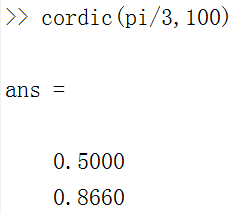
尝试在MATLAB中运行了下程序,结果如下:
三、Verilog HDL 实现
1、Verilog HDL源文件
module cordic
#(parameter DATA_WIDTH=8)
(
    input clk,
    input rst_n,
    input ena,
    input [DATA_WIDTH-1:0] phase_in,
    output reg [DATA_WIDTH-1:0] sin_out,
    output reg [DATA_WIDTH-1:0] cos_out,
    output reg [DATA_WIDTH-1:0] eps
);

localparam PIPELINE=8;

reg [DATA_WIDTH-1:0] phase_in_reg;
reg [DATA_WIDTH-1:0] x0,y0,z0;
reg [DATA_WIDTH-1:0] x1,y1,z1;
reg [DATA_WIDTH-1:0] x2,y2,z2;
reg [DATA_WIDTH-1:0] x3,y3,z3;
reg [DATA_WIDTH-1:0] x4,y4,z4;
reg [DATA_WIDTH-1:0] x5,y5,z5;
reg [DATA_WIDTH-1:0] x6,y6,z6;
reg [DATA_WIDTH-1:0] x7,y7,z7;

reg [1:0] quadrant [PIPELINE:0];
integer i;

always @(posedge clk,negedge rst_n)
begin
    if(!rst_n)
        phase_in_reg <= 8'b0;
    else
        if(ena)
        begin
            case(phase_in[7:6])
                2'b00: phase_in_reg <= phase_in;
                2'b01: phase_in_reg <= phase_in-8'h40;
                2'b10: phase_in_reg <= phase_in-8'h80;
                2'b11: phase_in_reg <= phase_in-8'hc0;
                default:;
            endcase
        end
end

always @ (posedge clk,negedge rst_n)
begin
    if(!rst_n)
        begin
            x0<=8'b0;
            y0<=8'b0;
            z0<=8'b0;
        end
    else
        if(ena)
        begin
            x0 <= 8'h4D;       //0.60725*2^7
            y0 <= 8'h00;
            z0 <= phase_in_reg;
        end
end

//level 1
always @ (posedge clk,negedge rst_n)
begin
    if(!rst_n)
    begin
        x1 <=8'b0;
        y1 <=8'b0;
        z1 <=8'b0;
    end
    else
    if(ena)
        if(z0[7]==1'b0)
        begin
            x1 <= x0-y0;
            y1 <= y0+x0;
            z1 <=z0-8'h20;//45deg
        end
        else
        begin
            x1<=x0+y0;
            y1<=y0-x0;
            z1<=z0+8'h20;
        end
end
//level 2
always @ (posedge clk,negedge rst_n)
begin
    if(!rst_n)
    begin
        x2 <=8'b0;
        y2 <=8'b0;
        z2 <=8'b0;
    end
    else
    if(ena)
        if(z1[7]==1'b0)
        begin
            x2 <= x1-{y1[DATA_WIDTH-1],y1[DATA_WIDTH-1:1]};
            y2 <= y1+{x1[DATA_WIDTH-1],x1[DATA_WIDTH-1:1]};
            z2 <=z1-8'h12;//26deg
        end
        else
        begin
            x2<= x1+{y1[DATA_WIDTH-1],y1[DATA_WIDTH-1:1]};
            y2<= y1-{x1[DATA_WIDTH-1],x1[DATA_WIDTH-1:1]};
            z2<= z1+8'h12;
        end
end
//level 3
always @ (posedge clk,negedge rst_n)
begin
    if(!rst_n)
    begin
        x3 <=8'b0;
        y3 <=8'b0;
        z3 <=8'b0;
    end
    else
    if(ena)
        if(z2[7]==1'b0)
        begin
            x3 <= x2-{{2{y2[DATA_WIDTH-1]}},y2[DATA_WIDTH-1:2]};
            y3 <= y2+{{2{x2[DATA_WIDTH-1]}},x2[DATA_WIDTH-1:2]};
            z3 <=z2-8'h09;//14deg
        end
        else
        begin
            x3<= x2+{{2{y2[DATA_WIDTH-1]}},y2[DATA_WIDTH-1:2]};
            y3<= y2-{{2{x2[DATA_WIDTH-1]}},x2[DATA_WIDTH-1:2]};
            z3<= z2+8'h09;
        end
end
//level 4
always @ (posedge clk,negedge rst_n)
begin
    if(!rst_n)
    begin
        x4 <=8'b0;
        y4 <=8'b0;
        z4 <=8'b0;
    end
    else
    if(ena)
        if(z3[7]==1'b0)
        begin
            x4 <= x3-{{3{y3[DATA_WIDTH-1]}},y3[DATA_WIDTH-1:3]};
            y4 <= y3+{{3{x3[DATA_WIDTH-1]}},x3[DATA_WIDTH-1:3]};
            z4 <= z3-8'h04;//7deg
        end
        else
        begin
            x4<= x3+{{3{y3[DATA_WIDTH-1]}},y3[DATA_WIDTH-1:3]};
            y4<= y3-{{3{x3[DATA_WIDTH-1]}},x3[DATA_WIDTH-1:3]};
            z4<= z3+8'h04;
        end
end
//level 5
always @ (posedge clk,negedge rst_n)
begin
    if(!rst_n)
    begin
        x5 <=8'b0;
        y5 <=8'b0;
        z5 <=8'b0;
    end
    else
    if(ena)
        if(z4[7]==1'b0)
        begin
            x5 <= x4-{{4{y4[DATA_WIDTH-1]}},y4[DATA_WIDTH-1:4]};
            y5 <= y4+{{4{x4[DATA_WIDTH-1]}},x4[DATA_WIDTH-1:4]};
            z5 <= z4-8'h02;//4deg
        end
        else
        begin
            x5<= x4+{{4{y4[DATA_WIDTH-1]}},y4[DATA_WIDTH-1:4]};
            y5<= y4-{{4{x4[DATA_WIDTH-1]}},x4[DATA_WIDTH-1:4]};
            z5<= z4+8'h02;
        end
end
//level 6
always @ (posedge clk,negedge rst_n)
begin
    if(!rst_n)
    begin
        x6 <=8'b0;
        y6 <=8'b0;
        z6 <=8'b0;
    end
    else
    if(ena)
        if(z5[7]==1'b0)
        begin
            x6 <= x5-{{5{y5[DATA_WIDTH-1]}},y5[DATA_WIDTH-1:5]};
            y6 <= y5+{{5{x5[DATA_WIDTH-1]}},x5[DATA_WIDTH-1:5]};
            z6 <= z5-8'h01;//2deg
        end
        else
        begin
            x6<= x5+{{5{y5[DATA_WIDTH-1]}},y5[DATA_WIDTH-1:5]};
            y6<= y5-{{5{x5[DATA_WIDTH-1]}},x5[DATA_WIDTH-1:5]};
            z6<= z5+8'h01;
        end
end
//level 7
always @ (posedge clk,negedge rst_n)
begin
    if(!rst_n)
    begin
        x7 <=8'b0;
        y7 <=8'b0;
        z7 <=8'b0;
    end
    else
    if(ena)
        if(z6[7]==1'b0)
        begin
            x7 <= x6-{{6{y6[DATA_WIDTH-1]}},y6[DATA_WIDTH-1:6]};
            y7 <= y6+{{6{x6[DATA_WIDTH-1]}},x6[DATA_WIDTH-1:6]};
            z7 <= z6-8'h00;//2deg
        end
        else
        begin
            x7<= x6+{{6{y6[DATA_WIDTH-1]}},y6[DATA_WIDTH-1:6]};
            y7<= y6-{{6{x6[DATA_WIDTH-1]}},x6[DATA_WIDTH-1:6]};
            z7<= z6+8'h00;
        end
end
//-------
always @ (posedge clk,negedge rst_n)
begin
    if(!rst_n)
        for(i=0;i<=PIPELINE;i=i+1)
            quadrant[i]<=2'b00;
    else
        if(ena)
            begin
                for(i=0;i
2、 测试仿真代码
// Generated on "05/21/2010 10:09:04"

// Verilog Test Bench template for design : cordic
//
// Simulation tool : ModelSim (Verilog)
//

`timescale 1 ps/ 1 ps
module cordic_tb;
// test vector input registers
reg arst;
reg clk;
reg clken;
reg [7:0] phase;
// wires
wire [7:0] cosine_out;
wire [7:0] eps_out;
wire [7:0] sine_out;
//
localparam coef=1000;
// assign statements (if any)
cordic i1 (
// port map - connection between master ports and signals/registers
    .rst_n(arst),
    .clk(clk),
    .ena(clken),
    .cos_out(cosine_out),
    .eps(eps_out),
    .phase_in(phase),
    .sin_out(sine_out)
);
initial
begin
  clk=0;
  clken=1;
  arst=0;
  #(30*coef) arst=1;
  #(10000*coef) $stop;
end
always #(5*coef) clk=~clk;
//
always @(negedge clk)
begin
  if(!arst)
    phase=0;
  else
    phase=phase+8'b00011001;;
end
endmodule
3、仿真波形
四、Cordic IP核
工程文件下载地址:https://download.csdn.net/download/weixin_37182342/10928163(ISE14.6)
在ISE软件中计算arctan,输入x_in = 16'b0010_1101_0100_0001,y_in = 16'b0010_1101_0100_0001,得到phase的值为:16'b0001_1001_0010_0010,也就是相位值为0.7853981,即为45°
16'b0001_1001_0010_0010转换成十进制数是6434,然后这个是Q13格式的,6434/2^13=0.7854003,也就是pi/4。
备注:Q格式相关资料
Q格式
Q格式


