图像处理之Canny边缘检测
图像处理之Canny 边缘检测
一:历史
Canny边缘检测算法是1986年有John F. Canny开发出来一种基于图像梯度计算的边缘
检测算法,同时Canny本人对计算图像边缘提取学科的发展也是做出了很多的贡献。尽
管至今已经许多年过去,但是该算法仍然是图像边缘检测方法经典算法之一。
二:Canny边缘检测算法
经典的Canny边缘检测算法通常都是从高斯模糊开始,到基于双阈值实现边缘连接结束
。但是在实际工程应用中,考虑到输入图像都是彩色图像,最终边缘连接之后的图像要
二值化输出显示,所以完整的Canny边缘检测算法实现步骤如下:
1. 彩色图像转换为灰度图像
2. 对图像进行高斯模糊
3. 计算图像梯度,根据梯度计算图像边缘幅值与角度
4. 非最大信号压制处理(边缘细化)
5. 双阈值边缘连接处理
6. 二值化图像输出结果
三:各步详解与代码实现
1. 彩色图像转灰度图像
根据彩色图像RGB转灰度公式:gray = R * 0.299 + G * 0.587 + B * 0.114
将彩色图像中每个RGB像素转为灰度值的代码如下:
int gray = (int) (0.299 * tr + 0.587 * tg + 0.114 * tb);2. 对图像进行高斯模糊
图像高斯模糊时,首先要根据输入参数确定高斯方差与窗口大小,这里我设置默认方
差值窗口大小为16x16,根据这两个参数生成高斯卷积核算子的代码如下:
		float kernel[][] = new float[gaussianKernelWidth][gaussianKernelWidth];
		for(int x=0; x
获取了高斯卷积算子之后,我们就可以对图像高斯卷积模糊,关于高斯图像模糊更详
细的解释可以参见这里:http://blog.csdn.net/jia20003/article/details/7234741实现
图像高斯卷积模糊的代码如下:
// 高斯模糊 -灰度图像
int krr = (int)gaussianKernelRadius;
for (int row = 0; row < height; row++) {
	for (int col = 0; col < width; col++) {
		index = row * width + col;
		double weightSum = 0.0;
		double redSum = 0;
		for(int subRow=-krr; subRow<=krr; subRow++)
		{
			int nrow = row + subRow;
			if(nrow >= height || nrow < 0)
			{
				nrow = 0;
			}
			for(int subCol=-krr; subCol<=krr; subCol++)
			{
				int ncol = col + subCol;
				if(ncol >= width || ncol <=0)
				{
					ncol = 0;
				}
				int index2 = nrow * width + ncol;
				int tr1 = (inPixels[index2] >> 16) & 0xff;
				redSum += tr1*kernel[subRow+krr][subCol+krr];
				weightSum += kernel[subRow+krr][subCol+krr];
			}
		}
		int gray = (int)(redSum / weightSum);
		outPixels[index] = gray;
	}
}
3. 计算图像X方向与Y方向梯度,根据梯度计算图像边缘幅值与角度大小
高斯模糊的目的主要为了整体降低图像噪声,目的是为了更准确计算图像梯度及边缘
幅值。计算图像梯度可以选择算子有Robot算子、Sobel算子、Prewitt算子等。关于
图像梯度计算更多的解释可以看这里:
http://blog.csdn.net/jia20003/article/details/7664777。
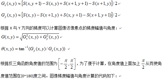
这里采用更加简单明了的2x2的算子,其数学表达如下:
// 计算梯度-gradient, X放与Y方向
data = new float[width * height];
magnitudes = new float[width * height];
for (int row = 0; row < height; row++) {
	for (int col = 0; col < width; col++) {
		index = row * width + col;
		// 计算X方向梯度
		float xg = (getPixel(outPixels, width, height, col, row+1) -
				getPixel(outPixels, width, height, col, row) +
				getPixel(outPixels, width, height, col+1, row+1) -
				getPixel(outPixels, width, height, col+1, row))/2.0f;
		float yg = (getPixel(outPixels, width, height, col, row)-
				getPixel(outPixels, width, height, col+1, row) +
				getPixel(outPixels, width, height, col, row+1) -
				getPixel(outPixels, width, height, col+1, row+1))/2.0f;
		// 计算振幅与角度
		data[index] = hypot(xg, yg);
		if(xg == 0)
		{
			if(yg > 0)
			{
				magnitudes[index]=90;
			}
			if(yg < 0)
			{
				magnitudes[index]=-90;
			}
		}
		else if(yg == 0)
		{
			magnitudes[index]=0;
		}
		else
		{
			magnitudes[index] = (float)((Math.atan(yg/xg) * 180)/Math.PI);
		}
		// make it 0 ~ 180
		magnitudes[index] += 90;
	}
}
在获取了图像每个像素的边缘幅值与角度之后
4. 非最大信号压制
信号压制本来是数字信号处理中经常用的,这里的非最大信号压制主要目的是实现边
缘细化,通过该步处理边缘像素进一步减少。非最大信号压制主要思想是假设3x3的
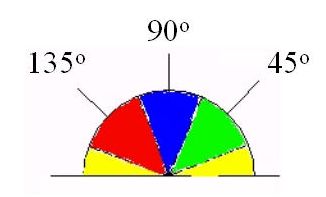
像素区域,中心像素P(x,y) 根据上一步中计算得到边缘角度值angle,可以将角度分
为四个离散值0、45、90、135分类依据如下:
其中黄色区域取值范围为0~22.5 与157.5~180
绿色区域取值范围为22.5 ~ 67.5
蓝色区域取值范围为67.5~112.5
红色区域取值范围为112.5~157.5
分别表示上述四个离散角度的取值范围。得到角度之后,比较中心像素角度上相邻
两个像素,如果中心像素小于其中任意一个,则舍弃该边缘像素点,否则保留。一
个简单的例子如下:

// 非最大信号压制算法 3x3
Arrays.fill(magnitudes, 0);
for (int row = 0; row < height; row++) {
	for (int col = 0; col < width; col++) {
		index = row * width + col;
		float angle = magnitudes[index];
		float m0 = data[index];
		magnitudes[index] = m0;
		if(angle >=0 && angle < 22.5) // angle 0
		{
			float m1 = getPixel(data, width, height, col-1, row);
			float m2 = getPixel(data, width, height, col+1, row);
			if(m0 < m1 || m0 < m2)
			{
				magnitudes[index] = 0;
			}
		}
		else if(angle >= 22.5 && angle < 67.5) // angle +45
		{
			float m1 = getPixel(data, width, height, col+1, row-1);
			float m2 = getPixel(data, width, height, col-1, row+1);
			if(m0 < m1 || m0 < m2)
			{
				magnitudes[index] = 0;
			}
		}
		else if(angle >= 67.5 && angle < 112.5) // angle 90
		{
			float m1 = getPixel(data, width, height, col, row+1);
			float m2 = getPixel(data, width, height, col, row-1);
			if(m0 < m1 || m0 < m2)
			{
				magnitudes[index] = 0;
			}
		}
		else if(angle >=112.5 && angle < 157.5) // angle 135 / -45
		{
			float m1 = getPixel(data, width, height, col-1, row-1);
			float m2 = getPixel(data, width, height, col+1, row+1);
			if(m0 < m1 || m0 < m2)
			{
				magnitudes[index] = 0;
			}
		}
		else if(angle >=157.5) // 跟零度是一致的,感谢一位网友发现了这个问题
		{
			float m1 = getPixel(data, width, height, col+1, row);
			float m2 = getPixel(data, width, height, col-1, row);
			if(m0 < m1 || m0 < m2)
			{
				magnitudes[index] = 0;
			}
		}
	}
}
1. 双阈值边缘连接
非最大信号压制以后,输出的幅值如果直接显示结果可能会少量的非边缘像素被包
含到结果中,所以要通过选取阈值进行取舍,传统的基于一个阈值的方法如果选择
的阈值较小起不到过滤非边缘的作用,如果选择的阈值过大容易丢失真正的图像边
缘,Canny提出基于双阈值(Fuzzy threshold)方法很好的实现了边缘选取,在实际
应用中双阈值还有边缘连接的作用。双阈值选择与边缘连接方法通过假设两个阈值
其中一个为高阈值TH另外一个为低阈值TL则有
a. 对于任意边缘像素低于TL的则丢弃
b. 对于任意边缘像素高于TH的则保留
c. 对于任意边缘像素值在TL与TH之间的,如果能通过边缘连接到一个像素大于
TH而且边缘所有像素大于最小阈值TL的则保留,否则丢弃。代码实现如下:
Arrays.fill(data, 0);
int offset = 0;
for (int row = 0; row < height; row++) {
	for (int col = 0; col < width; col++) {
		if(magnitudes[offset] >= highThreshold && data[offset] == 0)
		{
			edgeLink(col, row, offset, lowThreshold);
		}
		offset++;
	}
}private void edgeLink(int x1, int y1, int index, float threshold) {
int x0 = (x1 == 0) ? x1 : x1 - 1;
int x2 = (x1 == width - 1) ? x1 : x1 + 1;
int y0 = y1 == 0 ? y1 : y1 - 1;
int y2 = y1 == height -1 ? y1 : y1 + 1;
data[index] = magnitudes[index];
for (int x = x0; x <= x2; x++) {
for (int y = y0; y <= y2; y++) {
int i2 = x + y * width;
if ((y != y1 || x != x1)
&& data[i2] == 0
&& magnitudes[i2] >= threshold) {
edgeLink(x, y, i2, threshold);
return;
}
}
}
}6. 结果二值化显示 - 不说啦,直接点,自己看吧,太简单啦
// 二值化显示
for(int i=0; i 0 ? -1 : 0xff000000;
} package com.gloomyfish.filter.study;
import java.awt.image.BufferedImage;
import java.util.Arrays;
public class CannyEdgeFilter extends AbstractBufferedImageOp {
private float gaussianKernelRadius = 2f;
private int gaussianKernelWidth = 16;
private float lowThreshold;
private float highThreshold;
// image width, height
private int width;
private int height;
private float[] data;
private float[] magnitudes;
public CannyEdgeFilter() {
lowThreshold = 2.5f;
highThreshold = 7.5f;
gaussianKernelRadius = 2f;
gaussianKernelWidth = 16;
}
public float getGaussianKernelRadius() {
return gaussianKernelRadius;
}
public void setGaussianKernelRadius(float gaussianKernelRadius) {
this.gaussianKernelRadius = gaussianKernelRadius;
}
public int getGaussianKernelWidth() {
return gaussianKernelWidth;
}
public void setGaussianKernelWidth(int gaussianKernelWidth) {
this.gaussianKernelWidth = gaussianKernelWidth;
}
public float getLowThreshold() {
return lowThreshold;
}
public void setLowThreshold(float lowThreshold) {
this.lowThreshold = lowThreshold;
}
public float getHighThreshold() {
return highThreshold;
}
public void setHighThreshold(float highThreshold) {
this.highThreshold = highThreshold;
}
@Override
public BufferedImage filter(BufferedImage src, BufferedImage dest) {
width = src.getWidth();
height = src.getHeight();
if (dest == null)
dest = createCompatibleDestImage(src, null);
// 图像灰度化
int[] inPixels = new int[width * height];
int[] outPixels = new int[width * height];
getRGB(src, 0, 0, width, height, inPixels);
int index = 0;
for (int row = 0; row < height; row++) {
int ta = 0, tr = 0, tg = 0, tb = 0;
for (int col = 0; col < width; col++) {
index = row * width + col;
ta = (inPixels[index] >> 24) & 0xff;
tr = (inPixels[index] >> 16) & 0xff;
tg = (inPixels[index] >> 8) & 0xff;
tb = inPixels[index] & 0xff;
int gray = (int) (0.299 * tr + 0.587 * tg + 0.114 * tb);
inPixels[index] = (ta << 24) | (gray << 16) | (gray << 8)
| gray;
}
}
// 计算高斯卷积核
float kernel[][] = new float[gaussianKernelWidth][gaussianKernelWidth];
for(int x=0; x= height || nrow < 0)
{
nrow = 0;
}
for(int subCol=-krr; subCol<=krr; subCol++)
{
int ncol = col + subCol;
if(ncol >= width || ncol <=0)
{
ncol = 0;
}
int index2 = nrow * width + ncol;
int tr1 = (inPixels[index2] >> 16) & 0xff;
redSum += tr1*kernel[subRow+krr][subCol+krr];
weightSum += kernel[subRow+krr][subCol+krr];
}
}
int gray = (int)(redSum / weightSum);
outPixels[index] = gray;
}
}
// 计算梯度-gradient, X放与Y方向
data = new float[width * height];
magnitudes = new float[width * height];
for (int row = 0; row < height; row++) {
for (int col = 0; col < width; col++) {
index = row * width + col;
// 计算X方向梯度
float xg = (getPixel(outPixels, width, height, col, row+1) -
getPixel(outPixels, width, height, col, row) +
getPixel(outPixels, width, height, col+1, row+1) -
getPixel(outPixels, width, height, col+1, row))/2.0f;
float yg = (getPixel(outPixels, width, height, col, row)-
getPixel(outPixels, width, height, col+1, row) +
getPixel(outPixels, width, height, col, row+1) -
getPixel(outPixels, width, height, col+1, row+1))/2.0f;
// 计算振幅与角度
data[index] = hypot(xg, yg);
if(xg == 0)
{
if(yg > 0)
{
magnitudes[index]=90;
}
if(yg < 0)
{
magnitudes[index]=-90;
}
}
else if(yg == 0)
{
magnitudes[index]=0;
}
else
{
magnitudes[index] = (float)((Math.atan(yg/xg) * 180)/Math.PI);
}
// make it 0 ~ 180
magnitudes[index] += 90;
}
}
// 非最大信号压制算法 3x3
Arrays.fill(magnitudes, 0);
for (int row = 0; row < height; row++) {
for (int col = 0; col < width; col++) {
index = row * width + col;
float angle = magnitudes[index];
float m0 = data[index];
magnitudes[index] = m0;
if(angle >=0 && angle < 22.5) // angle 0
{
float m1 = getPixel(data, width, height, col-1, row);
float m2 = getPixel(data, width, height, col+1, row);
if(m0 < m1 || m0 < m2)
{
magnitudes[index] = 0;
}
}
else if(angle >= 22.5 && angle < 67.5) // angle +45
{
float m1 = getPixel(data, width, height, col+1, row-1);
float m2 = getPixel(data, width, height, col-1, row+1);
if(m0 < m1 || m0 < m2)
{
magnitudes[index] = 0;
}
}
else if(angle >= 67.5 && angle < 112.5) // angle 90
{
float m1 = getPixel(data, width, height, col, row+1);
float m2 = getPixel(data, width, height, col, row-1);
if(m0 < m1 || m0 < m2)
{
magnitudes[index] = 0;
}
}
else if(angle >=112.5 && angle < 157.5) // angle 135 / -45
{
float m1 = getPixel(data, width, height, col-1, row-1);
float m2 = getPixel(data, width, height, col+1, row+1);
if(m0 < m1 || m0 < m2)
{
magnitudes[index] = 0;
}
}
else if(angle >=157.5) // angle 0
{
float m1 = getPixel(data, width, height, col, row+1);
float m2 = getPixel(data, width, height, col, row-1);
if(m0 < m1 || m0 < m2)
{
magnitudes[index] = 0;
}
}
}
}
// 寻找最大与最小值
float min = 255;
float max = 0;
for(int i=0; i转载请务必注明出自本博客-gloomyfish


