arduino(3):使用ESP8266的 I2C接口,加上PCA9685 芯片控制舵机进行旋转
目录
- 前言
- 1,关于arduino esp8266 舵机
- 2,lib库安装
- 2,代码使用
- 3,总结
前言
相关arduino 全部分类:
https://blog.csdn.net/freewebsys/category_8799254.html
本文的原文连接是:
https://blog.csdn.net/freewebsys/article/details/104139532
未经博主允许不得转载。
博主地址是:http://blog.csdn.net/freewebsys
1,关于arduino esp8266 舵机
折腾半天开始计划直接使用 esp8266 驱动舵机。用gpio 模拟输出不可以。不知道为啥。
参考:
https://blog.csdn.net/qq_42807924/article/details/82229997
直接使用一个 PCA9685 就可以解决问题了。
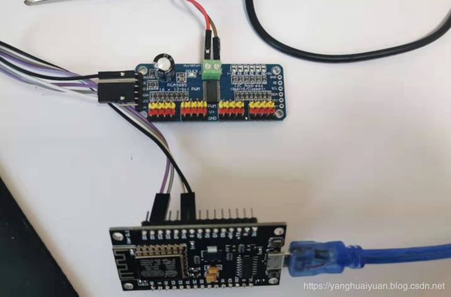
彩色的面板。
接线:
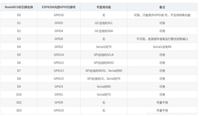
D1 GPIO5 I2C总线的SCL 【接入 PCA9685 的SLC 接口】。
D2 GPIO4 I2C总线的SDA 【接入 PCA9685 的SDA 接口】。

https://blog.csdn.net/dpjcn1990/article/details/92829865

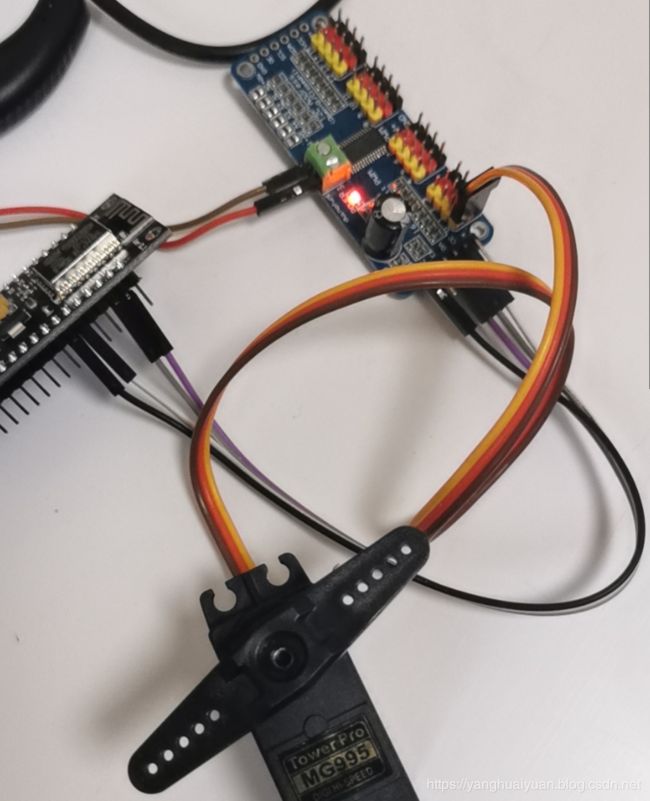
将舵机和 PCA9685 接入上:
【舵机棕色插头】 – 【PCA9685 的黑色针孔】
【舵机红色插头】 – 【PCA9685 的红色针孔】
【舵机黄色插头】 – 【PCA9685 的黄色针孔】
特别注意这个需要一个 5v 的供电。而开发板子,没有5v 输出,舵机使用 3.3 v 是驱动不起来的。
但是可以听到滋滋的响声。还是需要 5v 电压才可以。找个没有用的充电器。找到5v电压输入就行。
然后编写代码,支持参考那个哥们的。可以调动舵机旋转即可。
2,lib库安装
网络进行安装太慢了。
直接 到 arduino 目录下面找到 libraries/ 目录,然后把 github 地址:
https://github.com/adafruit/Adafruit-PWM-Servo-Driver-Library
直接下载,解压缩到 libraries 文件夹就可以了。
网络安装总觉得慢点。
2,代码使用
代码如下:
/***************************************************
  This is an example for our Adafruit 16-channel PWM & Servo driver
  Servo test - this will drive 16 servos, one after the other

  Pick one up today in the adafruit shop!
  ------> http://www.adafruit.com/products/815

  These displays use I2C to communicate, 2 pins are required to
  interface. For Arduino UNOs, thats SCL -> Analog 5, SDA -> Analog 4


  ****************************************************/

#include
#include

// called this way, it uses the default address 0x40
Adafruit_PWMServoDriver pwm = Adafruit_PWMServoDriver();
// you can also call it with a different address you want
//Adafruit_PWMServoDriver pwm = Adafruit_PWMServoDriver(0x41);
#define SERVOMIN  150 // this is the 'minimum' pulse length count (out of 4096)
#define SERVOMAX  600 // this is the 'maximum' pulse length count (out of 4096)

// our servo # counter
//uint8_t servonum = 0;

void setup() {
   Serial.begin(9600);
   Serial.println("16 channel Servo test!");

  pwm.begin();

   pwm.setPWMFreq(60);  // Analog servos run at ~60 Hz updates
 }

// you can use this function if you'd like to set the pulse length in seconds
// e.g. setServoPulse(0, 0.001) is a ~1 millisecond pulse width. its not precise!
 void setServoPulse(uint8_t n, double pulse) {
   double pulselength;//

   pulselength = 1000000;   // 1,000,000 us per second
   pulselength /= 60;   // 60 Hz
   Serial.print(pulselength); Serial.println(" us per period");
   pulselength /= 4096;  // 12 bits of resolution 12
   Serial.print(pulselength); Serial.println(" us per bit");
   pulse *= 1000;
   pulse /= pulselength;
   Serial.println(pulse);
   pwm.setPWM(n, 0, pulse);
}

void loop() {
   // Drive each servo one at a time
   //Serial.println(servonum);
     for (uint16_t pulselen = SERVOMIN; pulselen < SERVOMAX; pulselen++) {
     pwm.setPWM(0, 0, pulselen);
     pwm.setPWM(1, 0, pulselen);
     pwm.setPWM(2, 0, pulselen);
     pwm.setPWM(3, 0, pulselen);
     pwm.setPWM(4, 0, pulselen);
     pwm.setPWM(5, 0, pulselen);
     pwm.setPWM(6, 0, pulselen);
     pwm.setPWM(7, 0, pulselen);
     pwm.setPWM(8, 0, pulselen);
     pwm.setPWM(9, 0, pulselen);
     pwm.setPWM(10, 0, pulselen);
     pwm.setPWM(11, 0, pulselen);
     pwm.setPWM(12, 0, pulselen);
     pwm.setPWM(13, 0, pulselen);
     pwm.setPWM(14, 0, pulselen);
     pwm.setPWM(15, 0, pulselen);
   }
   delay(500);
   for (uint16_t pulselen = SERVOMAX; pulselen > SERVOMIN; pulselen--) {
     pwm.setPWM(0, 0, pulselen);
     pwm.setPWM(1, 0, pulselen);
     pwm.setPWM(2, 0, pulselen);
     pwm.setPWM(3, 0, pulselen);
     pwm.setPWM(4, 0, pulselen);
     pwm.setPWM(5, 0, pulselen);
     pwm.setPWM(6, 0, pulselen);
     pwm.setPWM(7, 0, pulselen);
     pwm.setPWM(8, 0, pulselen);
     pwm.setPWM(9, 0, pulselen);
     pwm.setPWM(10, 0, pulselen);
     pwm.setPWM(11, 0, pulselen);
     pwm.setPWM(12, 0, pulselen);
     pwm.setPWM(13, 0, pulselen);
     pwm.setPWM(14, 0, pulselen);
     pwm.setPWM(15, 0, pulselen);
   }
   delay(5000);

}
3,总结
arduino 现在已经非常的成熟了,是一个非常成熟的解决方案了。
这个麻烦的地方是找到映射关系即可。
ESP8266 的接口不多,找到一个配置表,发现了 I2C的 接口。然后按照接口进行链接就可以了。
本文的原文连接是:
https://blog.csdn.net/freewebsys/article/details/104139532
博主地址是:https://blog.csdn.net/freewebsys
![]()
