【FPGA】ODDR使用研究记录
这篇博文单讲ODDR,而不去深入理解和它相关的什么OLOGIC(花里胡哨):
为什么要花时间研究一下ODDR的工作原理呢?源于在之前的程序中用到了这个原语,虽疑惑为什么要用,但还是从用了之后有什么效果以及怎么用来下手吧。
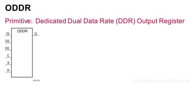
先看看ODDR的原语介绍:
ODDR是一个原理,全名叫:DedicatedDual Data Rate (DDR) Output Register,即专用双倍数据速率输出寄存器。
其有6个输入端口,一个输出端口。
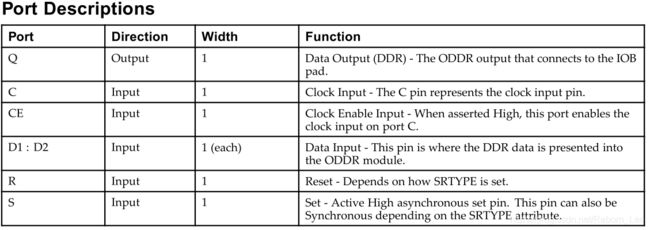
其端口含义如下:
C为时钟输入,根据此时钟来采样数据;
CE为时钟使能,高电平有效;
D1/D2为输入数据;
R和S分别为复位和置位,其设置与参数SRTYPE的设置有关。
在看看其参数:
第一个参数DDR_CLK_EDGE决定ODDR的操作模式,具体介绍在下面。
INIT决定输出初始化的值,而参数SRTYPE决定置位和复位的类型。
下面介绍操作模式:
ODDR有下面两种操作模式,
• OPPOSITE_EDGE mode
• SAME_EDGE mode
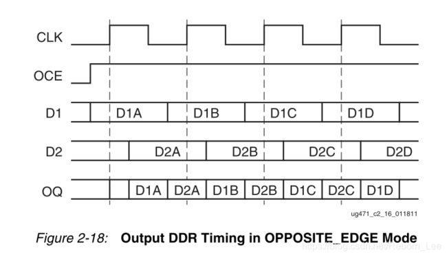
意思是,在OPPOSITE_EDGE mode中,在时钟C的上升沿采样D1,在下降沿采样D2。
时序图如下:
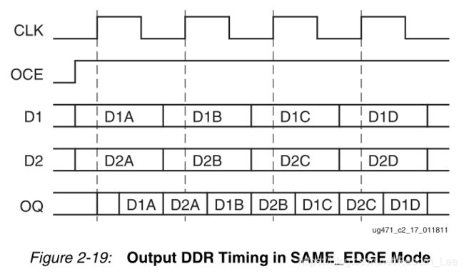
在SAME_EDGE mode中,在时钟的上升沿采样D1和D2。
时序图如下:
此原语的例化模板为:
// ODDR: Output Double Data Rate Output Register with Set, Reset
// and Clock Enable.
// 7 Series
// Xilinx HDL Libraries Guide, version 14.7
ODDR #(
.DDR_CLK_EDGE("OPPOSITE_EDGE"),// "OPPOSITE_EDGE" or "SAME_EDGE"
.INIT(1'b0), // Initial value of Q: 1'b0 or 1'b1
.SRTYPE("SYNC") // Set/Reset type: "SYNC" or "ASYNC"
) ODDR_inst (
.Q(Q), // 1-bit DDR output
.C(C), // 1-bit clock input
.CE(CE), // 1-bit clock enable input
.D1(D1), // 1-bit data input (positive edge)
.D2(D2), // 1-bit data input (negative edge)
.R(R), // 1-bit reset
.S(S) // 1-bit set
);
// End of ODDR_inst instantiation
默认的操作模式是OPPOSITE_EDGE mode,当如下方式使用这个原语时,其大致波形图如下:
ODDR #(
      .DDR_CLK_EDGE( "OPPOSITE_EDGE" ), // "OPPOSITE_EDGE" or "SAME_EDGE"
      .INIT( 1'b0 ),    // Initial value of Q: 1'b0 or 1'b1
      .SRTYPE( "SYNC" ) // Set/Reset type: "SYNC" or "ASYNC"
   ) ODDR_dsp_sriosgmiiclk (
      .Q( dsp_sriosgmiiclk_oddr ),   // 1-bit DDR output
      .C( dsp_sriosgmiiclk313m ),   // 1-bit clock input
      .CE( 1'b1 ), // 1-bit clock enable input
      .D1( 1'b1 ), // 1-bit data input (positive edge)
      .D2( 1'b0 ), // 1-bit data input (negative edge)
      .R( 1'b0 ),   // 1-bit reset
      .S( 1'b0 )     );  // 1-bit set
ODDR:
dsp_sriosgmiiclk313m 为输入时钟,而dsp_sriosgmiiclk_oddr 为输出时钟。
参考文献:
UG768 (v14.7) October 2, 2013
UG471 (v1.10) May 8, 2018
Xilinx原语ODDR概述和使用
Xilinx OLOGIC 资源
https://wavedrom.com/editor.html
https://blog.csdn.net/Reborn_Lee/article/details/81368861
https://www.cnblogs.com/lifei-chan/p/8653973.html


