HDLbits Exams/ece241 2013 q4
HDLbits Question 123
Exams/ece241 2013 q4

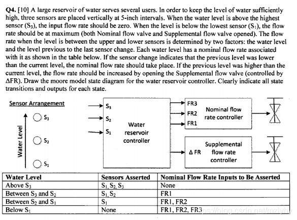
I reckon most of guys could read through instructions over that question so that I won’t do any explanations further (smile).
While I was trying to figure that question, I realized few points you might need to take care as well: each state of ‘s’ has either 1 or 0 status when flow rate would be as either nominal or supplemental scenarios, the total FSM is being either increasing water level or decreasing the water level.
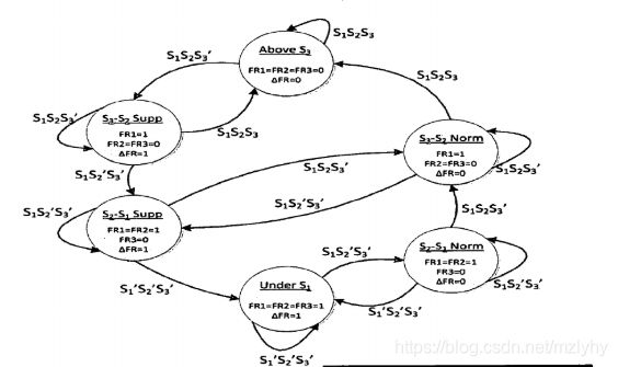
I saw there ain’t so much of pictures drawing the FSM, but a interesting thing is that quastion was from my college’s exam. I’m sharing a right FSM picture drawn by examiner.

This is pretty clear figure that explains how water sensors work in this case. Thus, I’m just going to put my own source code that might be written as a typical way including synchronous transition logic and state changing logic.
// top_module define
module top_module (
    input clk,
    input reset,
    input [3:1] s,
    output fr3,
    output fr2,
    output fr1,
    output dfr
);
//rename/define parameters in the case
    reg [3:0]state, next_state;
    reg [3:0] uns1, s2s1norm, s3s2norm, aboves3, s3s2supp, s2s1supp;
    //assign state values to each state name
    			//fr3 fr2 fr1 dfr
    assign uns1 = {1'b1,1'b1,1'b1,1'b1};
    assign s2s1norm = {1'b0,1'b1,1'b1,1'b0};
    assign s3s2norm = {1'b0,1'b0,1'b1,1'b0};
    assign aboves3 = {1'b0,1'b0,1'b0,1'b0};
    assign s3s2supp = {1'b0,1'b0,1'b1,1'b1};
    assign s2s1supp = {1'b0,1'b1,1'b1,1'b1};
    //fsm transition logic

    always@(*)begin

        case(state)
            uns1:
            if(s[1]&!s[2]&!s[3])begin
                	next_state = s2s1norm;

            end
            	  else next_state = uns1;

            s2s1norm:
            if(s[1]&s[2]&!s[3])begin
                		next_state = s3s2norm;end
            else if(s[1]&!s[2]&!s[3])begin
                next_state = s2s1norm; end
            else next_state = uns1;

            s3s2norm:
                if(s[1]&s[2]&s[3])begin
                    next_state = aboves3;end
            else if(s[1]&!s[2]&!s[3])begin
                next_state = s2s1supp;end
            else next_state = s3s2norm;

            aboves3:
                if(s[1]&s[2]&!s[3])begin
                    next_state = s3s2supp;end
            else next_state = aboves3;

            s3s2supp:
                if(s[1]&s[2]&s[3])begin
                    next_state = aboves3; end
            else if(s[1]&!s[2]&!s[3])begin
                next_state = s2s1supp; end
            else next_state = s3s2supp;

            s2s1supp:
                if(s[1]&s[2]&!s[3])begin
                    next_state = s3s2norm;end
            else if(!s[1]&!s[2]&!s[3])begin
                next_state = uns1;end
            else next_state = s2s1supp;

        endcase


    end
    //synchronous logic
    always@(posedge clk)begin

        if(reset)
            begin
            state <= uns1;

            end
        else
            begin
                state <= next_state;
            end

         end

    assign {fr3,fr2,fr1,dfr} = state;


endmodule