HDLbits代码记录一(1.Getting started & 2.1Basics)
此博用于学习记录,如果有错误,欢迎指正。
Problem sets
①getting started//输出1
module top_module( output one );
    assign one = 1;
endmodule
②output zero //输出0
module top_module( output zero);
    assign zero = 0;
endmodule
Verilog Language
Basics
①wire //连接out-in
注:中间绿色的连线不是wire,input和output才是wire

module top_module( input in, output out );
    assign out = in;
endmodule
②inverter//创建非门
module top_module( input in, output out );
assign out = ~ in;
endmodule
③And gate//创建与门
Assign statements will drive a logic level onto a wire.
assign语句是在wire上驱动逻辑(任何复杂的组合逻辑)。
a wire that has no drivers will have an undefined value (often treated as 0 when synthesizing hardware).wire没有被驱动的时候,是一个未知的值(但是在硬件综合中,往往被当作0)。

module top_module(
    input a,
    input b,
    output out );

assign out = a & b;

endmodule
④NOR gate//创建或非门
An assign statement is a continuous assignment because the output is “recomputed” whenever any of its inputs change, forever, much like a simple logic gate.
assign是连续赋值语句,当assign右边改变的时候,左边会立刻随着变动。

module top_module(
    input a,
    input b,
    output out );

    assign out = ~(a | b);

endmodule
NOR波形:
⑤XNOR gate//创建同或门

module top_module(
    input a,
    input b,
    output out );

    assign out = ~(a ^ b);

endmodule
波形:

⑥Declaring wires//声明线网类型
As circuits become more complex, you will need wires to connect internal components together. 随着电路变复杂,你将需要用wire把内部组件连接在一起。
Example:

module top_module (
    input in,              // Declare an input wire named "in"
    output out             // Declare an output wire named "out"
);

    wire not_in;           // Declare a wire named "not_in"

    assign out = ~not_in;  // Assign a value to out (create a NOT gate).
    assign not_in = ~in;   // Assign a value to not_in (create another NOT gate).

endmodule   // End of module "top_module"
Practice:
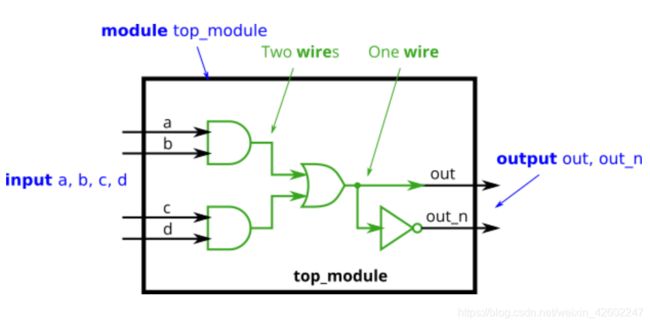
`default_nettype none
module top_module(
    input a,
    input b,
    input c,
    input d,
    output out,
    output out_n   );

wire one,two,three;

    assign out = one;
    assign out_n = ~one;
    assign one = two | three;
    assign two = a & b;
    assign three = c & d;

endmodule
注:out那里标注了"one wire"的绿线可以直接省略,用assign out_n = ~out,正确波形如下:

⑦7458
You may choose to use an assign statement to drive each of the output wires, or you may choose to declare (four) wires for use as intermediate signals.你可以使用assign语句直接驱动每个输出的方法;也可以用声明中间连线wire(4个)的方法来写。

module top_module (
    input p1a, p1b, p1c, p1d, p1e, p1f,
    output p1y,
    input p2a, p2b, p2c, p2d,
    output p2y );

    assign p1y = (p1a & p1b &p1c) | (p1d & p1e & p1f);
    assign p2y = (p2a & p2b) | (p2c & p2d);

endmodule
波形:
总结:
1.input和output都是wire
2.当assign右边变化时,左边立刻变化,是连续型赋值语句
3.组合逻辑多时,out有两种写法:声明多余的中间wire,或者直接用assign驱动。
4.assign感觉就是连线,左右两边都是output也可以。
不得不说,HDLBits对于Verilog新手真的非常友好,类型描述的非常清晰,解释的很透彻。
GitHub也上有人公布了部分代码,链接 :https://github.com/xiaop1/Verilog-Practice
官网HDLBits:https://hdlbits.01xz.net/wiki/Problem_sets#Verilog_Language