自适应波束形成(四)——Frost波束形成1
1 算法原理
LCMV波束形成器最优权向量的求解依赖于阵列接收数据的统计知识,即要计算自相关Rx。然而,实际应用中阵列接收数据的自相关是未知的或是时变的,此时约束自适应算法能用来逼近权向量,即Frost波束形成器。
首先,初始化权向量w[0] = C(CHC)-1f,它满足约束条件。然后以一个适当的比例系数朝Rxxw+Cλ 负梯度方向迭代,得到
w[n+1] = w[n] - µ(Rxxw[n] +Cλ[n])
既然w[n+1]满足CHw = f ,将其代入解得λ[n],然后代回上式,得到
w[n+1] = C(CHC)-1f +P(w[n]-µRxxw[n])
其中P=I- C(CHC)-1CH,I为单位矩阵。
由于不知二阶统计量 R xx,自相关矩阵可近似为 R xx≅ xx H。而 x H w[ n]恰是阵列第n次迭代的输出y[ n],因此Ftost波束形成器归结为w[0] = C(CHC)-1f
w[n+1] = C(CHC)-1f +P(w[n]-µy[n]x[n])
2 对模拟麦克风阵列语音进行增强
在matlab r2011a的toolbox的phased有波束形成相关的demo,demo之一代码如下:
%Define a Uniform Linear Array
%First we define a uniform linear array (ULA) to receive the signal.
%The array contains 10 omnidirectional microphones and the element spacing is 5 cm
hmic=phased.OmnidirectionalMicrophoneElement;
ha=phased.ULA(4,0.05,'Element',hmic);
c=340;                                       %sound speed,in m/s

%Simulate the Received Signals
load('twospeeches','speech1','speech2');
load('laughter','y');                       %The laughter is stored in variable y
y=2*y*(1:length(speech1));                   %Amplify and truncate
fs=8192;                                    %in Hz

wavwrite(speech1,fs,'speech1.wav');
wavwrite(speech2,fs,'speech2.wav');
ang1=[-30;0];
ang2=[60;10];
angInt=[20;0];

hCollector=phased.WidebandCollector('Sensor',ha,'PropagationSpeed',c,...
     'SampleRate',fs,'ModulateInput',false);
 sigSource=step(hCollector,[speech1 speech2 y],[ang1 ang2 angInt]);

 rs=RandStream.create('mt19937ar','Seed',2008);
 noisePwr=1e-4;                              %noise power
 sigNoise=sqrt(noisePwr)*randn(rs,size(sigSource));

 sigArray=sigSource+sigNoise;
 wavwrite(sigArray(:,3),fs,'sigArray.wav');

 %Plot channel 3
 plot(sigArray(:,3));
 xlabel('Time(sec)');ylabel('Amplitude(V)');
 title('Signal Received at Channal 3');ylim([-3 3]);

 %Listen to channal 3
 player=audioplayer(sigArray(:,3),fs);
 play(player);

 %Process with a Time Delay Beamformer
 angSteer=ang1;
 hbf=phased.TimeDelayBeamformer('SensorArray',ha,'SampleRate',fs,...
     'Direction',angSteer,'PropagationSpeed',c)

 cbfOut=step(hbf,sigArray);

 plot(cbfOut);
 xlabel('Time(Sec)');ylabel('Amplitude(V)');
 title('Time Delay Beamformer Output');ylim([-3 3]);

 player=audioplay(cbfOut,fs);
 play(player);

 agCbf=pow2db(mean((speech2+y).^2+noisePwr)/mean((cbfOut-speech1).^2))

 %Process with a Frost Beamdormer
 hbf=phased.FrostBeamformer('SensorArray',ha,'SampleRate',fs,...
     'PropagationSpeed',c,'WeightsOutputPort',true);
 %The beamformer may change its steering direction during processing
 hbf.DirectionSource='Input port';
 hbf.FilterLength=20;    %Set the length of FIR filter for each sensor to 20

 [FrostOut,w]=step(hbf,sigArray,ang1);

 plot(FrostOut);
 xlabel('Time(sec)');ylabel('Amplitude(V)');
 title('Frost Beamformer Output');ylim([-3 3]);

 player=audioplayer(FrostOut,fs);
 play(player);

 agFrost=pow2db(mean((speech2+y).^2+noisePwr)/mean((FrostOut-speech1).^2))

 %Use Diagonal Loading to Improve Robustness to the Frost Beamformer
 release(hbf);
 dir2=[50;20];               %Estimated steering direction
 FrostOut=step(hbf,sigArray,dir2);

 plot(FrostOut);
 xlabel('Time(sec)');ylabel('Amplitude(V)');
 title('Frost Beamformer Output');ylim([-3 3]);

 player=audioplayer(FrostOut,fs);
 play(player);

 agFrost2=pow2db(mean((speech1+y).^2+noisePwr)/mean((FrostOut-speech2).^2))

 release(hbf);
 hbf.DiagonalLoadingFactor=1e-3;    %Specify diagonal loading value
 FrostOut=step(hbf,sigArray,dir2);

 plot(FrostOut);
 xlabel('Time(sec)');ylabel('Amplitude(V)');
 title('Frost Beamformer Output');ylim([-3 3]);

 player=audioplayer(FrostOut,fs);
 play(player);

 agFrostDL=pow2db(mean((speech1+y).^2+noisePwr)/mean((FrostOut-speech2).^2))
首先定义一个均匀线性阵列,包含8个全向性麦克风阵元,阵元间距5cm,声速340m/s;然后模拟麦克风接收到的信号,语音1为一段男声,语音2为一段女声,采样率8192Hz,分别在-30o和60o,同时在20o有一段笑声作为干扰,并加上随机噪声作为本底噪声,用matlab中函数模拟产生一个39922*8的矩阵,每一列代表一个阵元接收到的混合声音信号。各信号如图1所示。
图1 各方向信号及本底噪声波形
然后编写C++代码,运用Frost波束形成器,分别对-30o方向男声语音1和60o方向女声语音2进行增强,混合语音、增强后语音1和增强后语音2的波形如图2所示。
图2 混合信号及增强后语音信号波形
由图2波形图可看出,编写的算法程序明显衰减了不希望的干扰及噪声,增强了期望语音信号,由增强后语音的听音效果可以听出增强效果很明显,能清楚地听到期望声音。
3 影响语音增强的因素
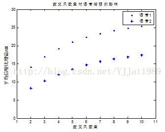
(1) 麦克风数量对语音增强效果的影响
运用上述方法在matlab中模拟产生麦克风阵列语音进行增强,各声音信号方向不变,保持阵元间距为5cm,采样率为8192Hz,语音1平均输入信噪比为-8.4949dB,语音2平均输入信噪比为-10.6588dB,将麦克风数量从10逐渐减小到2,计算两语音平均输出信噪比和平均信噪比增益,如图3所示。
图3 不同麦克风数量语音增强平均信噪比增益
由图3可知,在其他条件不变的情况下,随着麦克风数量的增多,平均信噪比增益增加;当麦克风数量增加到一定程度时,平均信噪比增益提升不明显。因而在实际应用中,在可接受的信噪比增益要求下,使用尽可能多的麦克风。
(2) 麦克风间距对语音增强效果的影响
与上面的仿真相似,保持麦克风数量为10个,采样率为8192Hz不变,将麦克风间距从1cm增加到20cm,计算两语音平均平均信噪比增益,如图4所示。图4 不同麦克风间距语音增强平均信噪比增益
由图4可知,在其他条件不变的情况下,随着麦克风间距的增加,平均信噪比增益先有所提升,然后又有所下降。不同语音信号的最佳麦克风间距不同,因而实际操作中选择的间距应使不同语音都有较大信噪比增益。
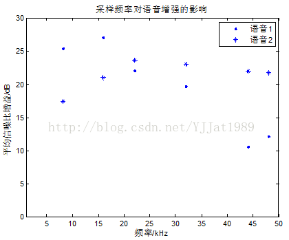
(3) 采样频率对语音增强效果的影响
最后,保持麦克风数量为10个,麦克风间距为5cm不变,分别仿真采样率为8.192kHz、16kHz、22.05kHz、32kHz、44.1kHz、48kHz时两语音的平均信噪比增益,如图5所示。
图5 不同采样率语音增强平均信噪比增益
由图5可看出,采样率稍大一些对语音增强效果有一定提升,采样率过大语音增强效果反而下降。不同信号由于频率不同,其最佳采样频率也不同,但一定要大于其最大频率的两倍。


