Python + Opencv2 实现轮廓提取、颜色标记,区域面积计算!
做图像处理时,会遇到这样一个场景:找到图像主体轮廓,这是其一,可能为了凸显轮廓,需要用指定的颜色进行标记;轮廓标记完可能任务还没有结束,还需对轮廓所勾勒的像素面积区域统计计算。
本篇文章的主要内容就是要解决上面场景遇到的三个问问题
- 找到图像主题轮廓;
- 用指定颜色对源图像进行轮廓标记;
- 计算轮廓中的主体;
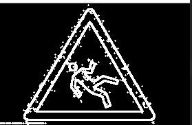
实验环境配置为 Python + Opencv 3.4, 处理的图像如下:
第一步,提取轮廓,Opencv 中的 findContours() 函数 可以直接提取轮廓,但对输入图像有一定要求
- 一,输入的图像必须是单通道,三通道不允许;
- 二,输入的图像数据类型需是 8UC1;否则程序会报错的,报错信息如下:
error: (-210) [start]FindContours supports only CV_8UC1 images when mode != CV_RETR_FLOODFILL otherwise supports CV_32SC1 images only in function cvStartFindContours_Impl
解决方法,在读取时加入下面这行代码进行数据格式转换,同时解决上面两个问题:
mat_img2 = cv2.imread(img_path,cv2.CV_8UC1)
- 三、输入的图像背景需是黑色的,否则轮廓提取失败,就以本次图像为例,如果直接提取效果如下:
图片最外层是一层黑色部分,所以最终结果就是标记最外层;对这类背景非黑色的图片做轮廓提取时,需要进行预处理:把背景变为黑色
提供一个简单办法,阈值化处理:设定一个阈值 Threshold 和一个指定值 OutsideValue ,当图像中像素满足某种条件(大于或小于设定的阈值时),像素值发生变化。
自适应阈值化分割
这里用到的是 Opencv 提供的自适应阈值分割算法,其函数格式为:
dst=cv2.adaptiveThreshold(src, maxValue, adaptiveMethod, thresholdType, blockSize, C)
-
src 需要分割的图像( adarray 类型);
-
maxValue ,满足条件是替换的像素值,等价于上面提到的 OutsideValue;
-
adaptiveMetheod: 自适应阈值分割算法,Opencv 中提供两种方法
1,ADAPTIVE_THRESH_MEAN_C : 最后的像素值 T ( x , y ) T(x,y) T(x,y) 为原像素值 ( x , y ) (x,y) (x,y) b l o c k s i z e ∗ b l o c k s i z e blocksize*blocksize blocksize∗blocksize 区域像素的平均值 C C C;
2,ADAPTIVE_THRESH_GAUSSIAN_C : 最后像素值 T ( x , y ) T(x,y) T(x,y) 为原像素值 ( x , y ) (x,y) (x,y) 附近 b l o c k s i z e ∗ b l o c k s i z e blocksize*blocksize blocksize∗blocksize 区域大小最小值 C C C;
- thresholdType 阈值分割方法,Opencv 提供了5 种;
1,THRESH_BINARY:
d s t ( x , y ) = { m a x v a l i f s r c ( x , y ) > t h r e s h 0 o t h e r w i s e dst(x,y) = \left\{ \begin{aligned} maxval & &if\ src(x,y)>thresh\\ 0 & & otherwise\\ \end{aligned} \right. dst(x,y)={ maxval0if src(x,y)>threshotherwise
2,THRESH_BINARY_INV:
d s t ( x , y ) = { 0 i f s r c ( x , y ) > t h r e s h m a x v a l o t h e r w i s e dst(x,y) = \left\{ \begin{aligned} 0 & &if\ src(x,y)>thresh\\ maxval & & otherwise\\ \end{aligned} \right. dst(x,y)={ 0maxvalif src(x,y)>threshotherwise
3,THRESH_TRUNC:
d s t ( x , y ) = { t h r e s h o l d i f s r c ( x , y ) > t h r e s h s r c ( x , y ) o t h e r w i s e dst(x,y)=\left\{ \begin{aligned} threshold & & if\ src(x,y)>thresh\\ src(x,y)& &otherwise\\ \end{aligned} \right. dst(x,y)={ thresholdsrc(x,y)if src(x,y)>threshotherwise
4,THRESH_TOZERO:
d s t ( x , y ) = { s r c ( x , y ) i f s r c ( x , y ) > t h r e s h 0 o t h e r w i s e dst(x,y)=\left\{\begin{aligned}src(x,y) & & if\ src(x,y)>thresh\\0& &otherwise\\\end{aligned}\right. dst(x,y)={ src(x,y)0if src(x,y)>threshotherwise
5,THRESH_TOZERO_INV;
d s t ( x , y ) = { 0 i f s r c ( x , y ) > t h r e s h s r c ( x , y ) o t h e r w i s e dst(x,y)=\left\{\begin{aligned}0 & & if\ src(x,y)>thresh\\src(x,y)& &otherwise\\\end{aligned}\right. dst(x,y)={ 0src(x,y)if src(x,y)>threshotherwise
- dst : 返回的阈值分割图像(是 ndarray 类型)
下面这行代码就是本次实验设置的参数:
dst = cv2.adaptiveThreshold(mat_img2,210,cv2.BORDER_REPLICATE,cv2.THRESH_BINARY_INV,3,10)
自适应阈值分割的结果:
轮廓提取
接下来就是进行轮廓提取了,用到的函数:
image, contours, hierarchy=cv2.findContours(image, mode, method)
- image 返回的图像,在 Opencv 4.0 之后就没有这个参数了;
- contours 标记的轮廓,以 list 形式存在,每个轮廓中都包含了轮廓像素的坐标向量;
- hierarchy 表示轮廓的继承关系,一般用不到;d
- image 后面image 表示需要标记轮廓的图像,以 ndarray 格式存在;
- mode 标记轮廓的模式,Opencv 提供了4种;
1,RETR_EXTERNAL;只提取整体外部轮廓;
2,RETR_LIST; 提取所有轮廓,不需要建立任何继承关系;
3, RETR_CCOMP ;提取所有轮廓,最后形成连个水平集,外面一个,内部一个;
4, RETR_TREE ;提取所有轮廓,构建等级关系(父子继承关系)
- method :轮廓近似点连接方式,例如一个长方形,可以由数百个点连接而成,单节省内存的方式就是找到四个角点即可;
- 其中前者为 CHAIN_APPROX_NONE 后者为 CHAIN_APPROX_SIMPLE
这里分别对 mode 设置不同的参数,一个设为 RETR_TREE (提取全部轮廓),一个设置 RETR_EXTRENAL (只提取最外部轮廓 );可以看一下提取轮廓效果:
RETR_TREE 结果:
RETR_EXTRENAL 结果:
是不是感受到了mode 不同导致轮廓的差距;一般只提取一个轮廓用 RETR_EXTRENAL,多个的话用 RETR_TREE;
轮廓标记
对轮廓颜色绘制,用到 的函数
cv2.drawContours(image, contours, contourIdx, color,thickness)
-
image 绘制轮廓的图像 ndarray 格式;
-
contours ,findContours 函数找到的轮廓列表;
-
contourIdx 绘制轮廓的索引数,取整数时绘制特定索引的轮廓,为负值时,绘制全部轮廓;
-
color 绘制轮廓所用到的颜色,这里需要提醒一下, 想使用 RGB 彩色绘制时,必须保证 输入的 image 为三通道,否则轮廓线非黑即白;
-
thickness ,用于绘制轮廓线条的宽度,取负值时将绘制整个轮廓区域;
以下就是分别取 thickness 为3(左)、-3(右) 绘制的结果
轮廓区域面积计算
最后计算轮廓面积,用到 cv2.contourArea(contour) 函数,里面的参数指的就是计算的轮廓
area = 0
for i in contours:
    area += cv2.contourArea(i)
print(area)


>>>16397.5 #最后结果
本篇文章用到的完整代码如下:
import cv2

img_path = "E:/data_ceshi/images.jpg"
#读取文件
mat_img = cv2.imread(img_path)
mat_img2 = cv2.imread(img_path,cv2.CV_8UC1)

#自适应分割
dst = cv2.adaptiveThreshold(mat_img2,210,cv2.BORDER_REPLICATE,cv2.THRESH_BINARY_INV,3,10)
#提取轮廓
img,contours,heridency = cv2.findContours(dst,cv2.RETR_EXTERNAL,cv2.CHAIN_APPROX_SIMPLE)
#标记轮廓
cv2.drawContours(mat_img,contours,-1,(255,0,255),3)

#计算轮廓面积
area = 0
for i in contours:
    area += cv2.contourArea(i)
print(area)

#图像show
cv2.imshow("window1",mat_img)
cv2.waitKey(0)


