Controller area network(bxCAN)
目录
一、Controller area network(bxCAN)
1.1、Introduction 介绍
1.2、bxCAN main features bxCAN 主要特性
1.2.1、Transmission 传动装置
1.2.2、Reception 接收
1.2.3、Time-triggered communication option 时间触发配置选项
1.2.4、Management 管理
二、bxCAN general description bxCAN普通描述
三、CAN 2.0B active core CAN2.0B 活动核心
3.1、Control, status and configuration registers 控制,状态和配置寄存器
3.2、Tx mailboxes 发送邮箱
3.3、Acceptance filters 验收滤波器
3.3.1、Receive FIFO
四、bxCAN operating modes 操作模式
4.1、Initialization mode 初始化模式
4.2、Normal mode 标准模式
4.3、Sleep mode (low-power) 睡眠模式(低电平)
五、Test mode 测试模式
5.1、Silent mode 静音模式
5.2、Loop back mode 线路循环模式
5.3、Loop back combined with silent mode 循环回结合沉默模式
六、Behavior in debug mode 调试模式下的行为
七、bxCAN functional description bxCAN功能描述
7.1、Transmission handling 传输处理
7.2、Time triggered communication mode 时间触发通信模式
7.3、Reception handling 接收处理
7.3.1、Valid message 有效的消息
7.3.2、FIFO management FIFO管理
7.3.3、Overrun 超出限度
7.4、Identifier filtering 标识符过滤
7.4.1、Scalable width 可伸缩的宽度
7.4.2、Mask mode 蒙版模式
7.4.3、Identifier list mode 标识符列表模式
7.4.4、Filter bank scale and mode configuration滤波器组规模和模式配置
7.4.5、Filter match index 过滤匹配指数
7.4.6、过滤器优先级规则 Filter priority rules
7.5、Message storage 消息存储
7.5.1、Transmit mailbox 邮箱传输
7.5.2、Receive mailbox 接收邮箱
7.6、Error management 错误管理
7.6.1、Bus-Off recovery 总线关闭复苏
7.7、Bit timing 位定时
八、bxCAN interrupts
九、CAN 寄存器 CAN registers
9.1、Register access protection 寄存器访问保护
9.2、CAN control and status registers CAN控制和状态寄存器
9.2.1、CAN master control register (CAN_MCR) CAN主控制寄存器
9.2.2、CAN master status register (CAN_MSR) CAN主状态寄存器
9.2.3、CAN transmit status register(CAN_TSR)
9.2.4、CAN receive FIFO 0 register(CAN_RF0R)
9.2.5、CAN receive FIFO 1 register(CAN_RF1R)
9.2.6、CAN interrupt enable register(CAN_IER)
9.2.7、CAN error status register(CAN_ESR)
9.2.8、CAN bit timing(定时) register(CAN_BTR)
9.3、CAN mailbox registers
9.3.1、 CAN TX mailbox identifier register (CAN_TIxR) (x = 0..2) CAN TX邮箱标识符寄存器(CAN_TIxR) (x = 0..2)
9.3.2、CAN mailbox data length control and time stamp register(CAN_TDTxR) (x = 0..2)邮箱数据长度可以控制和时间戳寄存器(CAN_TDTxR) (x = 0..2)
9.3.3、CAN mailbox data low register (CAN_TDLxR) (x = 0..2) CAN邮箱数据低寄存器
9.3.4、CAN mailbox data high register (CAN_TDHxR) (x = 0..2)
9.3.5、CAN receive FIFO mailbox identifier register (CAN_RIxR) (x = 0..1)能接收FIFO寄存器的邮箱标识符
9.3.6、CAN receive FIFO mailbox data length control and time stamp register (CAN_RDTxR) (x = 0..1)
9.3.7、CAN receive FIFO mailbox data low register (CAN_RDLxR) (x = 0..1)
9.3.8、CAN receive FIFO mailbox data high register (CAN_RDHxR) (x = 0..1)
9.4、CAN filter( 过滤器;滤波器) registers
9.4.1、CAN filter master register (CAN_FMR)
9.4.2、CAN filter mode register (CAN_FM1R)
9.4.3、CAN filter scale register (CAN_FS1R)
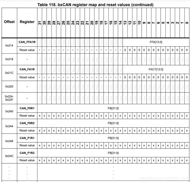
9.4.4、CAN filter FIFO assignment register (CAN_FFA1R)
9.4.5、CAN filter activation register (CAN_FA1R)
9.4.6、Filter bank i register x (CAN_FiRx) (i = 0..13, x = 1, 2)
9.5、bxCAN register map
一、Controller area network(bxCAN)
This section applies to STM32F042, STM32F072 and STM32F09x devices only
这一部分仅应用于STM32F042, STM32F072 和STM32F09x设备
1.1、Introduction 介绍
The Basic Extended CAN peripheral, named bxCAN, interfaces the CAN network. It supports the CAN protocols version 2.0A and B. It has been designed to manage a high number of incoming messages efficiently with a minimum CPU load. It also meets the priority requirements for transmit messages
基本扩展CAN外设,名为bxCAN,接口CAN网络,支持CAN协议版本CAN2.0A 和CAN2.0B,它被设计成以最小的CPU负载有效地管理大量传入消息。同时满足了报文传输的优先级要求。
For safety-critical applications, the CAN controller provides all hardware functions for supporting the CAN Time Triggered Communication option.
对于安全关键的应用,CAN控制器提供支持CAN时间触发通信选项的所有硬件功能。
1.2、bxCAN main features bxCAN 主要特性
- Supports CAN protocol version 2.0 A,B Active。 支持CAN协议版本CAN2.0A,CAN2.0B
- Bit rates up to 1Mbit/s 比特率可达1Mbit/s
- Supports the Time Triggered Communication option 支持时间触发通信选项
1.2.1、Transmission 传动装置
- Three transmit mailboxes 三个发送邮箱
- Configurable transmit priority 可配置的发送优先级
- Time Stamp on SOF transmission SOF传输的时间戳
1.2.2、Reception 接收
- Two receive FIFOs with three stages 三个阶段FIFOs两次接收
- Scalable filter banks:– 14 filter banks 可伸缩的滤波器组 14个滤波器
- Identifier list feature 标识符列表功能
- Configurable FIFO overrun 可配置的FIFO溢出
- Time Stamp on SOF reception 接待的时间戳
1.2.3、Time-triggered communication option 时间触发配置选项
- Disable automatic retransmission mode 禁用自动重传模式
- 16-bit free running timer 16位自由的运行计时器
- Time Stamp sent in last two data bytes 在最后两个数据字节中发送的时间戳
1.2.4、Management 管理
- maskable interrupts 可屏蔽中断
- Software-efficient mailbox mapping at a unique address space 软件高效的邮箱映射在一个唯一的地址空间
二、bxCAN general description bxCAN普通描述
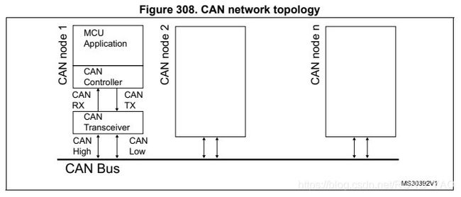
In today’s CAN applications, the number of nodes in a network is increasing and often several networks are linked together via gateways. Typically the number of messages in the system (and thus to be handled by each node) has significantly increased. In addition to the application messages, Network Management and Diagnostic messages have been introduced.
现在CAN应用,网络中的节点数量不断增加,通常几个网络通过网关连接在一起。通常,系统中的消息数量(因此由每个节点处理)显著增加。除应用消息外,还介绍了网络管理和诊断消息。
- An enhanced(提高) filtering(过滤) mechanism is required to handle each type of message.Furthermore, application tasks require more CPU time, therefore real-time constraints(约束) caused by message reception have to be reduced(简化的).
需要一种增强的过滤机制来处理每种类型的消息,此外,应用程序任务需要更多的CPU时间,因此,必须减少接收消息所带来的实时性限制。
- A receive FIFO scheme (方案)allows(认可,允许) the CPU to be dedicated(专用的) to application tasks for a long time period(期间) without(没有,不会) losing(丢失) messages.
接收FIFO方案允许CPU在很长一段时间内专门用于应用程序任务,而不会丢失消息。
- The standard HLP (Higher Layer Protocol) based on standard CAN drivers requires an efficient interface to the CAN controller.
基于标准CAN驱动程序的标准HLP(高层协议)需要一个到CAN控制器的有效接口。
topology 拓扑学
三、CAN 2.0B active core CAN2.0B 活动核心
The bxCAN module(模块) handles the transmission(传输) and the reception(接收) of CAN messages fully autonomously(自主处理). Standard identifiers (11-bit) and extended identifiers (29-bit) are fully
supported by hardware.
bxCAN模块完全自主地处理CAN消息的传输和接收。硬件完全支持标准标识符(11位)和扩展标识符(29位)。
3.1、Control, status and configuration registers 控制,状态和配置寄存器
The application uses these registers to:
应用程序使用这些寄存器
- Configure CAN parameters, e.g. baud rate 置CAN参数,例如波特率
- Request transmissions 请求传输
- Handle receptions 处理接收
- Manage interrupts 管理中断
- Get diagnostic information 获取诊断信息
3.2、Tx mailboxes 发送邮箱
Three transmit mailboxes are provided(提供) to the software for setting up messages. The transmission Scheduler decides which mailbox has to be transmitted first.
软件提供三个传输邮箱,用于设置消息。传输调度程序决定首先要传输哪个邮箱。
3.3、Acceptance filters 验收滤波器
The bxCAN provides up to 14 scalable/configurable identifier filter banks, for selecting the incoming messages, that the software needs and discarding the others
bxCAN提供多达14个可扩展/可配置的标识符过滤库,用于选择软件需要的传入消息并丢弃其他消息。
3.3.1、Receive FIFO
Two receive FIFOs are used by hardware to store the incoming messages. Three complete messages can be stored in each FIFO. The FIFOs are managed completely by hardware.
硬件使用两个receive fifo来存储传入消息。每个FIFO中可以存储三条完整的消息。fifo完全由硬件来管理。
四、bxCAN operating modes 操作模式
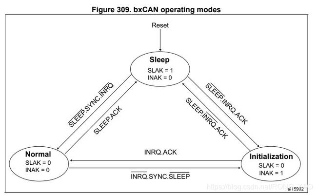
- bxCAN has three main operating modes: initialization, normal and Sleep. After a hardware reset, bxCAN is in Sleep mode to reduce(减少) power(电力) consumption (消耗)and an internal (内部)pullup (上拉)is active on CANTX. The software requests bxCAN to enter(进入) initialization or Sleep mode by setting the INRQ or SLEEP bits in the CAN_MCR register. Once the mode has been entered, bxCAN confirms(证实) it by setting the INAK or SLAK bits in the CAN_MSR register and the internal pull-up is disabled. When neither(不确定) INAK nor SLAK are set, bxCAN is in normal mode. Before entering normal mode bxCAN always has to synchronize on the CAN bus. To synchronize, bxCAN waits until the CAN bus is idle, this means(意味) 11 consecutive recessive bits have been monitored on CANRX
bxCAN 有三个主要的操作模式:初始化,标准和睡眠,硬件复位后,bxCAN是在睡眠模式,以减少电力消耗和内部上拉是有效的CANTX(CAN发送),软件需要bxCAN进入初始化或睡眠模式设置CAN_MCR寄存器的INRQ或SLEEP位,一旦进入模式,bxCAN通过设置CAN_MSR寄存器中的INAK或SLAK位来确认它,并且内部上拉被禁用。当INAK和SLAK都不确定时,bxCAN进入标准模式,在进入正常模式之前,bxCAN总是必须在CAN总线上同步。为了同步,bxCAN等待,直到CAN总线空闲,这意味着CANRX上已经监视了11个连续的隐性位。
4.1、Initialization mode 初始化模式
- The software initialization can be done(完成的) while the hardware is in Initialization mode. To enter this mode the software sets the INRQ bit in the CAN_MCR register and waits until the hardware has confirmed the request by setting the INAK bit in the CAN_MSR register.
软件初始化可以在硬件处于初始化模式时完成。为了进入这种模式,软件在CAN_MCR寄存器中设置INRQ位,并等待直到硬件通过在CAN_MSR寄存器中设置INAK位确认请求。
- To leave(离开) Initialization mode, the software clears the INQR bit. bxCAN has left Initialization mode once the INAK bit has been cleared by hardware
如果要离开初始化模式,软件会清除INQR位。一旦INAK位被硬件清除,bxCAN将离开初始化模式。
- While in Initialization Mode, all message transfers to and from the CAN bus are stopped and the status of the CAN bus output CANTX is recessive (high).
当在初始化模式,所有的消息传输和CAN总线是停止状态的CAN总线输出CANTX是隐性的(高)。
- Entering Initialization Mode does not change any of the configuration registers.
进入初始化模式不会改变任何配置寄存器
- To initialize the CAN Controller, software has to set up the Bit Timing (CAN_BTR) and CAN options (CAN_MCR) registers.
为了初始化CAN控制器,软件必须设置位定时(CAN_BTR)和CAN选项(CAN_MCR)寄存器。
- To initialize the registers associated with the CAN filter banks (mode, scale, FIFO assignment, activation and filter values), software has to set the FINIT bit (CAN_FMR). Filter initialization also can be done outside the initialization mode.
为了初始化与CAN滤波器组相关的寄存器(模式、规模、FIFO分配、激活和滤波器值),软件必须设置FINIT位(CAN_FMR)。过滤器初始化也可以在初始化模式之外完成。
note:
- When FINIT=1, CAN reception is deactivated(失效的). 当EINIT=1时,CAN接收失效
- The filter values also can be modified by deactivating the associated filter activation bits (in the CAN_FA1R register). 还可以通过取消激活相关的过滤器激活位(在CAN_FA1R寄存器中)来修改过滤器值
- If a filter bank is not used, it is recommended to leave it non active (leave the corresponding FACT bit cleared). 如果没有使用过滤器组,建议将其保持为非活动状态(保留相应的过滤器组清除)。
- For code example refer to the Appendix section
/* (1) Enter CAN init mode to write the configuration */
/* (2) Wait the init mode entering */
/* (3) Exit sleep mode */
/* (4) Loopback mode, set timing to 1Mb/s: BS1 = 4, BS2 = 3,
 prescaler = 6 */
/* (5) Leave init mode */
/* (6) Wait the init mode leaving */
/* (7) Enter filter init mode, (16-bit + mask, filter 0 for FIFO 0) */
/* (8) Acivate filter 0 */
/* (9) Set the Id and the mask (all bits of standard id care */
/* (10) Leave filter init */
/* (11) Set FIFO0 message pending IT enable */
CAN->MCR |= CAN_MCR_INRQ; /* (1) */
while ((CAN->MSR & CAN_MSR_INAK) != CAN_MSR_INAK) /* (2) */
{
 /* add time out here for a robust application */
}
CAN->MCR &=~ CAN_MCR_SLEEP; /* (3) */
CAN->BTR |= CAN_BTR_LBKM | 2 << 20 | 3 << 16 | 5 << 0; /* (4) */
CAN->MCR &=~ CAN_MCR_INRQ; /* (5) */
while ((CAN->MSR & CAN_MSR_INAK) == CAN_MSR_INAK) /* (6) */
{
 /* add time out here for a robust application */
}
CAN->FMR |= CAN_FMR_FINIT; /* (7) */
CAN->FA1R |= CAN_FA1R_FACT0; /* (8) */
CAN->sFilterRegister[0].FR1 = CAN_ID << 5 | 0xFF70U << 16; /* (9) */
CAN->FMR &=~ CAN_FMR_FINIT; /* (10) */
CAN->IER |= CAN_IER_FMPIE0; /* (11) */
4.2、Normal mode 标准模式
- Once the initialization is complete, the software must request the hardware to enter Normal mode to be able to synchronize on the CAN bus and start reception and transmission.
初始化完成,软件必须要求硬件进入标准模式才能同步在CAN总线上启动接收和传输。
- The request to enter Normal mode is issued by clearing the INRQ bit in the CAN_MCR register. The bxCAN enters Normal mode and is ready to take part in bus activities when it has synchronized with the data transfer on the CAN bus. This is done by waiting for the occurrence of a sequence of 11 consecutive recessive bits (Bus Idle state). The switch to Normal mode is confirmed by the hardware by clearing the INAK bit in the CAN_MSR register.
进入正常模式的请求是通过清除CAN_MCR寄存器中的INRQ位发出的,当与CAN总线上的数据传输同步后,bxCAN进入正常模式并准备好参与总线活动。这是通过等待一个由11个连续的隐性比特组成的序列(总线空闲状态)来完成的。切换到正常模式由硬件通过清除CAN_MSR寄存器中的INAK位来确认。
- The initialization of the filter values is independent from Initialization Mode but must be done while the filter is not active (corresponding FACTx bit cleared). The filter scale and mode configuration must be configured before entering Normal Mode.
过滤器值的初始化独立于初始化模式,但必须在过滤器未激活时进行(相应的FACTx位被清除)。在进入普通模式之前,必须先配置过滤规模和模式配置。
4.3、Sleep mode (low-power) 睡眠模式(低电平)
- To reduce power consumption, bxCAN has a low-power mode called Sleep mode. This mode is entered on software request by setting the SLEEP bit in the CAN_MCR register. In this mode, the bxCAN clock is stopped, however(但是) software can still access the bxCAN mailboxes.
减少耗电量,bxCAN有一种低功耗模式,叫做睡眠模式。在软件请求时,通过在CAN_MCR寄存器中设置睡眠位进入此模式。在这种模式下,bxCAN时钟是停止的,但是软件仍然可以访问bxCAN邮箱。
- If software requests entry to initialization mode by setting the INRQ bit while bxCAN is in Sleep mode, it must also clear the SLEEP bit.
如果软件请求进入初始模式,设置INRQ位,它必须清除SLEEP位。
- bxCAN can be woken up(唤醒) (exit Sleep mode退出睡眠模式) either(或者) by software clearing the SLEEP bit or on detection(检测) of CAN bus activity.
bxCAN可以被唤醒(退出睡眠模式)或者通过软件清除睡眠位或检测到can总线活动
- On CAN bus activity detection, hardware automatically(自动地) performs(执行) the wakeup sequence(序列) by clearing the SLEEP bit if the AWUM bit in the CAN_MCR register is set. If the AWUM bit is cleared, software has to clear the SLEEP bit when a wakeup interrupt occurs(重视), in order to exit from Sleep mode.
在检测CAN总线活动上,果设置了CAN_MCR寄存器中的AWUM位,硬件会通过清除睡眠位自动执行唤醒序列。如果AWUM位被清除,软件必须在唤醒中断发生时清除睡眠位,以便退出睡眠模式。
note:If the wakeup interrupt is enabled (WKUIE bit set in CAN_IER register) a wakeup interrupt will be generated(产生,生成) on detection of CAN bus activity, even if the bxCAN automatically performs the wakeup sequence.
如果唤醒中断被启用(在CAN_IER寄存器中设置WKUIE位),一个唤醒中断将在检测到CAN总线活动时生成,即使bxCAN自动执行唤醒序列。
- After the SLEEP bit has been cleared, Sleep mode is exited once bxCAN has synchronized with the CAN bus, refer to Figure 309: bxCAN operating modes. The Sleep mode is exited once the SLAK bit has been cleared by hardware.
SLEEP位被清除后,睡眠模式退出bxCAN同步到CAN总线,一旦硬件清除了SLAK位,就退出休眠模式。
- ACK = The wait state during which hardware confirms a request by setting the INAK or SLAK bits in the CAN_MSR register
- SYNC = The state during which bxCAN waits until the CAN bus is idle, meaning 11 consecutive recessive bits have been monitored on CANRX
- 在等待状态中,硬件通过设置INAK或SLAK位来确认请求CAN_MSR寄存器
- YNC = bxCAN等待直到CAN总线空闲的状态,这意味着CANRX上已经连续监视了11个隐性位
五、Test mode 测试模式
- Test mode can be selected by the SILM and LBKM bits in the CAN_BTR register. These bits must be configured while bxCAN is in Initialization mode. Once test mode has been selected, the INRQ bit in the CAN_MCR register must be reset to enter Normal mode.
测试模式能通过CAN_BTR寄存器选择SILM和LBKM位。这些位必须在bxCAN处于初始化模式时配置。一旦选择了测试模式,必须重置CAN_MCR寄存器中的INRQ位以进入正常模式。
5.1、Silent mode 静音模式
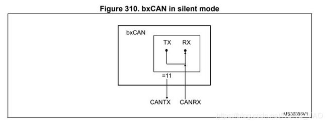
- The bxCAN can be put in Silent mode by setting the SILM bit in the CAN_BTR register.
- In Silent mode, the bxCAN is able to receive valid(有效) data frames(帧) and valid remote frames(有效远程帧), but it sends only recessive(隐性) bits on the CAN bus and it cannot start(启动) a transmission(传输). If the bxCAN has to send a dominant bit(主导位) (ACK bit, overload flag, active error flag), the bit is rerouted(v. 改程;改航) internally(adv. 内部地;国内地;内在地) so that the CAN Core(n. 核心;要点;果心;[计] 磁心vt. 挖...的核) monitors this dominant bit,although the CAN bus may remain in recessive state. Silent mode can be used to analyze the traffic on a CAN bus without affecting it by the transmission of dominant bits (Acknowledge Bits, Error Frames).
过在CAN_BTR寄存器中设置SILM位,bxCAN可以被置于静音模式,静音模式下,bxCAN能够接收有效的数据帧和有效的远程帧,但是它在CAN总线上只能发送隐性位,不能启动传输,如果bxCAN必须发送主导位(ACK位,过载标志,活动错误标志), 这个位是改程内部地,因此CAN核心监视主导位,尽管CAN总线可能保持隐性状态。静音模式可以用于分析can总线上的流量,而不受主导位(确认位、错误帧)的传输的影响。
5.2、Loop back mode 线路循环模式
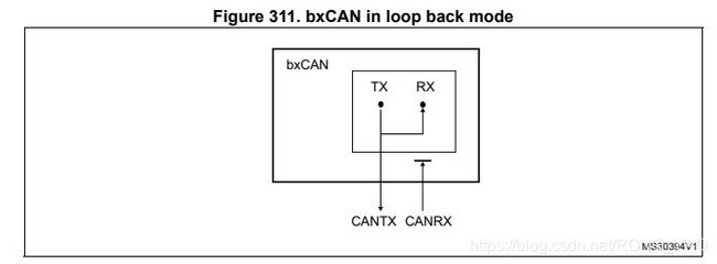
The bxCAN can be set in Loop Back Mode by setting the LBKM bit in the CAN_BTR register. In Loop Back Mode, the bxCAN treats its own transmitted messages as received
messages and stores them (if they pass acceptance filtering) in a Receive mailbox.
通过在CAN_BTR寄存器中设置LBKM位,可以在回循环模式中设置bxCAN。在Loop Back模式中,bxCAN将自己传输的消息视为接收到的消息,并将它们(如果它们通过了接受过滤)存储在接收邮箱中。
- This mode is provided for self-test functions. To be independent of external events, the CAN Core ignores acknowledge errors (no dominant bit sampled in the acknowledge slot of a data / remote frame) in Loop Back Mode. In this mode, the bxCAN performs an internal feedback from its Tx output to its Rx input. The actual value of the CANRX input pin is disregarded by the bxCAN. The transmitted messages can be monitored on the CANTX pin
该模式提供自检功能。要独立于外部事件,就可以在回环模式中,CAN核心忽略确认错误(在数据/远程帧的确认槽中不采样主导位)。在这种模式下,bxCAN从它的Tx输出执行一个内部反馈到它的Rx输入。CANRX输入引脚的实际值被bxCAN忽略。在CANTX引脚上可以监视传输的消息。
5.3、Loop back combined with silent mode 循环回结合沉默模式
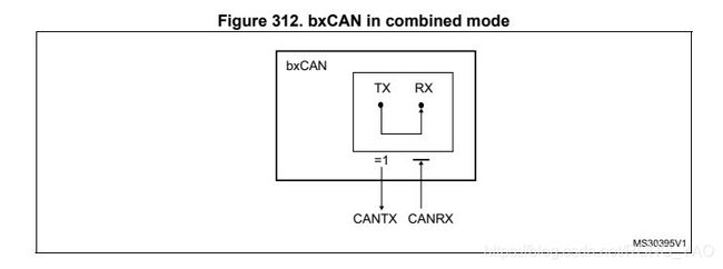
It is also possible(可能的;合理的;合适的) to combine(使化合;使联合,使结合vi. 联合,结合;化合n. 联合收割机;联合企业) Loop Back mode and Silent mode by setting the LBKM and SILM bits in the CAN_BTR register. This mode can be used for a “Hot Selftest”, meaning the bxCAN can be tested like in Loop Back mode but without affecting a running CAN system connected to the CANTX and CANRX pins. In this mode, the CANRX pin is disconnected from the bxCAN and the CANTX pin is held recessive.
在CAN_BTR寄存器通过设置LBKM位和SILM位,它也可能通过合理的结合循环模式和静音模式,这种模式可以用于“热自检”,这意味着bxCAN可以像在回环模式下进行测试,但不影响连接CANTX和CANRX引脚的运行的can系统。在这种模式下,CANRX引脚从bxCAN断开,CANTX引脚是隐性的。
六、Behavior in debug mode 调试模式下的行为
When the microcontroller enters the debug mode (Cortex®-M0 core halted), the bxCAN
continues to work normally or stops, depending on:
当微控制器进入调试模式,(Cortex®-M0核心停止)时,bxCAN继续正常工作或停止,这取决于:
• the DBG_CAN1_STOP bit for CAN1 or the DBG_CAN2_STOP bit for CAN2 in the DBG module.
DBG模块中CAN1的DBG_CAN1_STOP位或CAN2的DBG_CAN2_STOP位
• the DBF bit in CAN_MCR. For more details, refer to Section 29.9.2: CAN control and status registers.
CAN_MCR中的DBF位。更多详细信息,请参阅29.9.2节:CAN控制和状态寄存器。
七、bxCAN functional description bxCAN功能描述
7.1、Transmission handling 传输处理
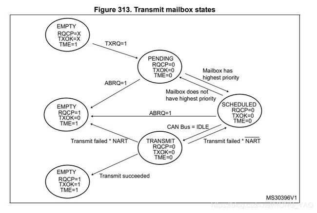
In order to transmit a message, the application must select one empty transmit mailbox, set up the identifier, the data length code (DLC) and the data before requesting the transmission by setting the corresponding TXRQ bit in the CAN_TIxR register. Once the mailbox has left empty state, the software no longer(不在) has write access(进入) to the mailbox registers. Immediately(立即) after the TXRQ bit has been set, the mailbox enters pending (adj. 未决定的;行将发生的 prep. 在……期间;直到……时为止;)state and waits to become the highest priority mailbox, see Transmit Priority. As soon as the mailbox has the highest priority it will be scheduled for transmission. The transmission of the message of the scheduled mailbox will start (enter transmit state) when the CAN bus becomes idle. Once the mailbox has been successfully transmitted, it will become empty again. The hardware indicates a successful transmission by setting the RQCP and TXOK bits in the CAN_TSR register.
为了传递消息,应用程序必须选择一个空的发送邮箱,设置标识符数据长度码(DLC)和请求传输之前的数据在CAN_TIxR寄存器中设置相应的TXRQ位,一旦邮箱处于空状态,该软件不再具有对邮箱寄存器的写访问权限。设置TXRQ位后,邮箱立即进入暂挂状态,等待成为最高优先级的邮箱,参考邮箱优先级,只要邮箱具有最高的优先级,它就会被安排传输。当CAN总线空闲时,调度邮箱的消息传输将启动(进入传输状态)。一旦邮箱被成功传输,它将再次成为空的。硬件通过设置CAN_TSR寄存器中的RQCP和TXOK位来指示成功的传输。
If the transmission fails, the cause is indicated by the ALST bit in the CAN_TSR register in case of an Arbitration(诉讼和仲裁) Lost, and/or the TERR bit, in case of transmission error detection.
For code example refer to the Appendix section A.11.2: bxCAN transmit code example.
如果传输衰减,原因表明在仲裁失败的情况下,由CAN_TSR寄存器中的最后一位指示,以防传输错误检测。
代码示例请参见附录A.11.2节:bxCAN传输代码示例。
/* (1) check mailbox 0 is empty */
/* (2) fill data length = 1 */
/* (3) fill 8-bit data */
/* (4) fill Id field and request a transmission */
if ((CAN->TSR & CAN_TSR_TME0) == CAN_TSR_TME0) /* (1) */
{
 CAN->sTxMailBox[0].TDTR = 1; /* (2) */
 CAN->sTxMailBox[0].TDLR = CMD; /* (3) */
 CAN->sTxMailBox[0].TIR = (uint32_t)(CAN_ID << 21
 | CAN_TI0R_TXRQ); /* (4) */
}
/* check if a message is filtered and received by FIFO 0 */
if ((CAN->RF0R & CAN_RF0R_FMP0)!=0)
{
 CAN_ReceiveMessage = CAN->sFIFOMailBox[0].RDLR; /* read data */
 CAN->RF0R |= CAN_RF0R_RFOM0; /* release FIFO */
 if ((CAN_ReceiveMessage & 0xFF) == CMD)
 {
 /* Process */
 }
}
Transmit priority 传输优先级
by identifier 根据辨识符读数据
When more than one transmit mailbox is pending, the transmission order( 命令;顺序;规则;订单;(生物学)目) is given by the identifier of the message stored(储存;容纳(store 的过去式和过去分词)) in the mailbox. The message with the lowest identifier value has the highest priority according(dj. 相符的;相应的;一致的) to the arbitration of the CAN protocol. If the identifier values are equal, the lower mailbox number will be scheduled first.
当有多个邮箱挂起时,传输顺序由存储在邮箱中的消息的标识符给出,根据CAN协议的仲裁,标识符值最低的消息具有最高的优先级。如果标识符值相等,则先调度较低的邮箱号
By transmit request order 按发送请求命令
The transmit mailboxes can be configured as a transmit FIFO by setting the TXFP bit in the CAN_MCR register. In this mode the priority order is given by the transmit request order.
This mode is very useful for segmented(分段) transmission(传输).
传输邮箱通过CAN_MCR寄存器设置TXFP位配置传输FIFO,在这种模式下优先级顺序由 传输请求顺序给出。
这种方式对于分段传输非常有用
Abort 计划终止
A transmission request can be aborted by the user setting the ABRQ bit in the CAN_TSR register. In pending(挂起,待定) or scheduled(预定) state, the mailbox is aborted immediately( 立即). An abort request while the mailbox is in transmit state can have two results. If the mailbox is transmitted successfully the mailbox becomes empty with the TXOK bit set in the CAN_TSR register. If the transmission fails, the mailbox becomesscheduled, the transmission is aborted and becomes empty with TXOK cleared. In all cases the mailbox will become empty again at least at the end of the current transmission.
一个传输请求可以被用户能通过设置CAN_TSR寄存器的ABRQ位中止,处于挂起或预定状态,邮箱立即中止,邮箱处于传输状态时的中止请求可能有两种结果。如果邮箱传输成功,设置CAN_TSR寄存器的TXOK位邮箱将为空,如果传输失败,传输被中止并变为空,TXOK被清除。在所有情况下,邮箱至少在当前传输结束时将再次变为空。
Non automatic retransmission mode 非自动重传模式
This mode has been implemented(实施) in order to fulfill(实现,满足) the requirement ( 要求;必要条件;必需品)of the Time Triggered Communication option of the CAN standard. To configure the hardware in this mode the NART bit in the CAN_MCR register must be set.
该模式的实现是为了满足时间触发的要求CAN标准的通信选项。在此模式下配置硬件必须设置CAN_MCR寄存器中的NART位。
In this mode, each transmission is started(启动) only once. If the first attempt fails, due to an arbitration loss or an error, the hardware will not automatically restart the message transmission.
这种模式下,每个传输只能启动一次,如果第一次尝试失败 由于仲裁丢失或错误,硬件不会自动重启消息传输。
At the end of the first transmission attempt, the hardware considers the request as completed and sets the RQCP bit in the CAN_TSR register. The result of the transmission is indicated in the CAN_TSR register by the TXOK, ALST and TERR bits.
在第一次传输尝试结束时,硬件认为请求已经完成,并在CAN_TSR寄存器中设置RQCP位。传输的结果在CAN_TSR寄存器中由TXOK、ALST和TERR位指示。
7.2、Time triggered communication mode 时间触发通信模式
In this mode, the internal(内部) counter(计数器) of the CAN hardware is activated and used to generate(生成) the Time Stamp value stored in the CAN_RDTxR/CAN_TDTxR registers, respectively (for Rx
and Tx mailboxes). The internal counter is incremented each CAN bit time (refer to Section 29.7.7: Bit timing). The internal counter is captured on the sample point of the Start Of Frame bit in both reception and transmission.
在这种模式下,CAN硬件的内部计数器被激活并用于生成时间戳值分别存储在CAN_RDTxR/CAN_TDTxR寄存器中(用于Rx和Tx邮箱)。内部计数器每增加一个可以位的时间(参考
第29.7.7节:位定时)。在开始的样本点捕获内部计数器接收和传输中帧位的大小。
7.3、Reception handling 接收处理
For the reception of CAN messages, three mailboxes organized as a FIFO are provided. In order to save CPU load, simplify the software and guarantee data consistency, the FIFO is
managed completely by hardware. The application accesses the messages stored in the FIFO through the FIFO output mailbox.
接收CAN消息,提供了作为FIFO组织的三个邮箱,为了节省CPU负载,简化软件,保证数据一致性,FIFO完全由硬件管理。应用程序访问存储在通过FIFO输出邮箱。
7.3.1、Valid message 有效的消息
A received message is considered as valid when it has been received correctly according to the CAN protocol (no error until the last but one bit of the EOF field) and It passed through
the identifier filtering successfully, see Section 29.7.4: Identifier filtering.
根据CAN协议正确接收到的消息(直到EOF字段的最后一位都没有错误),并且成功通过了标识符过滤(identifier filtering,见29.7.4:identifier filtering),则该消息被认为是有效的。
7.3.2、FIFO management FIFO管理
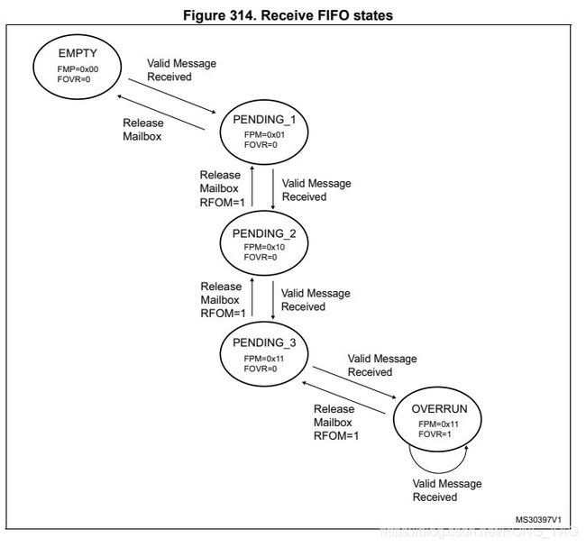
Starting from the empty state, the first valid message received is stored in the FIFO which becomes pending_1. The hardware signals the event setting the FMP[1:0] bits in the
CAN_RFR register to the value 01b. The message is available in the FIFO output mailbox. The software reads out the mailbox content and releases it by setting the RFOM bit in the
CAN_RFR register. The FIFO becomes empty again. If a new valid message has been received in the meantime, the FIFO stays in pending_1 state and the new message is
available in the output mailbox.
从空状态开始,接收到的第一个有效消息存储在FIFO中,它变成pending_1硬件信号事件设置FMP[1:0]位在CAN_RFR寄存器的值为01b。消息在FIFO输出邮箱中可用该软件读取邮箱内容,并通过设置rfrom位释放它CAN_RFR寄存器。FIFO再次变为空。如果在此期间收到了新的有效消息,则FIFO保持在pending_1状态,新消息在输出邮箱中可用。
For code example refer to the Appendix section A.11.3: bxCAN receive code example.
代码示例请参见附录A.11.3节:bxCAN接收代码样列。
/* check if a message is filtered and received by FIFO 0 */
if ((CAN->RF0R & CAN_RF0R_FMP0)!=0)
{
 CAN_ReceiveMessage = CAN->sFIFOMailBox[0].RDLR; /* read data */
 CAN->RF0R |= CAN_RF0R_RFOM0; /* release FIFO */
 if ((CAN_ReceiveMessage & 0xFF) == CMD)
 {
 /* Process */
 }
}
If the application does not release(释放) the mailbox, the next valid message will be stored in the FIFO which enters pending_2 state (FMP[1:0] = 10b). The storage process is repeated for
the next valid message putting the FIFO into pending_3 state (FMP[1:0] = 11b). At this point, the software must release the output mailbox by setting the RFOM bit, so that a mailbox is free to store the next valid message. Otherwise the next valid message received will cause a loss of message.
如果应用程序没有释放邮箱,下一个有效消息将存储在FIFO进入pending_2状态(FMP[1:0] = 10b)。对下一个有效消息重复存储过程,将FIFO置于pending_3状态(FMP[1:0] = 11b)。此时,软件必须通过设置rfrom位释放输出邮箱,以便邮箱可以自由存储下一个有效消息。否则,接收到的下一个有效消息将导致消息丢失。
Refer also to Section 29.7.5: Message storage
请参见第29.7.5节:消息存储
7.3.3、Overrun 超出限度
Once the FIFO is in pending_3 state (i.e. the three mailboxes are full) the next valid message reception will lead to an overrun and a message will be lost. The hardware signals the overrun condition by setting the FOVR bit in the CAN_RFR register. Which message is lost depends on the configuration of the FIFO:
- If the FIFO lock function is disabled (RFLM bit in the CAN_MCR register cleared) the last message stored in the FIFO will be overwritten by the new incoming message. In this case the latest messages will be always available to the application.
- If the FIFO lock function is enabled (RFLM bit in the CAN_MCR register set) the most recent message will be discarded and the software will have the three oldest messages in the FIFO available.
一旦FIFO处于pending_3状态(即三个邮箱已满),下一个有效的消息接收将导致溢出并丢失一条消息。硬件通过在CAN_RFR寄存器中设置FOVR位来指示超限情况。哪条消息丢失取决于FIFO的配置:
- 如果关闭了FIFO锁功能(清除了CAN_MCR寄存器中的RFLM位),存储在FIFO中的最后一条消息将被新的传入消息覆盖。在这种情况下,应用程序将始终使用最新消息。
- 如果FIFO锁功能启用(在CAN_MCR寄存器设置的RFLM位),最新的消息将被丢弃,软件将有三个最早的消息在FIFO可用。
7.3.4、Reception related interrupts 接收相关的中断
- Once a message has been stored in the FIFO, the FMP[1:0] bits are updated and an interrupt request is generated if the FMPIE bit in the CAN_IER register is set.
- When the FIFO becomes full (i.e. a third message is stored) the FULL bit in the CAN_RFR register is set and an interrupt is generated if the FFIE bit in the CAN_IER register is set.
- On overrun condition, the FOVR bit is set and an interrupt is generated if the FOVIE bit in the CAN_IER register is set.
- 一旦一条消息被存储在FIFO中,FMP[1:0]位被更新,如果CAN_IER寄存器中的FMPIE位被设置,一个中断请求被生成。
- 当FIFO被填满(即第三条消息被存储)时,CAN_RFR寄存器中的完整位被设置,如果CAN_IER寄存器中的FFIE位被设置,则会生成一个中断
- 在超限条件下,如果设置CAN_IER寄存器中的FOVIE位,则设置FOVR位并生成中断。
7.4、Identifier filtering 标识符过滤
In the CAN protocol the identifier of a message is not associated( 关联的;联合的) with the address of a node but related(有关系的,有关联的;讲述的,叙述的) to the content of the message. Consequently a transmitter broadcasts its message to all receivers. On message reception a receiver node decides - depending on the identifier value - whether the software needs the message or not. If the message is needed, it is copied into the SRAM. If not, the message must be discarded without intervention by the software.
在CAN协议中,消息的标识符与节点的地址无关,而是与消息的内容相关因此,发射器会把它的信息广播给所有的接收器。在接收消息时,接收节点根据标识符值决定软件是否需要该消息。如果需要消息,它就被复制到SRAM中。如果不是,则必须丢弃该消息,而不需要软件干预。
To fulfill this requirement the bxCAN Controller provides 14 configurable and scalable filter banks (13-0) to the application, in order to receive only the messages the software needs.
为了满足这一要求,bxCAN控制器为应用程序提供了14个可配置和可扩展的过滤器组(13-0),以便只接收软件需要的消息。
This hardware filtering saves CPU resources which would be otherwise needed to perform filtering by software. Each filter bank x consists of two 32-bit registers, CAN_FxR0 and CAN_FxR1.
这种硬件过滤节省了软件执行过滤时需要的CPU资源。每个filter bank x由两个32位寄存器组成,CAN_FxR0和CAN_FxR1。
7.4.1、Scalable width 可伸缩的宽度
To optimize and adapt the filters to the application needs, each filter bank can be scaled independently. Depending on the filter scale a filter bank provides:
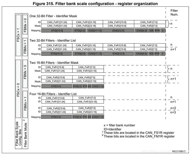
• One 32-bit filter for the STDID[10:0], EXTID[17:0], IDE and RTR bits.
• Two 16-bit filters for the STDID[10:0], RTR, IDE and EXTID[17:15] bits.
Refer to Figure 315.
Furthermore, the filters can be configured in mask mode or in identifier list mode.
为了优化和调整过滤器以适应应用的需要,每个过滤器组都可以独立扩展。根据不同的过滤器规模,过滤器组提供:
一个32位的STDID[10:0], EXTID[17:0], IDE和RTR位过滤器
两个16位过滤器的STDID[10:0], RTR, IDE和EXTID[17:15]位。
此外,可以在掩码模式或标识符列表模式下配置过滤器。
7.4.2、Mask mode 蒙版模式
In mask mode the identifier registers are associated with mask registers specifying which bits of the identifier are handled as “must match” or as “don’t care”.
在掩码模式下,标识符寄存器与掩码寄存器相关联,指定标识符的哪些位被处理为“必须匹配”或“不关心”。
7.4.3、Identifier list mode 标识符列表模式
In identifier list mode, the mask registers are used as identifier registers. Thus instead of(不是) defining an identifier and a mask, two identifiers are specified(adj. 规定的;详细说明的v. 指定;详细说明(specify的过去分词)), doubling the number of single identifiers. All bits of the incoming identifier must match the bits specified in the filter registers.
在标识符列表模式下,掩码寄存器被用作标识符寄存器。因此,不是定义一个标识符和一个掩码,而是指定两个标识符,使单个标识符的数量加倍。传入标识符的所有位必须与筛选器寄存器中指定的位相匹配。
7.4.4、Filter bank scale and mode configuration滤波器组规模和模式配置
The filter banks are configured by means of(……的方式……的手段) the corresponding(adj. 相当的,相应的;一致的;通信的) CAN_FMR register. To configure a filter bank it must be deactivated by clearing the FACT bit in the CAN_FAR register. The filter scale is configured by means of the corresponding FSCx bit in the CAN_FS1R register, refer to Figure 315. The identifier list or identifier mask mode for the corresponding Mask/Identifier registers is configured by means of the FBMx bits in the CAN_FMR register.
通过相应的CAN_FMR寄存器来配置滤波器组,要配置筛选器组,必须通过清除CAN_FAR寄存器中的事实位来禁用它,通过对应FSCx位来配置滤波尺度CAN_FS1R寄存器,参见图315。对应的掩码/标识寄存器的标识符列表或标识符掩码模式是通过FBMx位来配置的CAN_FMR寄存器
To filter a group of identifiers, configure the Mask/Identifier registers in mask mode.
如果要过滤一组标识符,需要以掩码方式配置掩码/标识符寄存器。
To select single identifiers, configure the Mask/Identifier registers in identifier list mode.
通过选择单一标识符,在标识符列表清单下配置掩码/标识符寄存器
Filters not used by the application should be left deactivated.
应用程序未使用的过滤器应该保持禁用状态。
Each filter within a filter bank is numbered (called the Filter Number) from 0 to a maximum dependent on the mode and the scale of each of the filter banks.Concerning the filter configuration, refer to Figure 315.
根据每个滤波器组的模式和规模,对滤波器组中的每个滤波器进行从0到最大值的编号(称为滤波器号)。
Concerning the filter configuration, refer to Figure 315.
关于过滤器的配置请参见图315。
7.4.5、Filter match index 过滤匹配指数
Once a message has been received in the FIFO it is available to the application. Typically, application data is copied into SRAM locations. To copy the data to the right location the
application has to identify the data by means of the identifier. To avoid this, and to ease the access to the SRAM locations, the CAN controller provides a Filter Match Index.
在FIFO中接收到消息后,应用程序就可以使用该消息,通常,应用程序数据被复制到SRAM的位置。要将数据复制到正确的位置,应用程序必须通过标识符来识别数据。为了避免这种情况,并且为了方便对SRAM位置的访问,CAN控制器提供了一个过滤器匹配索引。
This index is stored in the mailbox together with the message according to the filter priority rules. Thus each received message has its associated filter match index.
根据筛选器优先级规则,该索引与邮件一起存储在邮箱中。因此,每个接收到的消息都有其关联的过滤器匹配索引。
The Filter Match index can be used in two ways:
• Compare(比较) the Filter Match index with a list of expected values.
• Use the Filter Match Index as an index on an array to access the data destination location.
过滤器匹配索引有两种用法:
- 将过滤器匹配索引与期望值列表进行比较。
- 使用筛选器匹配索引作为数组上的索引来访问数据目标位置.
For non masked filters, the software no longer has to compare the identifier.
对于非屏蔽过滤器,软件不再需要比较标识符。
If the filter is masked the software reduces the comparison to the masked bits only.
如果过滤器被屏蔽,软件只减少与屏蔽位的比较
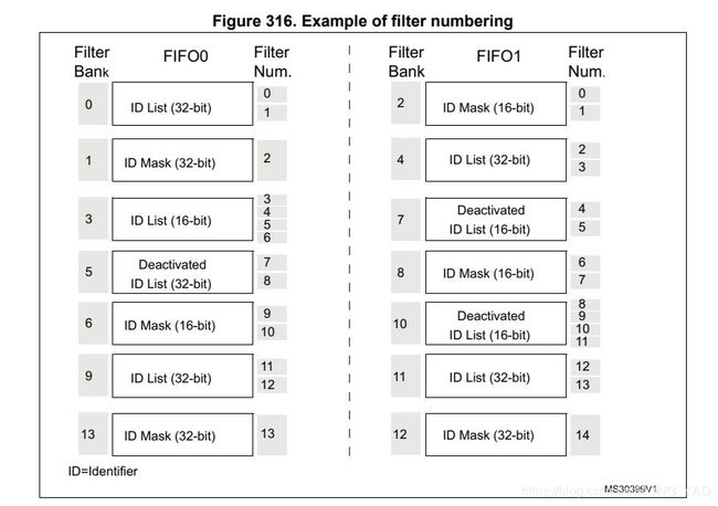
The index value of the filter number does not take into account the activation state of the filter banks. In addition, two independent numbering schemes are used, one for each FIFO.
Refer to Figure 316 for an example.
过滤数的指标值不考虑过滤组的激活状态。此外,使用了两个独立的编号方案,每个FIFO一个。请参考图316
7.4.6、过滤器优先级规则 Filter priority rules
- Depending on the filter combination it may occur that an identifier passes successfully through several filters. In this case the filter match value stored in the receive mailbox is chosen according to the following priority rules:
根据筛选器组合的不同,可能会出现一个标识符成功通过多个筛选器的情况。在这种情况下,存储在接收邮箱中的过滤器匹配值将根据以下优先级规则进行选择
- A 32-bit filter takes priority over a 16-bit filter.
32位过滤器优先级高于16位过滤器
- For filters of equal scale, priority is given to the Identifier List mode over the Identifier Mask mode
对于同等规模的过滤器,标识符列表模式优先于标识符模式蒙版模式
- For filters of equal scale and mode, priority is given by the filter number (the lower the number, the higher the priority).
对于相同规模和模式的过滤器,优先级由过滤器号决定(过滤器号越小,优先级越高)。
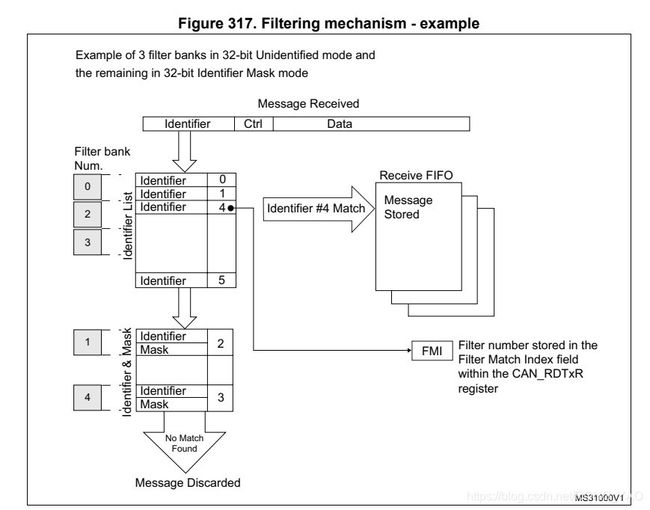
- The example above shows the filtering principle of the bxCAN. On reception of a message, the identifier is compared first with the filters configured in identifier list mode. If there is a match, the message is stored in the associated FIFO and the index of the matching filter is stored in the Filter Match Index. As shown in the example, the identifier matches with Identifier #2 thus the message content and FMI 2 is stored in the FIFO.
上面的例子展示了bxCAN的过滤原理。在接收到消息时,标识符首先与标识符列表模式下配置的过滤器进行比较。如果有匹配,消息将存储在相关的FIFO中,匹配过滤器的索引将存储在过滤器匹配索引中。如示例所示,标识符匹配因此消息内容和FMI 2存储在FIFO中
- If there is no match, the incoming identifier is then compared with the filters configured in mask mode.
如果没有匹配,则将输入的标识符与掩码模式下配置的过滤器进行比较
- If the identifier does not match any of the identifiers configured in the filters, the message is discarded by hardware without disturbing the software.
如果标识符与过滤器中配置的任何标识符不匹配,则该消息将被硬件丢弃,而不会影响软件
7.5、Message storage 消息存储
The interface between the software and the hardware for the CAN messages is implemented by means of mailboxes. A mailbox contains all information related to a message; identifier, data, control, status and time stamp information.
CAN消息的软件和硬件之间的接口是通过邮箱实现的。邮箱包含所有与邮件相关的信息;标识符、数据、控件、状态和时间戳信息
7.5.1、Transmit mailbox 邮箱传输
The software sets up the message to be transmitted in an empty transmit mailbox. The status of the transmission is indicated by hardware in the CAN_TSR register.
软件在一个空的传输邮箱里设置传输消息,CAN_TSR寄存器,传输的状态由CAN_TSR寄存器中的硬件指示。
7.5.2、Receive mailbox 接收邮箱
When a message has been received, it is available(adj. 可获得的;可购得的;可找到的;有空的) to the software in the FIFO output mailbox. Once the software has handled the message (e.g. read it) the software must release the FIFO output mailbox by means of the RFOM bit in the CAN_RFR register to make the next incoming message available. The filter match index is stored in the MFMI
field of the CAN_RDTxR register. The 16-bit time stamp value is stored in the TIME[15:0] field of CAN_RDTxR.
收到消息的时候,它是可用的软件在FIFO输出邮箱。一旦软件处理了消息(例如读它),软件必须通过在CAN_RFR寄存器中的rfrom位释放FIFO输出邮箱,以使下一个传入消息可用。过滤器匹配索引存储在CAN_RDTxR寄存器的MFMI字段中。16位的时间戳值存储在CAN_RDTxR的time[15:0]字段中。
7.6、Error management 错误管理
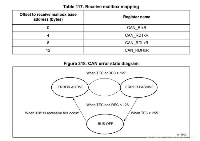
The error management as described in the CAN protocol is handled entirely by hardware using a Transmit Error Counter (TEC value, in CAN_ESR register) and a Receive Error
Counter (REC value, in the CAN_ESR register), which get incremented or decremented according to the error condition. For detailed information about TEC and REC management,
please refer to the CAN standard.
CAN协议中描述的错误管理完全由硬件使用发送错误计数器(TEC值,在CAN_ESR寄存器中)和接收错误处理计数器(CAN_ESR寄存器中的REC值),根据错误条件递增或递减。关于TEC和REC管理的详细信息,请参考CAN标准。
Both of them may be read by software to determine the stability of the network. Furthermore, the CAN hardware provides detailed information on the current error status in CAN_ESR register. By means of the CAN_IER register (ERRIE bit, etc.), the software can configure the interrupt generation on error detection in a very flexible way.
它们都可以通过软件读取来确定网络的稳定性。此外,CAN硬件提供当前错误状态的详细信息CAN_ESR寄存器。通过CAN_IER寄存器(ERRIE位等),软件可以非常灵活地配置错误检测上的中断生成。
7.6.1、Bus-Off recovery 总线关闭复苏
The Bus-Off state is reached when TEC is greater than 255, this state is indicated by BOFF bit in CAN_ESR register. In Bus-Off state, the bxCAN is no longer able to transmit and receive messages.
当TEC大于255时达到总线断开状态,这种状态由CAN_ESR寄存器中的BOFF位指示。在总线断开状态下,bxCAN不再能够发送和接收消息。
Depending on the ABOM bit in the CAN_MCR register bxCAN will recover from Bus-Off (become error active again) either automatically or on software request. But in both cases the bxCAN has to wait at least for the recovery sequence specified in the CAN standard (128 occurrences of 11 consecutive recessive bits monitored on CANRX).If ABOM is set, the bxCAN will start the recovering sequence automatically after it has entered Bus-Off state.
根据CAN_MCR寄存器中的ABOM位,bxCAN将从总线断开中恢复(再次激活错误)自动或根据软件请求。但在这两种情况下,bxCAN至少必须等待CAN标准中指定的恢复顺序(CANRX上监视的11个连续隐性位出现128次)。
If ABOM is set, the bxCAN will start the recovering sequence automatically after it has entered Bus-Off state.
如果设置了ABOM,则bxCAN在进入总线断开状态后会自动启动恢复序列
If ABOM is cleared, the software must initiate the recovering sequence by requesting bxCAN to enter and to leave initialization mode.
如果ABOM被清除,软件必须通过请求bxCAN进入和离开初始化模式来启动恢复序列。
Note: In initialization mode, bxCAN does not monitor the CANRX signal, therefore it cannot complete the recovery sequence. To recover, bxCAN must be in normal mode.
在初始化模式下,bxCAN不监视CANRX信号,因此无法完成恢复序列。要恢复,bxCAN必须处于正常模式。
7.7、Bit timing 位定时
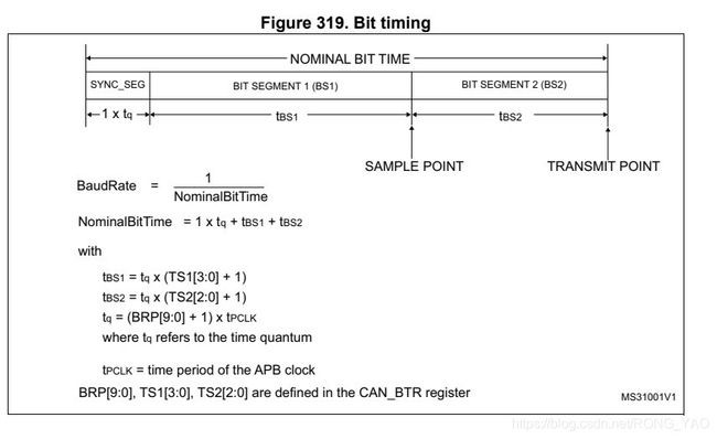
The bit timing logic monitors the serial bus-line and performs sampling and adjustment of the sample point by synchronizing on the start-bit edge and resynchronizing on the following edges.
位时序逻辑监视串行总线,并通过在起始位边缘上同步并在随后的边缘上重新同步来执行采样点的采样和调整。
Its operation may be explained simply by splitting nominal bit time into three segments as follows:
它的作用可以简单地用将标称位时间分成如下三段来解释:
Synchronization segment (SYNC_SEG): a bit change is expected to occur within this time segment. It has a fixed length of one time quantum (1 x tq)
同步段(SYNC_SEG):预计在这个时间段内会发生一点变化。它有一个固定长度的时间量子(1 x tq)。
• Bit segment 1 (BS1): defines the location of the sample point. It includes the PROP_SEG and PHASE_SEG1 of the CAN standard. Its duration is programmable between 1 and 16 time quanta but may be automatically lengthened to compensate for positive phase drifts due to differences in the frequency of the various nodes of the network.
第1位段(BS1):定义采样点的位置。它包含了CAN标准的PROP_SEG和PHASE_SEG1。它的持续时间可编程在1到16个时间量子量之间,但可以自动延长以补偿由于网络中各个节点的频率不同而产生的正相位漂移。
• Bit segment 2 (BS2): defines the location of the transmit point. It represents the PHASE_SEG2 of the CAN standard. Its duration is programmable between 1 and 8 time quanta but may also be automatically shortened to compensate for negative phase drifts.
第2位段 (BS2):定义传输点的位置。它代表了CAN标准的PHASE_SEG2。它的持续时间是可编程的1到8时间量子,但也可以自动缩短,以补偿负相位漂移。
The resynchronization Jump Width (SJW) defines an upper bound to the amount of lengthening or shortening of the bit segments. It is programmable between 1 and 4 time quanta.
再同步跳宽(SJW)定义了比特段延长或缩短的上限。它在1到4倍量子之间可编程。
- A valid(有效) edge(上升沿) is defined as the first transition in a bit time from dominant(显性的;占优势的) to recessive bus level(水平;标准;水平面) provided the controller itself does not send a recessive bit.
一个有效的上升沿被定义为在一个比特时间内从显性总线级别到隐性总线级别的第一个过渡,前提是控制器本身不发送一个隐性比特。
- If a valid edge is detected in BS1 instead of SYNC_SEG, BS1 is extended by up to SJW so that the sample point is delayed.
如果在BS1中检测到一条有效的上升沿而不是SYNC_SEG,则将BS1扩展到SJW,使采样点延迟。
- Conversely, if a valid edge is detected in BS2 instead of SYNC_SEG, BS2 is shortened by up to SJW so that the transmit point is moved earlier.
相反,如果在BS2中检测到有效的上升沿而不是SYNC_SEG,则BS2最多缩短SJW,以便发射点提前移动。
- As a safeguard against programming errors, the configuration of the Bit Timing Register (CAN_BTR) is only possible while the device is in Standby mode.
作为防止编程错误的一种保护措施,位定时寄存器(CAN_BTR)的配置只有在设备处于待机模式时才可能
- Note: For a detailed description of the CAN bit timing and resynchronization mechanism, please refer to the ISO 11898 standard.
注意:有关CAN位定时和再同步机制的详细描述,请参阅ISO 11898标准
八、bxCAN interrupts
Four interrupt vectors( 向量) are dedicated (专用的)to bxCAN. Each interrupt source can be independently enabled or disabled by means of the CAN Interrupt Enable Register (CAN_IER).
有四个中断向量专用于bxCAN。每个中断源可以通过can interrupt Enable寄存器(CAN_IER)独立地启用或禁用。
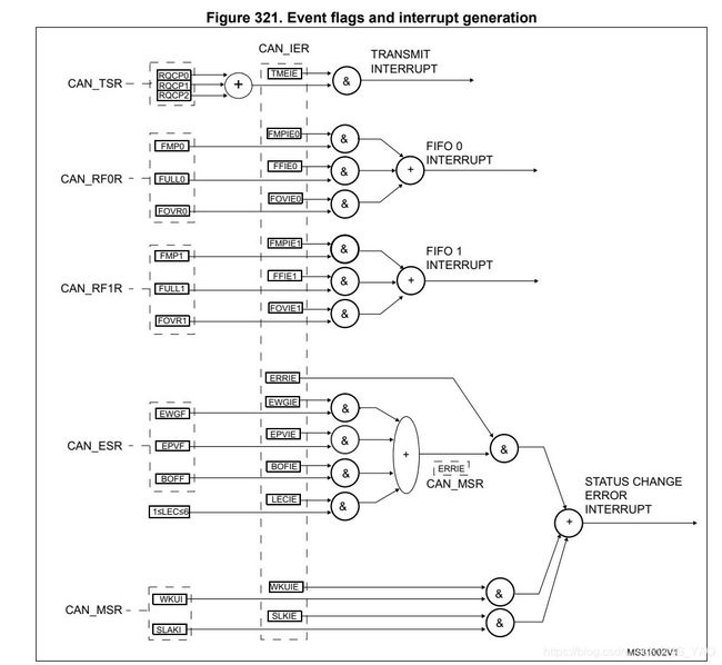
The transmit interrupt can be generated by the following events:
传输中断能生成下面的事件
– Transmit mailbox 0 becomes empty, RQCP0 bit in the CAN_TSR register set.
传输邮箱从0变成空,设置CAN_TSR寄存器的RQCP0位
– Transmit mailbox 1 becomes empty, RQCP1 bit in the CAN_TSR register set.
– Transmit mailbox 2 becomes empty, RQCP2 bit in the CAN_TSR register set.
• The FIFO 0 interrupt can be generated by the following events:
FIFO 0中断能生成下面的事件
– Reception of a new message, FMP0 bits in the CAN_RF0R register are not ‘00’.
接收新的消息,设置寄存器的FMP0位不为0
– FIFO0 full condition, FULL0 bit in the CAN_RF0R register set.
– FIFO0 overrun condition(超出运行的条件), FOVR0 bit in the CAN_RF0R register set.
The FIFO 1 interrupt can be generated by the following events:
– Reception of a new message, FMP1 bits in the CAN_RF1R register are not ‘00’.
– FIFO1 full condition, FULL1 bit in the CAN_RF1R register set.
– FIFO1 overrun condition, FOVR1 bit in the CAN_RF1R register set.
• The error and status change interrupt can be generated by the following events:
– Error condition, for more details( 细节(detail的复数);详细资料) on error conditions please refer to the CAN Error Status register (CAN_ESR).
– Wakeup condition, SOF monitored on the CAN Rx signal.
– Entry into Sleep mode.
九、CAN 寄存器 CAN registers
The peripheral registers have to be accessed by words (32 bits).
外围寄存器必须通过字(32位)来访问。
9.1、Register access protection 寄存器访问保护
Erroneous access to certain configuration registers can cause the hardware to temporarily disturb the whole CAN network. Therefore the CAN_BTR register can be modified by software only while the CAN hardware is in initialization mode.
Although the transmission of incorrect data will not cause problems at the CAN network level, it can severely disturb the application. A transmit mailbox can be only modified by software while it is in empty state, refer to Figure 313: Transmit mailbox states.
The filter values can be modified either deactivating the associated filter banks or by setting the FINIT bit. Moreover, the modification of the filter configuration (scale, mode and FIFO assignment) in CAN_FMxR, CAN_FSxR and CAN_FFAR registers can only be done when the filter initialization mode is set (FINIT=1) in the CAN_FMR register.
9.2、CAN control and status registers CAN控制和状态寄存器
Refer to Section 1.1 for a list of abbreviations(缩写词,缩略语;[语] 缩写) used in register descriptions.
9.2.1、CAN master control register (CAN_MCR) CAN主控制寄存器
Address offset(地址偏移): 0x00
Reset value(复位值): 0x0001 0002
Bits 31:17 Reserved, must be kept at reset value. 保留值,必须保持复位值
Bit 16 DBF: Debug freeze 调试冻结
0: CAN working during debug 调试期间CAN正常工作
1: CAN reception/transmission frozen(冻结) during debug. Reception FIFOs can still be accessed/controlled normally. 冻结CAN的接收/发送。仍然可以正常地(读写)访问和控制接收FIFO
Bit 15 RESET: bxCAN software master reset bxCAN软件主复位
0: Normal operation. 标准操作
1: Force(强制) a master reset of the bxCAN -> Sleep mode activated after reset (FMP bits and CAN_MCR register are initialized to the reset values). This bit is automatically reset to 0.
强制bxCAN主复位->睡眠模式激活后复位(FMP位和CAN_MCR寄存器初始化为复位值)这个位会自动重置为0。
Bits 14:8 Reserved, must be kept at reset value. 保留值 ,必须保持为复位值
Bit 7 TTCM: Time triggered communication mode 时间触发通信模式
0: Time Triggered Communication mode disabled. 失能时间触发通信模式
1: Time Triggered Communication mode enabled 使能时间触发通信模式
Note: For more information on Time Triggered Communication mode, please refer to Section 29.7.2: Time triggered communication mode.
注意:有关时间触发通信模式更多的消息,请参考章节 29.7.2,时间触发通信模式。
Bit 6 ABOM: Automatic bus-off management 自动总线关闭管理
This bit controls the behavior of the CAN hardware on leaving( 离开;留下;) the Bus-Off state. 这一位控制CAN硬件在离开总线关闭状态的行为。
0: The Bus-Off state is left on (留住)software request, once 128 occurrences(出现,生成) of 11 recessive(隐性位) bits have been monitored and the software has first set and cleared the INRQ bit of the CAN_MCR register. 总线关闭状态在软件请求时被保留,一旦监测到11个隐性位的128次出现,并且软件已经首先设置并清除CAN_MCR寄存器的INRQ位
软件请求留下总线关闭状态 一旦出现128次11位的隐性位 清除CAN_MCR寄存器的INRQ位
1: The Bus-Off state is left automatically by hardware once 128 occurrences of 11 recessive bits have been monitored.一旦11位隐性位出现128次,硬件就会自动离开总线状态。
For detailed information on the Bus-Off state please refer to Section 29.7.6: Error management. 关于总线断开状态的详细信息请参见29.7.6:错误管理。
Bit 5 AWUM: Automatic wakeup mode自动唤醒模式
This bit controls the behavior of the CAN hardware on message reception during Sleep mode. 该位控制在休眠模式下CAN硬件接收消息时的行为。
0: The Sleep mode is left on software request by clearing the SLEEP bit of the CAN_MCR register.
睡眠模式下软件请求清除CAN_MCR寄存器的SLEEP位
1: The Sleep mode is left automatically by hardware on CAN message detection.
The SLEEP bit of the CAN_MCR register and the SLAK bit of the CAN_MSR register are cleared by hardware.
Bit 4 NART: No automatic retransmission 没有自动重传
0: The CAN hardware will automatically retransmit the message until it has been successfully transmitted according to the CAN standard.
CAN硬件会根据CAN标准自动重新发送信息,直到信息成功传输。
1: A message will be transmitted only once, independently of the transmission result (successful, error or arbitration lost).
一条消息只会传输一次,与传输结果无关(成功、错误或仲裁失败)
Bit 3 RFLM: Receive FIFO locked mode 接收FIFO锁定模式
0: Receive FIFO (先进先出)not locked on overrun. Once a receive FIFO is full the next incoming message will overwrite the previous one.
接收未锁定(FIFO)在溢出。一旦一个接收的FIFO被填满,下一个传入的消息将覆盖前一个。
1: Receive FIFO locked against overrun. Once a receive FIFO is full the next incoming message will be discarded.(丢弃)
接收FIFO锁定防止超时。一旦一个接收的FIFO被填满,下一个传入的消息将被丢弃。
Bit 2 TXFP: Transmit FIFO priority 当多个邮箱同时挂起时,此位控制传输顺序。
This bit controls the transmission order when several mailboxes are pending at the same time. 此位控制传输序列,
0: Priority driven by the identifier of the message
1: Priority driven by the request order (chronologically)
Bit 1 SLEEP: Sleep mode request 睡眠模式请求
This bit is set by software to request the CAN hardware to enter the Sleep mode. Sleep
mode will be entered as soon as the current CAN activity (transmission or reception of a CAN frame) has been completed.
This bit is cleared by software to exit Sleep mode.
This bit is cleared by hardware when the AWUM bit is set and a SOF bit is detected on the CAN Rx signal.
This bit is set after reset - CAN starts in Sleep mode.
Bit 0 INRQ: Initialization request 初始化请求
The software clears this bit to switch the hardware into normal mode. Once 11 consecutive recessive bits have been monitored on the Rx signal (信号)the CAN hardware is synchronized and ready for transmission and reception. Hardware signals this event by clearing the INAK bit in the CAN_MSR register.
软件清除这个位以将硬件切换到正常模式,11个连续的隐性位,已经在Rx信号上监测了CAN硬件同步,并准备好发送和接收。硬件通过清除CAN_MSR寄存器中的INAK位来通知这个事件。
Software sets this bit to request the CAN hardware to enter initialization mode. Once software has set the INRQ bit, the CAN hardware waits until the current (现在的;流通的,通用的;最近的;草写的)CAN activity (transmission or reception) is completed(完成;填写(表格);(使)完整;完成房地产的销售;(四分卫)成功地向前传球;(使)完美(complete 的过去式及过去分词)adj. 完成的;初次同房的;完整的) before entering the initialization mode. Hardware signals this event by setting the INAK bit in the CAN_MSR register.
软件设置此位请求CAN硬件进入初始化模式,一旦软件设置INRQ位,CAN硬件等待当前的CAN活动(发送或接收)完成后才进入初始化模式,硬件通过在CAN_MSR寄存器中设置INAK位来通知这个事件。
9.2.2、CAN master status register (CAN_MSR) CAN主状态寄存器
(偏移量)Address offset: 0x04
(复位值)Reset value: 0x0000 0C02
Bits 31:12 Reserved, must be kept at reset value. 保留,必须保持复位值
Bit 11 RX: CAN Rx signal CAN接收信号
Monitors the actual value of the CAN_RX Pin. 监视CAN_RX引脚的实际值。
Bit 10 SAMP: Last sample point 最后一个采样点
The value of RX on the last sample point (current received bit value).(当前接收位值)接收最后一个采样点的值
Bit 9 RXM: Receive mode 接收模式
The CAN hardware is currently receiver. CAN硬件当前是接收器
Bit 8 TXM: Transmit mode 传输模式
The CAN hardware is currently transmitter. CAN硬件目前是发射器
Bits 7:5 Reserved, must be kept at reset value.
Bit 4 SLAKI: Sleep acknowledge interrupt Sleep承认中断
When SLKIE=1, this bit is set by hardware to signal that the bxCAN has entered Sleep Mode. When set, this bit generates a status change interrupt if the SLKIE bit in the CAN_IER register is set.
This bit is cleared by software or by hardware, when SLAK is cleared.当SLKIE=1时,这个位被硬件设置为bxCAN进入睡眠状态的信号模式。当设置时,如果SLKIE位在设置CAN_IER寄存器。
Note: When SLKIE=0, no polling on SLAKI is possible. In this case (情况)the SLAK bit can be polled(查询).注意:当SLKIE=0时,不可能对SLAKI进行查询。在这种情况下,可以查询SLAK位。
Bit 3 WKUI: Wakeup interrupt 唤醒中断
This bit is set by hardware to signal that a SOF bit has been detected while the CAN hardware was in Sleep mode. Setting this bit generates a status change interrupt if the WKUIE bit in the CAN_IER register is set. 当CAN硬件处于睡眠模式时,这个位由硬件设置来表示检测到一个SOF位,此位设置一个状态改变中断,如果 CAN_IER寄存器设置WKUIE位
This bit is cleared by software. 此为被软件清除
Bit 2 ERRI: Error interrupt 错误中断
This bit is set by hardware when a bit of the CAN_ESR has been set on error detection(检测) and the corresponding(相当,相应) interrupt in the CAN_IER is enabled. Setting this bit generates(产生) a status change interrupt if the ERRIE bit in the CAN_IER register is set.当在错误检测上设置了CAN_ESR的一位,并且CAN_IER中相应的中断被启用时,该位由硬件设置。如果设置了CAN_IER寄存器中的ERRIE位,则设置此位会产生一个状态改变中断。
This bit is cleared by software. 软件清除这个位
Bit 1 SLAK: Sleep acknowledge Sleep承认
This bit is set by hardware and indicates(指示) to the software that the CAN hardware is now in Sleep mode. This bit acknowledges the Sleep mode request from the software (set SLEEP bit in CAN_MCR register).
This bit is cleared by hardware when the CAN hardware has left Sleep mode (to be synchronized on the CAN bus). To be synchronized the hardware has to monitor a sequence of 11 consecutive recessive bits on the CAN RX signal. CAN硬件离开Sleep模式的时候这个位被从硬件上清除,要同步,硬件监视CAN Rx信号的连续11个隐性位
Note: The process of leaving Sleep mode is triggered when the SLEEP bit in the CAN_MCR register is cleared. Please refer to the AWUM bit of the CAN_MCR register description for detailed information for clearing SLEEP bit.当清除CAN_MCR寄存器中的Sleep位时,将触发离开Sleep模式的过程。关于清除休眠位的详细信息,请参考CAN_MCR寄存器描述的AWUM位
Bit 0 INAK: Initialization acknowledge 初始化承认
This bit is set by hardware and indicates(指示) to the software that the CAN hardware is now in initialization mode. This bit acknowledges(承认) the initialization request from the software (set INRQ bit in CAN_MCR register).这个位是由硬件设置的,并指示软件CAN硬件现在处于初始化模式。此位承认来自软件(set . exe)的初始化请求(CAN_MCR寄存器中的INRQ位)。
This bit is cleared by hardware when the CAN hardware has left (离开)the initialization mode (to be synchronized on the CAN bus). To be synchronized the hardware has to monitor a sequence(n. [数][计] 序列;顺序;续发事件) of 11 consecutive(dj. 隐性的;逆行的;后退的) recessive bits on the CAN RX signal. CAN硬件离开初始化模式时这个位从硬件上清除(在CAN总线上被同步),要同步,硬件必须监控CAN RX信号上11个连续的隐性位的序列。
9.2.3、CAN transmit status register(CAN_TSR)
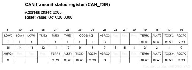
Bit 31 LOW2: Lowest priority flag for mailbox 2 邮箱2的最低优先级标志
This bit is set by hardware when more than one mailbox are pending for transmission and mailbox 2 has the lowest priority.当有多个邮箱等待传输且邮箱2的优先级最低时,由硬件设置此位。
Bit 30 LOW1: Lowest priority flag for mailbox 1 邮箱1的最低优先级标志
This bit is set by hardware when more than one mailbox are pending for transmission and mailbox 1 has the lowest priority.当有多个邮箱等待传输且邮箱1的优先级最低时,由硬件设置此位。
Bit 29 LOW0: Lowest priority flag for mailbox 0 邮箱0的最低优先级标志
This bit is set by hardware when more than one mailbox are pending for transmission and mailbox 0 has the lowest priority.
Note: The LOW[2:0] bits are set to zero when only one mailbox is pending 当只有一个邮箱挂起时,低[2:0]位被设置为零。.
Bit 28 TME2: Transmit mailbox 2 empty (空)
This bit is set by hardware when no transmit request is pending for mailbox 2. 邮箱2没有挂起传输请求时,此位由硬件设置。
Bit 27 TME1: Transmit mailbox 1 empty
This bit is set by hardware when no transmit request is pending for mailbox 1.
Bit 26 TME0: Transmit mailbox 0 empty
This bit is set by hardware when no transmit request is pending for mailbox 0.
Bits 25:24 CODE[1:0]: Mailbox code 邮箱编码
In case at least ( 最小的;最少的)one transmit mailbox is free, the code value is equal (平等的;相等的;胜任的vt. 等于;比得上)to the number of the next transmit mailbox free(空闲).如果至少有一个传输邮箱是空闲的,该代码值等于下一个空闲传输邮箱的数目。
In case all transmit mailboxes are pending, the code value is equal to the number of the transmit mailbox with the lowest priority.所有的邮箱挂起时,则代码值等于具有最低优先级的传输邮箱的编号
Bit 23 ABRQ2: Abort request for mailbox 2 中止对邮箱2的请求
Set by software to abort the transmission request for the corresponding(相应的,对应的) mailbox. 软件设置传输请求相应的邮箱终止
Cleared by hardware when the mailbox becomes empty. 当邮箱变为空的时,由硬件清除
Setting this bit has no effect when the mailbox is not pending for transmission. 当邮箱没有等待传输时,设置此位将不起作用。
Bits 22:20 Reserved, must be kept at reset value.
Bit 19 TERR2: Transmission error of mailbox 2 邮箱2传输错误
This bit is set when the previous TX failed due to an error. 在Tx之前失败导致错误时,设置这个位
Bit 18 ALST2: Arbitration(仲裁) lost for mailbox 2 邮箱2仲裁失败
This bit is set when the previous(在...之前) TX failed due to an arbitration lost. 在传输(Tx)失败前导致仲裁失败时,设置此位
Bit 17 TXOK2: Transmission OK of mailbox 2 邮箱2传输ok
The hardware updates this bit after each transmission attempt. 每次传输尝试后,硬件都会更新这个位
0: The previous transmission failed 传输是被之前
1: The previous transmission was successful 传输成功之前
This bit is set by hardware when the transmission request on mailbox 2 has been completed successfully. Please refer to Figure 313. 当邮箱2传输请求成功完成时,由硬件设置此位
Bit 16 RQCP2: Request completed mailbox2 邮箱2请求完成
Set by hardware when the last request (transmit or abort) has been performed(执行,表演). 最后的请求执行时,由硬件设置此位
Cleared by software writing a “1” or by hardware on transmission request (TXRQ2 set in CAN_TMID2R register).通过软件写一个“1”或通过硬件在传输请求(TXRQ2设置)来清除
Clearing this bit clears all the status bits (TXOK2, ALST2 and TERR2) for Mailbox 2.清除此位清除邮箱2的所有状态位(TXOK2, ALST2和TERR2)。
Bit 15 ABRQ1: Abort request for mailbox 1 中止对邮箱1的请求
Set by software to abort the transmission request for the corresponding mailbox. 由软件设置,以中止对相应邮箱的传输请求。
Cleared by hardware when the mailbox becomes empty. 当邮箱变为空时,由硬件清除
Setting this bit has no effect when the mailbox is not pending for transmission.当邮箱没有等待传输时,设置此位将不起作用
Bits 14:12 Reserved, must be kept at reset value.
Bit 11 TERR1: Transmission error of mailbox1 邮箱 1传输错误
This bit is set when the previous TX failed due to an error. 当前一个TX由于错误而失败时设置此位
Bit 10 ALST1: Arbitration lost for mailbox1 1号邮箱仲裁失败
This bit is set when the previous TX failed due to an arbitration lost. 当由于仲裁失败而导致前一个TX失败时设置此位。
Bit 9 TXOK1: Transmission OK of mailbox1邮箱1的传输OK
The hardware updates this bit after each transmission attempt.,每一次传输尝试后硬件更新
0: The previous transmission failed 上次传输失败
1: The previous transmission was successful 之前的传输是成功的
This bit is set by hardware when the transmission request on mailbox 1 has been completed successfully. Please refer to Figure 313当邮箱1上的传输请求成功完成时,由硬件设置此位。请参考图313
Bit 8 RQCP1: Request completed mailbox1 邮箱1请求完成
Set by hardware when the last request (transmit or abort) has been performed.当最后一个请求(传输或中止)已经执行时,由硬件设置
Cleared by software writing a “1” or by hardware on transmission request (TXRQ1 set in CAN_TI1R register).通过软件写一个“1”或在传输请求(TXRQ1设置)时由硬件来清除CAN_TI1R寄存器)。
Clearing this bit clears all the status bits (TXOK1, ALST1 and TERR1) for Mailbox 1.清除此位清除邮箱1的所有状态位(TXOK1, ALST1和TERR1)。
Bit 7 ABRQ0: Abort request for mailbox0 中止对mailbox0的请求
Set by software to abort the transmission request for the corresponding mailbox. 由软件设置,以中止对相应邮箱的传输请求。
Cleared by hardware when the mailbox becomes empty.
Setting this bit has no effect when the mailbox is not pending for transmission.当邮箱没有等待传输时,设置此位将不起作用
Bits 6:4 Reserved, must be kept at reset value.
Bit 3 TERR0: Transmission error of mailbox0
This bit is set when the previous TX failed due to an error. 当前一个TX由于错误而失败时设置此位。
Bit 2 ALST0: Arbitration lost for mailbox0 邮箱0仲裁失败
This bit is set when the previous TX failed due to an arbitration(n. 公断,仲裁) lost. 当由于仲裁失败而导致前一个TX失败时设置此位。
Bit 1 TXOK0: Transmission OK of mailbox0
The hardware updates this bit after each transmission attempt. 每次传输尝试后,硬件都会更新这个位
0: The previous transmission failed 之前传输失败
1: The previous transmission was successful 之前的传输是成功的
This bit is set by hardware when the transmission request on mailbox 1 has been completed successfully. Please refer to Figure 313 当邮箱1上的传输请求成功完成时,由硬件设置此位。请参考图313
Bit 0 RQCP0: Request completed mailbox0 请求已完成mailbox0
Set by hardware when the last request (transmit or abort) has been performed( 执行,表演). 当最后一个请求(传输或中止)已经执行时,由硬件设置
Cleared by software writing a “1” or by hardware on transmission request (TXRQ0 set in CAN_TI0R register).通过软件写一个“1”或通过硬件在传输请求(TXRQ0设置)时清除
CAN_TI0R寄存器)。
Clearing this bit clears all the status bits (TXOK0, ALST0 and TERR0) for Mailbox 0.清除此位清除邮箱0的所有状态位(TXOK0, ALST0和TERR0)。
9.2.4、CAN receive FIFO 0 register(CAN_RF0R)
Bits 31:6 Reserved, must be kept at reset value.
Bit 5 RFOM0: Release FIFO 0 output mailbox 释放FIFO 0输出邮箱
Set by software to release the output mailbox of the FIFO. The output mailbox can only be released when at least one message is pending in the FIFO. Setting this bit when the FIFO
is empty has no effect. If at least two messages are pending in the FIFO, the software has to release the output mailbox to access the next message.
通过软件设置释放FIFO的输出邮箱。只有在FIFO中至少有 一条消息挂起时,才能释放输出邮箱。当FIFO为空时设置此位不起作用。如果至少有两条消息在FIFO中挂起,则软件必须释放输出邮箱以访问下一条 消息
Cleared by hardware when the output mailbox has been released.当输出邮箱被释放时,由硬件清除。
Bit 4 FOVR0: FIFO 0 overrun
This bit is set by hardware when a new message has been received and passed the filter 当接收到新消息并通过筛选器时,该位由硬件设置
while the FIFO was full.而FIFO已经满了
This bit is cleared by software. 。此位由软件清除。
Bit 3 FULL0: FIFO 0 full
Set by hardware when three messages are stored in the FIFO. 当三条消息存储在FIFO中时,由硬件设置。
This bit is cleared by software. 此位由软件清除。
Bit 2 Reserved, must be kept at reset value.
Bits 1:0 FMP0[1:0]: FIFO 0 message pending
These bits indicate how many messages are pending in the receive FIFO. 这些位表示在接收FIFO中有多少消息正在等待处理。
FMP is increased each time the hardware stores a new message in to the FIFO. FMP is decreased each time the software releases the output mailbox by setting the RFOM0 bit
每当硬件在FIFO中存储一条新消息时,FMP就会增加。当软件通过设置RFOM0位释放输出邮箱时,FMP就会减少
9.2.5、CAN receive FIFO 1 register(CAN_RF1R)
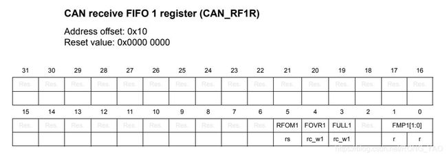
Bits 31:6 Reserved, must be kept at reset value.
Bit 5 RFOM1: Release FIFO 1 output mailbox 释放FIFO 1输出邮箱
Set by software to release the output mailbox of the FIFO. The output mailbox can only be released when at least one message is pending in the FIFO. Setting this bit when the FIFO
is empty has no effect. If at least two messages are pending in the FIFO, the software has to release the output mailbox to access the next message.
通过软件设置释放FIFO的输出邮箱。只有在FIFO中至少有一条消息挂起时,才能释放输出邮箱。当FIFO为空时设置此位不起作用。如果至少有两条消息在FIFO中挂起,则软件必须释放输出邮箱以访问下一条消息。
Cleared by hardware when the output mailbox has been released.当输出邮箱被释放时,由硬件清除。
Bit 4 FOVR1: FIFO 1 overrun FIFO 1 溢出
This bit is set by hardware when a new message has been received and passed the filter while the FIFO was full. This bit is cleared by software.当接收到一条新消息并在FIFO满的时候通过过滤器时,由硬 件设置此位。此位由软件清除。
Bit 3 FULL1: FIFO 1 full
Set by hardware when three messages are stored in the FIFO.当三条消息存储在FIFO中时,由硬件设置
This bit is cleared by software. 此位由软件清除。
Bit 2 Reserved, must be kept at reset value.
Bits 1:0 FMP1[1:0]: FIFO 1 message pending FIFO 1消息暂挂
These bits indicate how many messages are pending in the receive FIFO1. 这些位表示在接收FIFO1中有多少消息正在等待处理。
FMP1 is increased each time the hardware stores a new message in to the FIFO1. FMP is decreased each time the software releases the output mailbox by setting the RFOM1 bit.
当硬件在FIFO1中存储一条新消息时,FMP1就会增加。当软件通过设置RFOM1位释放输出邮箱时,FMP就会减少。
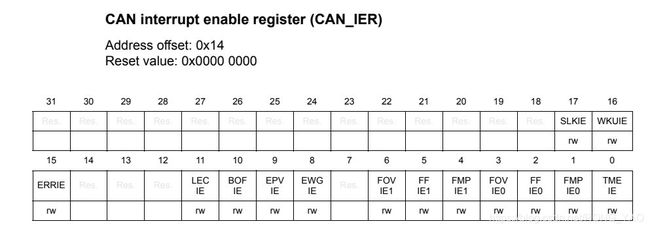
9.2.6、CAN interrupt enable register(CAN_IER)
Bits 31:18 Reserved, must be kept at reset value.
Bit 17 SLKIE: Sleep interrupt enable 睡眠中断使能
0: No interrupt when SLAKI bit is set. 设置SLAKI位时没有中断
1: Interrupt generated when SLAKI bit is set. 设置SLAKI位时中断生成
Bit 16 WKUIE: Wakeup interrupt enable 唤醒中断使能
0: No interrupt when WKUI is set.
1: Interrupt generated when WKUI bit is set.
Bit 15 ERRIE: Error interrupt enable 错误中断使能
0: No interrupt will be generated when an error condition is pending in the CAN_ESR. 当错误条件在CAN_ESR中挂起时,不会生成中断
1: An interrupt will be generation when an error condition is pending in the CAN_ESR.当错误条件在CAN_ESR中挂起时,生成中断
Bits 14:12 Reserved, must be kept at reset value.
Bit 11 LECIE: Last error code interrupt enable 最后错误编码中断使能
0: ERRI bit will not be set when the error code in LEC[2:0] is set by hardware on error detection.当LEC[2:0]中的错误码被硬件错误检测设置时,ERRI位不会被设置。
1: ERRI bit will be set when the error code in LEC[2:0] is set by hardware on error detection.当硬件在错误检测上设置LEC[2:0]中的错误码时,ERRI位将被设置
Bit 10 BOFIE: Bus-off interrupt enable Bus-off中断使能
0: ERRI bit will not be set when BOFF is set. 设置BOFF时ERRI将不会设置
1: ERRI bit will be set when BOFF is set. 设置BOFF时ERRI将会设置
Bit 9 EPVIE: Error passive(被动的) interrupt enable 错误被动的中断使能
0: ERRI bit will not be set when EPVF is set.
1: ERRI bit will be set when EPVF is set.
Bit 8 EWGIE: Error warning interrupt enable 错误警告中断使能
0: ERRI bit will not be set when EWGF is set.
1: ERRI bit will be set when EWGF is set.
Bit 7 Reserved, must be kept at reset value.
Bit 6 FOVIE1: FIFO overrun interrupt enable FIFO溢出中断使能
0: No interrupt when FOVR is set.
1: Interrupt generation when FOVR is set.
Bit 5 FFIE1: FIFO full interrupt enable FIFO完整中断使能
0: No interrupt when FULL bit is set.
1: Interrupt generated when FULL bit is set.
Bit 4 FMPIE1: FIFO message pending interrupt enable
0: No interrupt generated when state of FMP[1:0] bits are not 00b.
1: Interrupt generated when state of FMP[1:0] bits are not 00b.
Bit 3 FOVIE0: FIFO overrun interrupt enable
0: No interrupt when FOVR bit is set.
1: Interrupt generated when FOVR bit is set.
Bit 2 FFIE0: FIFO full interrupt enable
0: No interrupt when FULL bit is set.
1: Interrupt generated when FULL bit is set. 设置FULL位时,生成中断
Bit 1 FMPIE0: FIFO message pending interrupt enable FIFO消息挂起中断使能
0: No interrupt generated when state(规定,声明) of FMP[1:0] bits are not 00b. 声明FMP[1:0]位不是00b时不生成中断
1: Interrupt generated when state of FMP[1:0] bits are not 00b.
Bit 0 TMEIE: Transmit mailbox empty interrupt enable 传输邮箱空中断使能
0: No interrupt when RQCPx bit is set. 设置RQCP位时没有中断
1: Interrupt generated when RQCPx bit is set. 设置RQCPx位时中断生成
Note: Refer to Section 29.8: bxCAN interrupts. 注意:参考章节29.8:bxCAN中断
9.2.7、CAN error status register(CAN_ESR)
Bits 31:24 REC[7:0]: Receive error counter 接收错误计数器
The implementing part of the fault confinement mechanism of the CAN protocol. In case of an error during reception, this counter is incremented by 1 or by 8 depending on the error
condition as defined by the CAN standard. After every successful reception the counter is decremented by 1 or reset to 120 if its value was higher than 128. When the counter value
exceeds 127, the CAN controller enters the error passive state.
CAN协议的故障约束机制的实现部分。如果在接收过程中出现错误,该计数器将根据CAN标准定义的错误条件增加1或8。在每次成功接收之后,计数器将减少1,如果计数器的值大于128,计数器将重置为120。当计数器的值超过127时,CAN控制器进入错误被动状态
Bits 23:16 TEC[7:0]: Least significant byte of the 9-bit transmit error counter The implementing part of the fault confinement mechanism of the CAN protocol.9位传输错误计数器的最低有效字节
CAN协议的故障约束机制的实现部分。
Bits 15:7 Reserved, must be kept at reset value.
Bits 6:4 LEC[2:0]: Last error code 最后一次出错情况
This field(字段) is set by hardware and holds(持有) a code which indicates(指示) the error condition of the last error detected (检测)on the CAN bus. If a message has been transferred (reception or transmission) without error, this field will be cleared to ‘0’. 这个字段是由硬件设置的,并持有一个代码,该代码指示在CAN总线上检测到的最后一个错误的错误条件。如果消息传送(接收或传输)没有错误,此字段将被清除为' 0
The LEC[2:0] bits can be set to value 0b111 by software. They are updated by hardware to indicate the current communication status.EC[2:0]位可以通过软件设置为值0b111。它们由硬件更新,以指示当前的通信状态。
000: No Error
001: Stuff Error
010: Form Error
011: Acknowledgment Error
100: Bit recessive Error
101: Bit dominant Error
110: CRC Error
111: Set by software
Bit 3 Reserved, must be kept at reset value.
Bit 2 BOFF: Bus-off flag
This bit is set by hardware when it enters the bus-off state. The bus-off state is entered on TEC overflow, greater than 255, refer to Section 29.7.6 on page 829.当进入总线断开状态时,该位由硬件设置。总线断开状态进入onTEC溢出,大于255,请参阅第829页的29.7.6节。
Bit 1 EPVF: Error passive flag
This bit is set by hardware when the Error Passive limit has been reached (Receive Error Counter or Transmit Error Counter>127).当达到错误被动限制(接收错误)时,由硬件设置此位计数器或传输错误计数器>127)。
Bit 0 EWGF: Error warning flag
This bit is set by hardware when the warning limit has been reached (Receive Error Counter or Transmit Error Counter≥96).当达到警告限制时,该位由硬件设置(接收错误计数器或发送错误计数器≥96)。
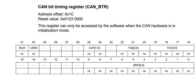
9.2.8、CAN bit timing(定时) register(CAN_BTR)
Bit 31 SILM: Silent mode (debug) 静默模式(调试)
0: Normal operation 正常运行
1: Silent(adj. (silent) 沉默的;寂静的;无记载的n. (silent) 无声电影) Mode
Bit 30 LBKM: Loop back mode (debug)
0: Loop Back Mode disabled Loop Back模式禁用
1: Loop Back Mode enabled
Bits 29:26 Reserved, must be kept at reset value.
Bits 25:24 SJW[1:0]: Resynchronization jump width 同步跳转宽度
These bits define the maximum number of time quanta the CAN hardware is allowed to lengthen or shorten a bit to perform the resynchronization.这些位定义了CAN硬件允许延长或缩短一个位来执行重同步的最大时间量程数。
tRJW = tq x (SJW[1:0] + 1)
Bit 23 Reserved, must be kept at reset value.
Bits 22:20 TS2[2:0]: Time segment 2
These bits define the number of time quanta in Time Segment 2. 这些位定义了时间段2中时间量子量的数量
tBS2 = tq x (TS2[2:0] + 1)
Bits 19:16 TS1[3:0]: Time segment 1 时间部分1
These bits define the number of time quanta(量子;定额,定量;) in Time Segment( 段,部分) 1 这些位定义了时间段1中时间量子量的数量
tBS1 = tq x (TS1[3:0] + 1)
For more information on bit timing, please refer to Section 29.7.7: Bit timing on page 829.有关位定时的更多信息
Bits 15:10 Reserved, must be kept at reset value.
Bits 9:0 BRP[9:0]: Baud rate prescaler 波特率预分频
These bits define the length of a time quanta. 这些位元定义了一个时间量子的长度
tq = (BRP[9:0]+1) x tPCLK
9.3、CAN mailbox registers
9.3.1、 CAN TX mailbox identifier register (CAN_TIxR) (x = 0..2) CAN TX邮箱标识符寄存器(CAN_TIxR) (x = 0..2)
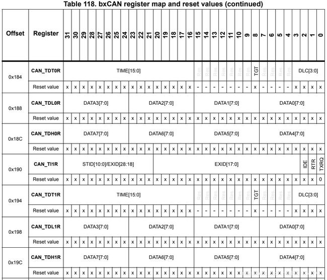
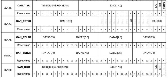
Address offsets: 0x180, 0x190, 0x1A0
Reset value: 0xXXXX XXXX (except bit 0, TXRQ = 0)
All TX registers are write protected when the mailbox is pending transmission (TMEx reset). 当邮箱等待传输(TMEx重置)时,所有TX寄存器都是写保护的。
This register also implements the TX request control (bit 0) - reset value 0.这个寄存器也实现了TX请求控制(0位)-重置值0。
Bits 31:21 STID[10:0]/EXID[28:18]: Standard identifier or extended identifier
The standard identifier or the MSBs of the extended identifier (depending on the IDE bit
value).
Bit 20:3 EXID[17:0]: Extended identifier
The LSBs of the extended identifier.
Bit 2 IDE: Identifier extension
This bit defines the identifier type of message in the mailbox.
0: Standard identifier.
1: Extended identifier.
Bit 1 RTR: Remote transmission request
0: Data frame
1: Remote frame
Bit 0 TXRQ: Transmit mailbox request
Set by software to request the transmission for the corresponding mailbox.
Cleared by hardware when the mailbox becomes empty
9.3.2、CAN mailbox data length control and time stamp register(CAN_TDTxR) (x = 0..2)邮箱数据长度可以控制和时间戳寄存器
(CAN_TDTxR) (x = 0..2)
Bits 31:16 TIME[15:0]: Message time stamp
This field contains the 16-bit timer value captured at the SOF transmission.
Bits 15:9 Reserved, must be kept at reset value.
Bit 8 TGT: Transmit global time
This bit is active only when the hardware is in the Time Trigger Communication mode,
TTCM bit of the CAN_MCR register is set.
0: Time stamp TIME[15:0] is not sent.
1: Time stamp TIME[15:0] value is sent in the last two data bytes of the 8-byte message:
TIME[7:0] in data byte 7 and TIME[15:8] in data byte 6, replacing the data written in CAN_TDHxR[31:16] register (DATA6[7:0] and DATA7[7:0]). DLC must be programmed as 8 in order these two bytes to be sent over the CAN bus.
Bits 7:4 Reserved, must be kept at reset value.
Bits 3:0 DLC[3:0]: Data length code
This field defines the number of data bytes a data frame contains or a remote frame request.
A message can contain from 0 to 8 data bytes, depending on the value in the DLC field.
9.3.3、CAN mailbox data low register (CAN_TDLxR) (x = 0..2) CAN邮箱数据低寄存器
All bits of this register are write protected when the mailbox is not in empty state.当邮箱不处于空状态时,该寄存器的所有位都是写保护的。
Bits 31:24 DATA3[7:0]: Data byte 3
Data byte 3 of the message.
Bits 23:16 DATA2[7:0]: Data byte 2
Data byte 2 of the message.
Bits 15:8 DATA1[7:0]: Data byte 1 数据字节1的消息。
Data byte 1 of the message.
Bits 7:0 DATA0[7:0]: Data byte 0
Data byte 0 of the message. 消息的数据字节0。
A message can contain from 0 to 8 data bytes and starts with byte 0 一条消息可以包含0到8个数据字节,并从字节0开始
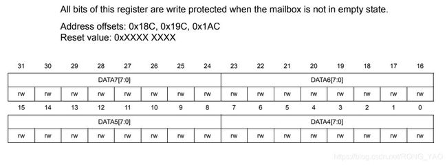
9.3.4、CAN mailbox data high register (CAN_TDHxR) (x = 0..2)
Bits 31:24 DATA7[7:0]: Data byte 7
Data byte 7 of the message.
Note: If TGT of this message and TTCM are active, DATA7 and DATA6 will be replaced by the TIME stamp value.如果此消息的TGT和TTCM处于活动状态,则DATA7和DATA6将被时间戳值取代。
Bits 23:16 DATA6[7:0]: Data byte 6
Data byte 6 of the message.
Bits 15:8 DATA5[7:0]: Data byte 5
Data byte 5 of the message.
Bits 7:0 DATA4[7:0]: Data byte 4
Data byte 4 of the message 消息的数据字节4
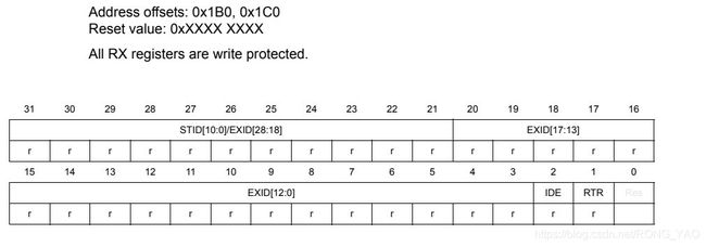
9.3.5、CAN receive FIFO mailbox identifier register (CAN_RIxR) (x = 0..1)能接收FIFO寄存器的邮箱标识符
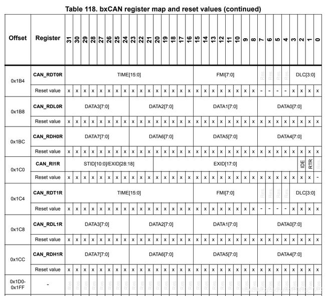
Bits 31:21 STID[10:0]/EXID[28:18]: Standard identifier or extended identifier
The standard identifier or the MSBs of the extended identifier (depending on the IDE bit value).扩展标识符的标准标识符或MSBs(取决于IDE位值)。
Bits 20:3 EXID[17:0]: Extended identifier 扩展标识符
The LSBs of the extended identifier. 扩展标识符的LSBs
Bit 2 IDE: Identifier extension 标识别符扩展
This bit defines the identifier type of message in the mailbox.此位定义邮箱中消息的标识符类型。
0: Standard identifier. 0:标准标识符。
1: Extended identifier. 1:扩展标识符
Bit 1 RTR: Remote transmission request远程传输请求
0: Data frame
1: Remote frame 远程帧
Bit 0 Reserved, must be kept at reset value.
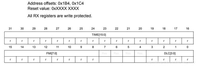
9.3.6、CAN receive FIFO mailbox data length control and time stamp register (CAN_RDTxR) (x = 0..1)
Bits 31:16 TIME[15:0]: Message time stamp 消息时间戳
This field contains the 16-bit timer value captured at the SOF detection.此字段包含在SOF检测时捕获的16位定时器值。
Bits 15:8 FMI[7:0]: Filter match index
This register contains the index of the filter the message stored in the mailbox passed through. For more details on identifier filtering please refer to Section 29.7.4: Identifier
filtering on page 823 - Filter Match Index paragraph. 此寄存器包含存储在传递的邮箱中的消息的过滤器的索引。有关标识符过滤的详细信息,请参阅第29.7.4节:标识符过滤在823页-过滤匹配索引段。
Bits 7:4 Reserved, must be kept at reset value.
Bits 3:0 DLC[3:0]: Data length code 数据长度码
T his field defines the number of da ta bytes a data frame contains (0 to 8). It is 0 in the case of a remote frame request.这个字段定义了一个数据帧包含的数据字节数(0到8)。在远程帧请求的情况下是0。
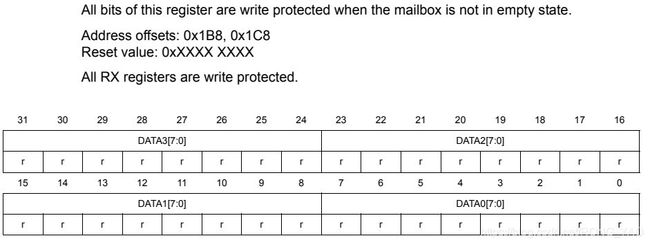
9.3.7、CAN receive FIFO mailbox data low register (CAN_RDLxR) (x = 0..1)
Bits 31:24 DATA3[7:0]: Data Byte 3
Data byte 3 of the message.
Bits 23:16 DATA2[7:0]: Data Byte 2
Data byte 2 of the message.
Bits 15:8 DATA1[7:0]: Data Byte 1
Data byte 1 of the message.
Bits 7:0 DATA0[7:0]: Data Byte 0
Data byte 0 of the message.
A message can contain from 0 to 8 data bytes and starts with byte 0. 一个消息包含0到8的数据字节位,并从字节0开始。
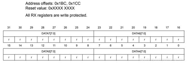
9.3.8、CAN receive FIFO mailbox data high register (CAN_RDHxR) (x = 0..1)
Bits 31:24 DATA7[7:0]: Data Byte 7
Data byte 3 of the message.
Bits 23:16 DATA6[7:0]: Data Byte 6
Data byte 2 of the message.
Bits 15:8 DATA5[7:0]: Data Byte 5
Data byte 1 of the message.
Bits 7:0 DATA4[7:0]: Data Byte 4
Data byte 0 of the message.
9.4、CAN filter( 过滤器;滤波器) registers
9.4.1、CAN filter master register (CAN_FMR)
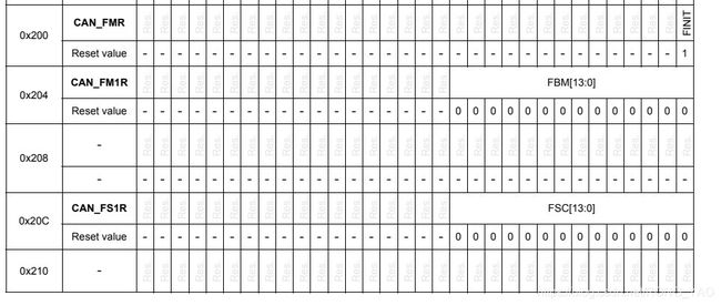
Bits 31:1 Reserved, must be kept at reset value.
Bit 0 FINIT: Filter initialization mode 过滤初始化模式
Initialization mode for filter banks 滤波器组的初始化模式
0: Active filters mode. 活跃的过滤模式
1: Initialization mode for the filters. :过滤器的初始化模式。
9.4.2、CAN filter mode register (CAN_FM1R)
Address offset: 0x204
Reset value: 0x0000 0000
This register can be written only when the filter initialization mode is set (FINIT=1) in the CAN_FMR register.寄存器只能在过滤器初始化模式被设置(FINIT=1)时写入CAN_FMR寄存器
Bits 31:14 Reserved, must be kept at reset value.
Bits 13:0 FBMx: Filter mode
Mode of the registers of Filter x. 滤波器x的寄存器模式。
0: Two 32-bit registers of filter bank x are in Identifier Mask mode. 过滤器组 x的两个32位寄存器处于标识符掩码模式。
1: Two 32-bit registers of filter bank x are in Identifier List mode. 过滤器组 x的两个32位寄存器处于标识符列表模式。
9.4.3、CAN filter scale register (CAN_FS1R)
Address offset: 0x20C
Reset value: 0x0000 0000
This register can be written only when the filter initialization mode is set (FINIT=1) in the CAN_FMR register寄存器只能在过滤器初始化模式被设置(FINIT=1)时写入CAN_FMR寄存器
Bits 31:14 Reserved, must be kept at reset value.
Bits 13:0 FSCx: Filter scale configuration 过滤器配置规模
These bits define the scale configuration of Filters 13-0. 这些位定义了过滤器13-0的规模配置。
0: Dual 16-bit scale configuration 双16位缩放配置
1: Single 32-bit scale configuration 单32位缩放配置
Note: Please refer to Figure 315: Filter bank scale configuration - register organization on page 825. 请参见图315:过滤器组规模配置-注册组织在第825页。
9.4.4、CAN filter FIFO assignment register (CAN_FFA1R)
Address offset: 0x214
Reset value: 0x0000 0000
This register can be written only when the filter initialization mode is set (FINIT=1) in the CAN_FMR register寄存器只能在过滤器初始化模式被设置(FINIT=1)时写入CAN_FMR寄存器
Bits 31:14 Reserved, must be kept at reset value.
Bits 13:0 FFAx: Filter FIFO assignment for filter x 过滤器 FIFO赋值给过滤器 x
The message passing through this filter will be stored in the specified FIFO.通过这个过滤器的消息将存储在指定的FIFO中。
0: Filter assigned to FIFO 0 过滤器分配给FIFO 0
1: Filter assigned to FIFO 1
9.4.5、CAN filter activation register (CAN_FA1R)
Bits 31:14 Reserved, must be kept at reset value.
Bits 13:0 FACTx: Filter active
The software sets this bit to activate Filter x. To modify the Filter x registers (CAN_FxR[0:7]), the FACTx bit must be cleared or the FINIT bit of the CAN_FMR register must be set.软件设置这个位来激活Filter x。要修改Filter x寄存器(CAN_FxR[0:7]),必须清除FACTx位或者设置CAN_FMR寄存器的FINIT位。
0: Filter x is not active
1: Filter x is active
9.4.6、Filter bank i register x (CAN_FiRx) (i = 0..13, x = 1, 2)
Address offsets: 0x240 to 0x2AC
Reset value: 0xXXXX XXXX
There are 14 filter banks, i= 0 to 13. Each filter bank i is composed of two 32-bit registers, CAN_FiR[2:1].有14个过滤器组,i= 0 ~ 13。每个滤波器组i由两个32位寄存器组成,CAN_FiR[2:1]
This register can only be modified when the FACTx bit of the CAN_FAxR register is cleared or when the FINIT bit of the CAN_FMR register is set.有当清除了CAN_FAxR寄存器的FACTx位或者设置了CAN_FMR寄存器的FINIT位时,才能修改这个寄存器。
In all configurations:在所有的配置
Bits 31:0 FB[31:0]: Filter bits
Identifier
Each bit of the register specifies the level of the corresponding bit of the expected identifier. 寄存器的每个位都指定了期望标识符的对应位的级别
0: Dominant bit is expected 预计占主导位
1: Recessive bit is expected 隐性比特是预期的
Mask
Each bit of the register specifies whether the bit of the associated identifier register must match with the corresponding bit of the expected identifier or not.寄存器的每个位指定关联标识符寄存器的位是否必须与期望标识符的对应位匹配。
0: Do not care, the bit is not used for the comparison 不管,这个位不是用来比较的
1: Must match, the bit of the incoming identifier must have the same level has specified in the corresponding identifier register of the filter.必须匹配,入站标识符的位必须与过滤器的相应标识符寄存器中指定的级别相同吗
Note: Depending on the scale and mode configuration of the filter the function of each register can differ. For the filter mapping, functions description and mask registers association, refer to Section 29.7.4: Identifier filtering on page 823.根据过滤器的规模和模式配置,每个寄存器的功能可以不同。关于过滤器映射,函数描述和掩码寄存器的关联,请参阅第29.7.4节:823页的标识符过滤。
A Mask/Identifier register in mask mode has the same bit mapping as in identifier list mode. 掩码模式下的掩码/标识符寄存器与标识符列表模式下的位映射相同。
For the register mapping/addresses of the filter banks please refer to the Table 118 on page 854.有关滤波器组的寄存器映射/地址,请参阅第854页的表118。
9.5、bxCAN register map
