在前文Arduino+ESP32 之 驱动GC9A01圆形LCD(一),
我们已经移植好了arduino GFX库, 该库的示例程序内,还有LVGL的示例程序哦。
arduino环境下移植lvgl是很方便的,我们一起来移植一个,并且跑一下lvgl的示例demo!
由于arduino的library这个路径内的arduino工程文件是只读的,不便于我们编译测试示例程序,所以我们复制一份lvgl的示例程序到桌面上的我的一个文件夹内。
打开LvglHelloWorld.ino工程文件。
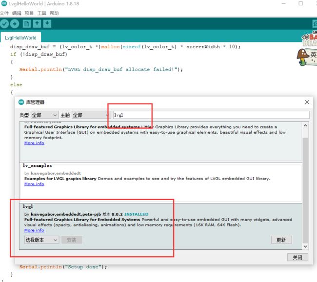
工具->管理库->库管理器,搜索LVGL并在线安装。我安装的是8.0.2版本,建议你也安装V8版本的LVGL,因为arduino GFX库的LVGL的示例程序是基于V8版本的。
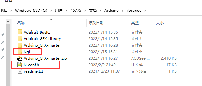
安装好LVGL以后,library路径下会出现lvgl文件夹。复制lvgl文件夹内的lv_conf_template.h,我们将其重命名为lv_conf.h,放在library路径下。
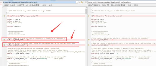
为了让lvgl适配我的硬件LCD,我修改了几个参数。大部分的SPI 或者IIC的LCD,需要修改的地方都是这几处。
我修改的地方(红色箭头所指):
1. 跑arduino GFX库的LVGL的示例程序,LvglHelloWorld
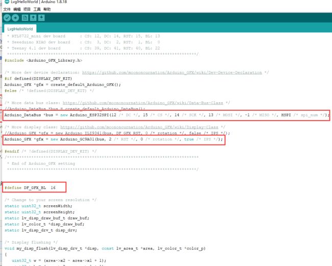
修改LvglHelloWorld.ino工程文件的三处代码:
代码源文件:
#include

/*******************************************************************************
 * LVGL Hello World
 * This is a simple examplle for LVGL - Light and Versatile Graphics Library
 *
 * Dependent libraries:
 * LVGL: https://github.com/lvgl/lvgl.git
 ******************************************************************************/


/*******************************************************************************
 * Start of Arduino_GFX setting
 *
 * Arduino_GFX try to find the settings depends on selected board in Arduino IDE
 * Or you can define the display dev kit not in the board list
 * Defalult pin list for non display dev kit:
 * Arduino Nano, Micro and more: CS:  9, DC:  8, RST:  7, BL:  6
 * ESP32 various dev board     : CS:  5, DC: 27, RST: 33, BL: 22
 * ESP32-C3 various dev board  : CS:  7, DC:  2, RST:  1, BL:  3
 * ESP32-S2 various dev board  : CS: 34, DC: 26, RST: 33, BL: 21
 * ESP8266 various dev board   : CS: 15, DC:  4, RST:  2, BL:  5
 * Raspberry Pi Pico dev board : CS: 17, DC: 27, RST: 26, BL: 28
 * RTL8720 BW16 old patch core : CS: 18, DC: 17, RST:  2, BL: 23
 * RTL8720_BW16 Official core  : CS:  9, DC:  8, RST:  6, BL:  3
 * RTL8722 dev board           : CS: 18, DC: 17, RST: 22, BL: 23
 * RTL8722_mini dev board      : CS: 12, DC: 14, RST: 15, BL: 13
 * Seeeduino XIAO dev board    : CS:  3, DC:  2, RST:  1, BL:  0
 * Teensy 4.1 dev board        : CS: 39, DC: 41, RST: 40, BL: 22
 ******************************************************************************/
#include

/* More dev device declaration: https://github.com/moononournation/Arduino_GFX/wiki/Dev-Device-Declaration */
#if defined(DISPLAY_DEV_KIT)
Arduino_GFX *gfx = create_default_Arduino_GFX();
#else /* !defined(DISPLAY_DEV_KIT) */

/* More data bus class: https://github.com/moononournation/Arduino_GFX/wiki/Data-Bus-Class */
//Arduino_DataBus *bus = create_default_Arduino_DataBus();
Arduino_DataBus *bus = new Arduino_ESP32SPI(12 /* DC */, 15 /* CS */, 14 /* SCK */, 13 /* MOSI */, -1 /* MISO */, HSPI /* spi_num */);

/* More display class: https://github.com/moononournation/Arduino_GFX/wiki/Display-Class */
//Arduino_GFX *gfx = new Arduino_ILI9341(bus, DF_GFX_RST, 0 /* rotation */, false /* IPS */);
Arduino_GFX *gfx = new Arduino_GC9A01(bus, 2 /* RST */, 0 /* rotation */, true /* IPS */);

#endif /* !defined(DISPLAY_DEV_KIT) */
/*******************************************************************************
 * End of Arduino_GFX setting
 ******************************************************************************/


#define DF_GFX_BL  16

/* Change to your screen resolution */
static uint32_t screenWidth;
static uint32_t screenHeight;
static lv_disp_draw_buf_t draw_buf;
static lv_color_t *disp_draw_buf;
static lv_disp_drv_t disp_drv;

/* Display flushing */
void my_disp_flush(lv_disp_drv_t *disp, const lv_area_t *area, lv_color_t *color_p)
{
   uint32_t w = (area->x2 - area->x1 + 1);
   uint32_t h = (area->y2 - area->y1 + 1);

   gfx->draw16bitBeRGBBitmap(area->x1, area->y1, (uint16_t *)&color_p->full, w, h);

   lv_disp_flush_ready(disp);
}

void setup()
{
   Serial.begin(115200);
   // while (!Serial);
   Serial.println("LVGL Hello World");

   // Init Display
   gfx->begin();
   gfx->fillScreen(BLACK);

#ifdef DF_GFX_BL
   pinMode(DF_GFX_BL, OUTPUT);
   digitalWrite(DF_GFX_BL, HIGH);

   delay(100);
#endif

   lv_init();

   screenWidth = gfx->width();
   screenHeight = gfx->height();
   disp_draw_buf = (lv_color_t *)malloc(sizeof(lv_color_t) * screenWidth * 10);
   if (!disp_draw_buf)
   {
      Serial.println("LVGL disp_draw_buf allocate failed!");
   }
   else
   {
      lv_disp_draw_buf_init(&draw_buf, disp_draw_buf, NULL, screenWidth * 10);

      /* Initialize the display */
      lv_disp_drv_init(&disp_drv);
      /* Change the following line to your display resolution */
      disp_drv.hor_res = screenWidth;
      disp_drv.ver_res = screenHeight;
      disp_drv.flush_cb = my_disp_flush;
      disp_drv.draw_buf = &draw_buf;
      lv_disp_drv_register(&disp_drv);

      /* Initialize the (dummy) input device driver */
      static lv_indev_drv_t indev_drv;
      lv_indev_drv_init(&indev_drv);
      indev_drv.type = LV_INDEV_TYPE_POINTER;
      lv_indev_drv_register(&indev_drv);

      /* Create simple label */
      lv_obj_t *label = lv_label_create(lv_scr_act());
      lv_label_set_text(label, "Arduino-Niceday");
      lv_obj_align(label, LV_ALIGN_CENTER, 0, 0);

      Serial.println("Setup done");
   }
}

void loop()
{
   lv_timer_handler(); /* let the GUI do its work */
   delay(5);
}
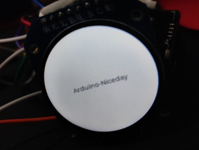
烧录代码后的实验效果
2.跑lvgl库自身提供的示例代码
lvgl自身提供了很多的example,比arduino GFX库的LVGL的示例程序要丰富得多,所以我们需要把lvgl自身提供的示例程序跑起来,这样才更有利于学习lvgl。
上图是一个表盘的示例程序。
百度查找到类似解决方法
答案就是把相关的文件或文件夹复制到lvgl/src路径下,然后再去编译。
这是一个编译的问题,修改CMake肯定也可以解决。先不研究,先用这种简单的挪动文件夹的方式搞定功能,先体验一把再说。
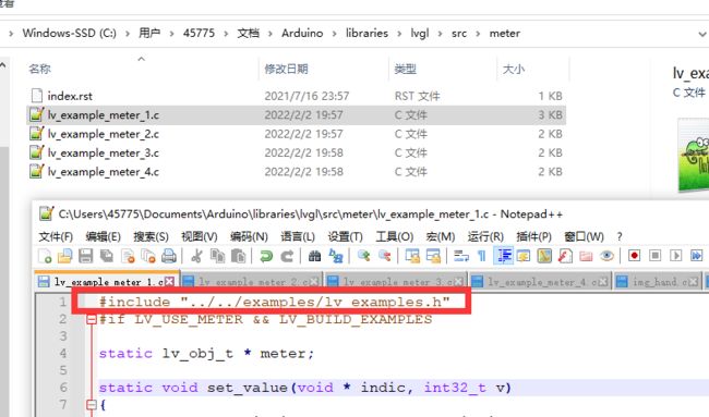
我把lvgl/examples文件夹内的assets、meter和img文件夹都复制了过来,
遇到编译报错,修改了一下头文件包含就解决了,
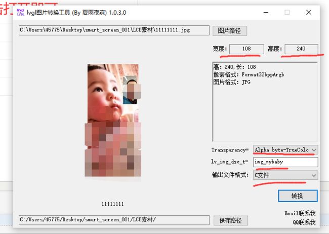
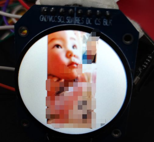
img文件夹里的东西被我删除了,修改了其代码,用于配套显示我自制的图片。
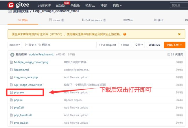
LVGL图片转C文件工具=》 https://gitee.com/gzmarkz/Lvgl_image_convert_tool
使用展示:
将转换后的C文件放置在asserts文件夹内即可。
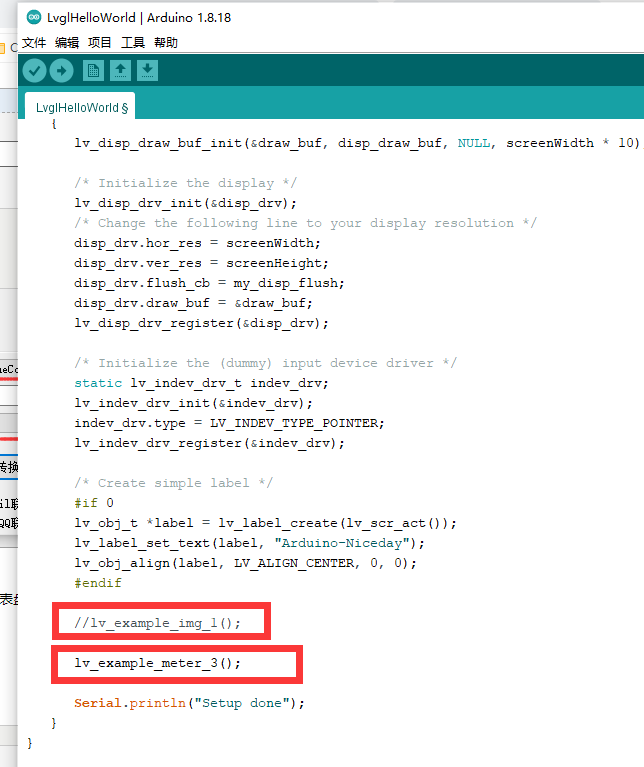
直接在本篇的原工程内调用俩函数,即可显示不同的效果了。一个显示我的自制图片,一个显示lvgl的表盘例子。
实验效果:
存在的问题,我看别人的表盘示例效果,有俩指针,是会动的,我的指针没动。
看代码,应该是创建动画的这部分没达到预期效果。动画功能,在LVGL移植后,未能正常工作。
.


