记录:指针仪表盘视觉读取项目的学习过程
今天在整理电脑文件时,发现了好久前做的一个小项目,是关于指针仪表盘读取的,也是当时导师布置给我的一个任务,我决定梳理下,写个博客,也方便以后自己若有需要时可以随时查找。
本篇博客记录了我开发这个小项目的全部过程,以及对于需求的改变、方案的更新等等。PS:用到的都是传统的机器视觉方法,不涉及深度学习方面的知识。仅供参考
本文内容
- 方案1.0
-
- 一.任务说明(仅关于视觉部分)
- 二.方案内容
- 方案2.0
-
- 一.方案描述
- 二.程序思路
- 三.遇到的问题
- 四.解决思路
- 五.源码
- 方案3.0
-
- 一.问题描述
- 二.解决方法
- 三.源码
- PS
方案1.0
一.任务说明(仅关于视觉部分)
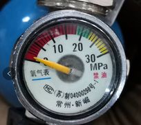
要求:可精确稳定的识别出表头中的数据,精确到1MPa。
场景:①对方就唯一的这种表,也就是对象是固定的。
②有一个检测箱,箱里有摄像头和其他硬件可远程通讯,压力表连同被测罐连在一起,放到检测箱里固定位置度数及检查其他内容。也就是读表只是它的一部分工作。
③那么每个表和摄像头之间位置是相对固定的。
(其他关于界面、硬件部分需求这里就不介绍了)
二.方案内容
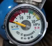

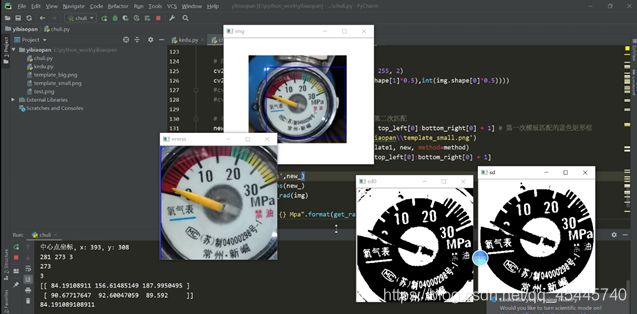
一开始接到的图片就这么一张,我首先想到的是用opencv自带的模板匹配的方法,将刻度盘作为我的模板,去寻找图片中的ROI区域,很显然,在当时只有一种图片的情况下,效果简直太棒,然而却忽视了一个重要的问题。
先看下当时的效果:


关于模板匹配参考的资料:
https://blog.csdn.net/wzz18191171661/article/details/91345166
方案2.0
一.方案描述
在方案1.0中,提到了当时我忽视了一个重要的问题,就是模板匹配这个方法,要求你的模板大小尺寸必须和你要匹配的图像中的目标对象尺寸差不多,就好比你的模板是300×300的,而你要匹配的图像ROI区域可能只有100×100或者900×900的大小,这样模板匹配的方法就行不通了。过了几天,导师又给了我第二批的图片。
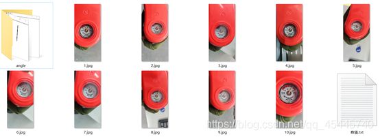
(上面这批图片都是1840*4000的大图片,ROI区域很大)
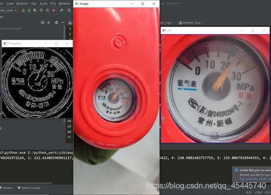
思考了下,突然想到可以使用多尺度模板匹配的方法,所谓多尺度,比如说我这里选取的模板大小就是300×300的,对于图片的1840×4000的超大图片,我把它一步一步的缩小或者放大(这里是缩小),就这样每次缩小图片的一点点,缩小一次就拿我的300×300模板去匹配一次,虽然有点笨且运行速度相比于之前慢了些,但能解决问题就行,果然这种方法还是可靠的。
效果如下:
二.程序思路
1.需要一个仪表盘的模板,要正,精确,清楚,标定好这个模板的刻度的像素坐标,圆心的像素坐标等等,用这个模板去匹配相机拍摄到的对象,这里运行opencv自带的特征匹配。(采用多尺度模板匹配的方法)
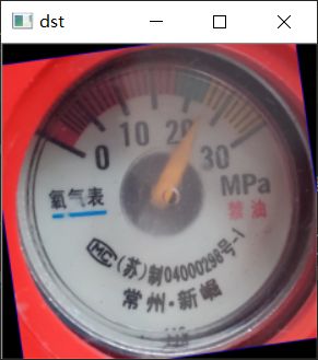
2.提取到ROI区域后,对于图像是否正,还需要进行旋转矫正,观察发现刻度盘中氧气下面的蓝色线的特征,以此为基准来获取当前刻度盘的旋转角度。(这里默认刻度盘是180°内的倾斜,总不至于刻度盘是颠倒的吧)
(图像矫正时还考虑到了用离散傅里叶矫正,因为曾经在看书的时候书上说离散傅里叶对于图像处理的一个重要应该就是可以判断当前图片的倾斜角度,后发现不行,参考博客:
https://blog.csdn.net/wsp_1138886114/article/details/83374333
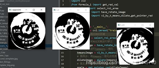
3.采用无监督学习的Kmeans算法,鉴于图像的复杂度,提取出每个刻度不太容易,观察发现因为刻度和指针的颜色肯定和周围不同,至于到底是什么颜色我不需要管,交给Kmeans就行了,只要设定最后的聚类种类为2,返回聚类后的结果获得两个阈值点,然后以这个为阈值,把图像进行二值化分割,图像进行二值化分割后,这里有没有刻度反而对我不重要了,因为在模板中我已经将所有的刻度都标定好了,这里只需要读取当前指针的位置就行了。(采用Kmeans二值化后,指针是白色的,采用图像的颜色反转,将指针变成黑色,从而进行后续操作),这里使用形态学处理会让效果更好,https://segmentfault.com/a/1190000015650320
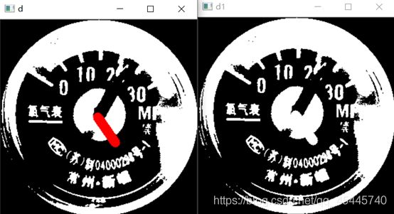
4.表盘读取的方法:以表盘中心为起点,画一条线段,进行旋转,这条直线的粗细程度要看当前指针的粗细程度,让这条直线进行旋转,当它与指针重合最多的时候,就是该位置,读取当前的角度值,再去我之前设置好了的刻度表里面去读数就好了
三.遇到的问题
①当时使用多尺度模板匹配的方法,虽然可以很精确地截取到图片中的ROI区域,但带来了另一个问题,就是提取到的ROI区域这个刻度圆盘,它发生了旋转,更为要命的是有的刻度圆盘已经发生了畸形。
②在图像处理中,对于正常的旋转矫正,只需要知道当前的倾斜角度就可以旋转了;而对于畸形的这种,则需要透视矫正,比较麻烦。
③先解决倾斜角度的旋转,首先如何获取这个角度的值是一个问题,正常的方法是使用霍夫直线检测来提取直线的倾斜角度,根据我的观察发现,无论是什么情况,刻度圆盘中氧气表三个字下面的蓝色线段,很明显且清楚,于是从这里下手。
四.解决思路
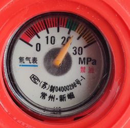
上面这幅图是仪表盘比较清除的图像,
紧接着,如何识别出这个蓝色的线段呢?若采用霍夫直线检测,则会检测出很多的直线出来,到时候这个筛选标准又是什么?又是一个问题。某日在逛知乎的时候,突然看到了一篇文章
https://zhuanlan.zhihu.com/p/67930839(RGB、HSV和HSL颜色空间)
其中有一段话:RGB颜色空间更加面向于工业,而HSV更加面向于用户,大多数做图像识别这一块的都会运用HSV颜色空间,因为HSV颜色空间表达起来更加直观。这时候想到,这个蓝色在整个ROI区域中都是独一无二的,何不把它提取出来呢?关于获取图片中指定的颜色部分,参考了这篇博客
https://blog.csdn.net/qq_40456669/article/details/93375709

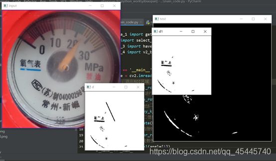
可以看到蓝色的HSV值,编程后的效果如下:效果直呼感人!
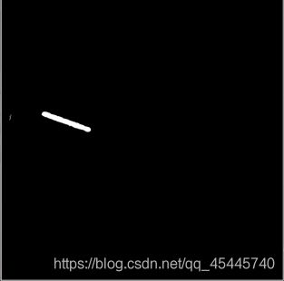
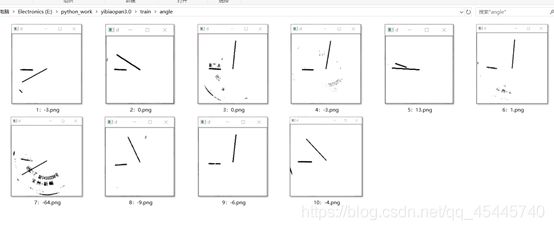
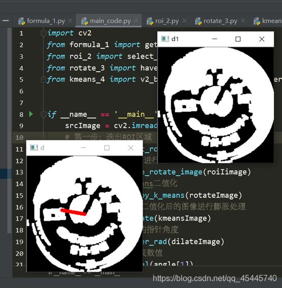
进入下一个问题,怎么知道这个线段的倾斜角度呢?这里我采用了指针刻度读取的办法,在该图的中心画一个线段,旋转360°,先把这个图取反,然后读取每旋转一度画个指针与该度数方向重合的点的数量,读取重合点的数量最多的时候的度数值,经过运算就可以知道这条线段的倾斜角度,也就是整个ROI区域的旋转角度,解决!
而对于畸形,透视矫正,当时并没有考虑,这里先等下说,先看下程序效果:

五.源码
程序细节:
选取特征匹配的模板:second_template
300*300
代码:
1_formulas 角度转数值的计算公式
2_roi 提取ROI区域,返回框选好了的ROI区域img_2
3_rotate 将图像矫正 返回矫正好了的图像 img_3
4_kmeans 采用kmeans二值化处理
formula_1.py
import math

center = [151 , 147]  # 模板template1指针刻度盘的圆心位置

# 刻度盘上每个数值的坐标
a = {0:(68,91),1:(76,78),2:(80,75),3:(83,71),4:(87,68),5:(91,65),6:(96,61),7:(102,57),
     8:(107,53),9:(113,52),10:(121,50),11:(126,47),12:(132,46),13:(139,45),14:(145,44),
     15:(152,45),16:(159,45),17:(166,46),18:(172,47),19:(179,49),20:(186,51),21:(192,54),
     22:(198,57),23:(204,61),24:(210,65),25:(215,69),26:(220,74),27:(224,79),28:(229,84),
     29:(233,90),30:(238,97)}

count = 0
result = {}

# 计算指针刻度盘中每个刻度的角度
for k ,v in a.items():
    r = math.acos((v[0]-center[0])/((v[0]-center[0])**2 + (v[1]-center[1])**2)**0.5) # 得到弧度值
    r = r*180/math.pi  # 将弧度值转化为角度值
    a[k] = r
    if k != 31:
        r=360-r
        # print(k, r)
    result[k]=r
    count+=1

print(result)

result_list = result.items()
lst = sorted(result_list,key=lambda x:x[1])

# 读取指针所指的刻度,稍微大一点的整数刻度,比如20,30,40等等
def get_next(c):
    l = len(lst) # 10
    n = 0
    for i in range(len(lst)):
        if lst[i][0] == c:
            n = i+1
            if n == l:
                n = 0
            break
    return lst[n]


# 参数rad:表示当前指针所指的角度。角度是以右边x轴为0刻度,顺时针旋转读取
def get_rad_val(rad):
    old=None
    for k, v in lst:
        # print(k,v)
        if rad > v :
            old = k
    print(old)
    r = result[old]
    d = rad-r
    nx = get_next(old)
    print(1*abs(d/(nx[1] - r)))
    print(nx)
    t = old+1*abs(d/(nx[1] - r))
    print(t)
    return t
roi_2.py
"""第一第二步:该程序的目的是用模板匹配到图片中的ROI区域"""
import numpy as np
import argparse
import glob
import imutils
import cv2

def select_roi_area(img):
    ap = argparse.ArgumentParser()
    ap.add_argument("-v", "--visualize", help="Flag indicating whether or not to visualize each iteration")
    args = vars(ap.parse_args())

    # 读取模板图片
    template = cv2.imread("second_template.jpg")
    # 转换为灰度图片
    template = cv2.cvtColor(template, cv2.COLOR_BGR2GRAY)
    # 执行边缘检测
    template = cv2.Canny(template, 50, 200)
    (tH, tW) = template.shape[:2]
    # 显示模板
    cv2.imshow("Template", template)

    # 遍历所有的图片寻找模板
    # 读取测试图片并将其转化为灰度图片
    gray = cv2.cvtColor(img, cv2.COLOR_BGR2GRAY)
    found = None

    # 循环遍历不同的尺度
    for scale in np.linspace(0.2, 1.0, 20)[::-1]:
        # 根据尺度大小对输入图片进行裁剪
        resized = imutils.resize(gray, width = int(gray.shape[1] * scale))
        r = gray.shape[1] / float(resized.shape[1])

        # 如果裁剪之后的图片小于模板的大小直接退出
        if resized.shape[0] < tH or resized.shape[1] < tW:
            break

        # 首先进行边缘检测,然后执行模板检测,接着获取最小外接矩形
        edged = cv2.Canny(resized, 50, 200)
        result = cv2.matchTemplate(edged, template, cv2.TM_CCOEFF)
        (_, maxVal, _, maxLoc) = cv2.minMaxLoc(result)

        # 结果可视化
        if args.get("visualize", False):
            # 绘制矩形框并显示结果
            clone = np.dstack([edged, edged, edged])
            cv2.rectangle(clone, (maxLoc[0], maxLoc[1]), (maxLoc[0] + tW, maxLoc[1] + tH), (0, 0, 255), 2)
            cv2.imshow("Visualize", clone)
            cv2.waitKey(0)

        # 如果发现一个新的关联值则进行更新
        if found is None or maxVal > found[0]:
            found = (maxVal, maxLoc, r)

    # 计算测试图片中模板所在的具体位置,即左上角和右下角的坐标值,并乘上对应的裁剪因子
    (_, maxLoc, r) = found
    (startX, startY) = (int(maxLoc[0] * r), int(maxLoc[1] * r))
    (endX, endY) = (int((maxLoc[0] + tW) * r), int((maxLoc[1] + tH) * r))

    # 绘制并显示结果
    cv2.rectangle(img, (startX, startY), (endX, endY), (255, 0, 0), 2)
    cv2.imshow("Image", cv2.resize(img,(int(img.shape[1]*0.2),int(img.shape[0]*0.2))))
    new_ = img[startY:endY + 1, startX:endX + 1, ]
    img_2 = cv2.resize(new_,(int(new_.shape[1]*0.5),int(new_.shape[0]*0.5)))
    cv2.imshow("roi",img_2)
    cv2.waitKey(0)
    cv2.destroyAllWindows()

    return img_2
rotate_3.py
# 第三步:图像的矫正
import cv2
import numpy as np
from math import cos, pi, sin

def get_rotate_rad(img):
    '''获取角度'''
    shape = img.shape
    c_y, c_x= int(shape[0] / 2), int(shape[1] / 2)
    x1=c_x+c_x*0.8
    src = img.copy()

    freq_list = []
    for i in range(361):
        x = (x1 - c_x) * cos(i * pi / 180) + c_x
        y = (x1 - c_x) * sin(i * pi / 180) + c_y
        temp = src.copy()
        cv2.line(temp, (c_x, c_y), (int(x), int(y)+14), (0, 0, 255), thickness=2)
        t1 = img.copy()
        t1[temp[:, :] == 255] = 255
        c = img[temp[:, :] == 255]
        points = c[c == 255]
        freq_list.append((len(points), i))
        cv2.imshow('d', temp)
        cv2.imshow('d1', t1)
        cv2.waitKey(1)
    print(freq_list)
    print('当前角度:',max(freq_list, key=lambda x: x[0]),'度')
    cv2.destroyAllWindows()
    return max(freq_list)


def have_rotate_image(src):
    cv2.namedWindow("input", cv2.WINDOW_AUTOSIZE)
    cv2.imshow("input", src)
    """
    提取图中的蓝色部分
    """
    hsv = cv2.cvtColor(src, cv2.COLOR_BGR2HSV)
    low_hsv = np.array([100,43,46])
    high_hsv = np.array([124,255,255])
    mask = cv2.inRange(hsv,lowerb=low_hsv,upperb=high_hsv)
    cv2.imshow("test",mask)

    no_mask = 255 - mask  # 颜色取反,将指针变为黑色

    n_mask = cv2.resize(no_mask,(int(no_mask.shape[1]*0.5),int(no_mask.shape[0]*0.5)))

    a = get_rotate_rad(n_mask)
    print(a[1])

    angle = a[1] - 180
    # angle为正,逆时针旋转;为负,顺时针旋转
    print("当前ROI旋转的角度:{}".format(angle))

    matRotate = cv2.getRotationMatrix2D((src.shape[1]*0.5,src.shape[0]*0.5),angle,1)
    dst = cv2.warpAffine(src,matRotate,(src.shape[1],src.shape[0]))

    img_3 = cv2.resize(dst,(int(dst.shape[1]*0.5),int(dst.shape[0]*0.5)))

    cv2.imshow("dst",img_3)
    cv2.waitKey(0)
    cv2.destroyAllWindows()

    return img_3
kmeans_4.py
import numpy as np
import cv2
from sklearn.cluster import KMeans
from sklearn.utils import shuffle
from math import cos, pi, sin


def v2_by_k_means(img):
    '''使用k-means二值化'''
    original_img = np.array(img, dtype=np.float64) # original_img与img格式一样,但为白色
    src = original_img.copy()
    delta_y = int(original_img.shape[0] * (0.4))
    delta_x = int(original_img.shape[1] * (0.4))
    original_img = original_img[delta_y:-delta_y, delta_x:-delta_x]
    h, w, d = src.shape
    print(w, h, d)
    dts = min([w, h])
    print(dts)
    r2 = (dts / 2) ** 2
    c_x, c_y = w / 2, h / 2
    a: np.ndarray = original_img[:, :, 0:3].astype(np.uint8)
    # 获取尺寸(宽度、长度、深度)
    height, width = original_img.shape[0], original_img.shape[1]
    depth = 3
    print(depth)
    image_flattened = np.reshape(original_img, (width * height, depth))
    '''K-Means算法'''
    image_array_sample = shuffle(image_flattened, random_state=0)# 随机打乱image_flattened中的元素
    estimator = KMeans(n_clusters=2, random_state=0) # 生成两个质心
    estimator.fit(image_array_sample)
    '''
    为原始图片的每个像素进行类的分配。
    '''
    src_shape = src.shape
    new_img_flattened = np.reshape(src, (src_shape[0] * src_shape[1], depth))
    cluster_assignments = estimator.predict(new_img_flattened)
    '''
    我们建立通过压缩调色板和类分配结果创建压缩后的图片
    '''
    compressed_palette = estimator.cluster_centers_
    print(compressed_palette) # 收敛到的质心位置
    a = np.apply_along_axis(func1d=lambda x: np.uint8(compressed_palette[x]), arr=cluster_assignments, axis=0)
    img = a.reshape(src_shape[0], src_shape[1], depth)
    print(compressed_palette[0, 0])
    threshold = (compressed_palette[0, 0] + compressed_palette[1, 0]) / 2
    img[img[:, :, 0] > threshold] = 255
    img[img[:, :, 0] < threshold] = 0
    cv2.imshow('sd0', img)
    # 下一步因为指针仪表盘是圆形,所以去除掉圆以外的干扰因素
    for x in range(w):
        for y in range(h):
            distance = ((x - c_x) ** 2 + (y - c_y) ** 2)
            if distance > r2:
                pass
                img[y, x] = (255, 255, 255)
    cv2.imshow('sd', img)
    img = 255 - img
    cv2.imshow('opposite',img)
    cv2.waitKey(0)
    cv2.destroyAllWindows()
    return img


def dilate(img):
    '''将Kmeans二值化后的图像进行膨胀处理'''
    kernel = np.ones((5, 5), np.uint8)
    dilation = cv2.dilate(img, kernel, iterations=1)
    return dilation


def get_pointer_rad(img):
    '''获取角度'''
    shape = img.shape
    c_y, c_x, depth = int(shape[0] / 2), int(shape[1] / 2), shape[2]
    x1=c_x+c_x*0.4
    src = img.copy()

    freq_list = []
    for i in range(361):
        x = (x1 - c_x) * cos(i * pi / 180) + c_x
        y = (x1 - c_x) * sin(i * pi / 180) + c_y
        temp = src.copy()
        cv2.line(temp, (c_x, c_y), (int(x), int(y)), (0, 0, 255), thickness=6)
        t1 = img.copy()
        t1[temp[:, :, 2] == 255] = 255
        c = img[temp[:, :, 2] == 255]
        points = c[c == 0]
        freq_list.append((len(points), i))
        cv2.imshow('d', temp)
        cv2.imshow('d1', t1)
        cv2.waitKey(1)
    print('当前角度:',max(freq_list, key=lambda x: x[0]),'度')
    cv2.destroyAllWindows()

    return max(freq_list, key=lambda x: x[0])
main_code.py
import cv2
from formula_1 import get_rad_val
from roi_2 import select_roi_area
from rotate_3 import have_rotate_image
from kmeans_4 import v2_by_k_means,dilate,get_pointer_rad


if __name__ == '__main__':
    srcImage = cv2.imread("train/3.jpg")

    # 第一步:选出ROI区域
    roiIimage = select_roi_area(srcImage)

    # 第二步:对ROI区间进行矫正
    rotateImage = have_rotate_image(roiIimage)

    # 第三步:进行kemeans二值化
    kmeansImage = v2_by_k_means(rotateImage)

    # 第四步:将Kmeans二值化后的图像进行膨胀处理
    dilateImage = dilate(kmeansImage)

    # 第五步:获取当前的指针角度
    angle = get_pointer_rad(dilateImage)

    # 第六步:角度转换成数值
    value = get_rad_val(angle[1])

    print("当前刻度盘的数值是:{}".format(value))
PS:后来与老师的沟通中,才了解到实际的工作环境中,摄像头能够保证与刻度盘的平面互相平行,这样一来就不存在刻度盘的畸形这种情况了,就是说不需要进行透视矫正了。
方案3.0
一.问题描述
虽然否决了图像畸形不需要透视矫正,但又有了个问题,因为给的那十张图片场景都很单一,如果放在更为复杂的环境当中,或者与很多的刻度盘放在一起,那还能准确的找到ROI区域吗?一开始我认为,多尺度模板匹配可以很好的解决这些问题,也没太在意。不过后来想想还是去测试一下吧,于是我简单的P了几张图片,如下:

然后当我使用多尺度模板匹配的方法去寻找ROI区域时,发现根本找不到ROI区域。
二.解决方法
①查了相关资料,总结:若多尺度模板匹配的方法效果不好的话,可以考虑关键点匹配法,比较经典的关键点检测算法包括SIFT和SURF等,主要的思路是首先通过关键点检测算法获取模板和测试图片中的关键点;然后使用关键点匹配算法处理即可,这些关键点可以很好的处理尺度变化、视角变换、旋转变化、光照变化等,具有很好的不变性。
查询资料:https://blog.csdn.net/zhuisui_woxin/article/details/84400439
(基于FLANN的匹配器(FLANN based Matcher)描述特征点)精确完成了特征匹配的任务!
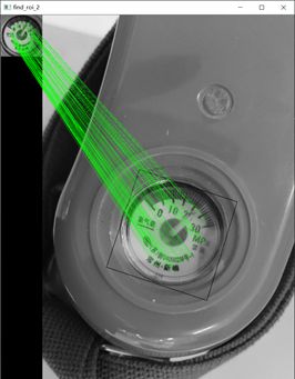
意外发现:之前在方案2.0中说到了,获取ROI区域的旋转角度时,费了工夫,然而当我使用基于FLANN的匹配器的时候,发现框选的部分,自动将那个旋转角度的多边形给框选了出来:
②但接着又遇到一个新问题,python的PIL库自带的方法只能进行矩形的切割,但这里是多边形各个顶点的坐标,如何对现有的图片按照这个多边形进行切割呢?首先可以确定的是,我肯定已经获取到了这个四边形的四个顶点坐标,否则不会框选出来,依照这个思路,参考这篇文章:http://www.6tie.net/p/1177178.html (使用Opencv python从Image中裁剪凹面多边形)
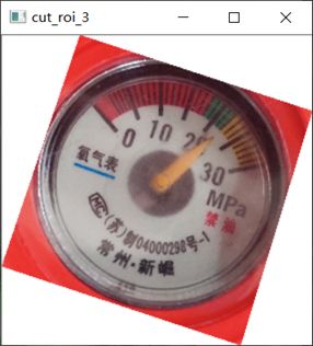
完美切割出来,
进入下一个步骤,将这个裁剪出来的ROI区域进行透视变换,参考资料:
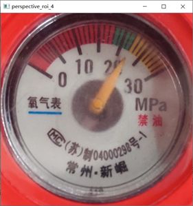
https://blog.csdn.net/t6_17/article/details/78729097。博客中是自己写的四个点坐标,这里因为上一步已经获取到了四个顶点的坐标,所以这里直接进行透视变换,因为我选的模板是300*300的正方形,所以我把这个ROI区域也透视变换为正方形的图片,方便后面的进一步运算,透视变换的结果如下:
 至此,下面的操作就和之前的方案一样了:


三.源码
程序细节:
选取特征匹配的模板:second_template
300*300
代码:
第一步:指针数值的算法理论 formula_1
第二步:基于FLANN匹配roi区域 find_roi_FLANN_2
第三步:在原图上剪切出需要的多边形roi区域
cut_roi_3
第四步:进行透视变换将多边形转化为正方形(为了与模板一样方便后面运算)perspective_roi_4
第五步:kmeans_5
formula_1.py
import math

center = [151 , 147]  # 模板template1指针刻度盘的圆心位置

# 刻度盘上每个数值的坐标
a = {0:(68,91),1:(76,78),2:(80,75),3:(83,71),4:(87,68),5:(91,65),6:(96,61),7:(102,57),
     8:(107,53),9:(113,52),10:(121,50),11:(126,47),12:(132,46),13:(139,45),14:(145,44),
     15:(152,45),16:(159,45),17:(166,46),18:(172,47),19:(179,49),20:(186,51),21:(192,54),
     22:(198,57),23:(204,61),24:(210,65),25:(215,69),26:(220,74),27:(224,79),28:(229,84),
     29:(233,90),30:(238,97)}

count = 0
result = {}

# 计算指针刻度盘中每个刻度的角度
for k ,v in a.items():
    r = math.acos((v[0]-center[0])/((v[0]-center[0])**2 + (v[1]-center[1])**2)**0.5) # 得到弧度值
    r = r*180/math.pi  # 将弧度值转化为角度值
    a[k] = r
    if k != 31:
        r=360-r
        # print(k, r)
    result[k]=r
    count+=1

# print(result)
# {0: 214.00749241973224, 1: 222.61405596961117, 2: 225.40066325579215, 3: 228.17983011986422,
# 4: 230.9881483757755, 5: 233.8067926944353, 6: 237.39966642630975, 7: 241.43416320625343,
# 8: 244.91640599380906, 9: 248.19859051364818, 10: 252.81429385577522, 11: 255.9637565320735,
# 12: 259.3460974000615, 13: 263.2901631922431, 14: 266.6661493384634, 15: 270.56170533256653,
# 16: 274.4846060095446, 17: 278.44752724790845, 18: 281.85977912094796, 19: 285.94539590092285,
# 20: 290.03101268089773, 21: 293.79077386577717, 22: 297.5745639596944, 23: 301.64465903709254,
# 24: 305.735476014867, 25: 309.36931724236473, 26: 313.38646106711883, 27: 317.0309142368531,
# 28: 321.0724564072077, 29: 325.1959882472868, 30: 330.113473059576}

result_list = result.items()
lst = sorted(result_list,key=lambda x:x[1])


# 读取指针所指的刻度,稍微大一点的整数刻度,比如20,30,40等等
def get_next(c):
    l = len(lst) # 10
    n = 0
    for i in range(len(lst)):
        if lst[i][0] == c:
            n = i+1
            if n == l:
                n = 0
            break
    return lst[n]


# 参数rad:表示当前指针所指的角度。角度是以右边x轴为0刻度,顺时针旋转读取

def get_rad_val(rad):
    old=None
    for k, v in lst:
        # print(k,v)
        if rad > v :
            old = k
    # print(old)
    r = result[old]
    d = rad-r
    nx = get_next(old)
    # print(1*abs(d/(nx[1] - r)))
    # print(nx)
    t = old+1*abs(d/(nx[1] - r))
    # print(t)

    return t
find_roi_FLANN_2.py
"""第一第二步:该程序的目的是用模板匹配到图片中的ROI区域"""
# 基于FLANN的匹配器(FLANN based Matcher)定位图片
import numpy as np
import cv2

def find_roi(template,target):
    MIN_MATCH_COUNT = 10  # 设置最低特征点匹配数量为10
    #创建sift检测器
    sift = cv2.xfeatures2d.SIFT_create()
    #使用SIFT查找关键点和描述符(keypoints和descriptors)
    kp1, des1 = sift.detectAndCompute(template, None) #计算出图像的关键点和sift特征向量
    kp2, des2 = sift.detectAndCompute(target, None)

    # 创建设置FLANN匹配
    FLANN_INDEX_KDTREE = 0 # FLANN 参数
    index_params = dict(algorithm=FLANN_INDEX_KDTREE, trees=5)
    search_params = dict(checks=50)
    flann = cv2.FlannBasedMatcher(index_params, search_params) # 使用FlannBasedMatcher 寻找最近邻近似匹配
    matches = flann.knnMatch(des1, des2, k=2) # 使用knnMatch匹配处理,并返回匹配matches
    # 通过coff系数来决定匹配的有效关键点数量
    good = [] # 0.1 0.7  0.8  参数可以自己修改进行测试
    # 舍弃大于0.7的匹配
    # 还是通过描述符的距离进行选择需要的点
    for m, n in matches:
        if m.distance < 0.7 * n.distance:
            good.append(m)
    if len(good) > MIN_MATCH_COUNT:
        # 获取关键点的坐标
        src_pts = np.float32([kp1[m.queryIdx].pt for m in good]).reshape(-1, 1, 2)
        dst_pts = np.float32([kp2[m.trainIdx].pt for m in good]).reshape(-1, 1, 2)
        # 计算变换矩阵和MASK
        M, mask = cv2.findHomography(src_pts, dst_pts, cv2.RANSAC, 5.0)#找到两个平面之间的转换矩阵
        matchesMask = mask.ravel().tolist()
        h, w = template.shape
        # 使用得到的变换矩阵对原图像的四个角进行变换,获得在目标图像上对应的坐标
        pts = np.float32([[0, 0], [0, h - 1], [w - 1, h - 1], [w - 1, 0]]).reshape(-1, 1, 2)
        dst = cv2.perspectiveTransform(pts, M)
        cv2.polylines(target, [np.int32(dst)], True, 0, 2, cv2.LINE_AA)
        # cv2.drawContours(target, [np.int32(dst)], -1, (0, 255, 0), 3)
    else:
        print("Not enough matches are found - %d/%d" % (len(good), MIN_MATCH_COUNT))
        matchesMask = None
    draw_params = dict(matchColor=(0, 255, 0),
                       singlePointColor=None,
                       matchesMask=matchesMask,
                       flags=2)
    result = cv2.drawMatches(template, kp1, target, kp2, good, None, **draw_params) #进行画图操作
    result = cv2.resize(result,(int(result.shape[1]*0.3),int(result.shape[0]*0.3)))
    cv2.imshow("find_roi_2", result)

    cv2.waitKey(0)

    return result,dst
cut_roi_3.py
# 多边形的切割
import numpy as np
import cv2

def polylines_cut(img,pts):
    ## (1) 裁剪边界矩形
    rect = cv2.boundingRect(pts)
    x,y,w,h = rect
    croped = img[y:y+h, x:x+w].copy()

    ## (2) 生成掩膜
    pts = pts - pts.min(axis=0)
    mask = np.zeros(croped.shape[:2], np.uint8)
    cv2.drawContours(mask, [pts], -1, (255, 255, 255), -1, cv2.LINE_AA)

    ## (3) 反运算
    dst = cv2.bitwise_and(croped, croped, mask=mask)

    ## (4) 添加白色背景
    bg = np.ones_like(croped, np.uint8)*255
    cv2.bitwise_not(bg,bg, mask=mask)
    dst2 = bg + dst
    cv2.imshow("cut_roi_3", cv2.resize(dst2,(int(dst2.shape[1]*0.3),int(dst2.shape[0]*0.3))))

    cv2.waitKey(0)

    return dst2,pts
perspective_roi_4.py
import numpy as np
import cv2


def perspective_roi(cut_img,src_img,points):
    if cut_img.shape[0]>cut_img.shape[1]:
        L = cut_img.shape[0]
    else:
        L = cut_img.shape[1]
    print("L的取值:",L)
    # 下面进行透视变换
    src = np.float32([[np.int(points[0][0][0]),np.int(points[0][0][1])],[np.int(points[1][0][0]),np.int(points[1][0][1])],
                     [np.int(points[2][0][0]),np.int(points[2][0][1])],[np.int(points[3][0][0]),np.int(points[3][0][1])]])
    dst = np.float32([[0, 0], [0, L], [L, L], [L, 0]])
    m = cv2.getPerspectiveTransform(src, dst)
    result = cv2.warpPerspective(src_img, m, (L, L))
    result = cv2.resize(result, (int(result.shape[1] * 0.5), int(result.shape[0] * 0.5)))

    cv2.imshow("perspective_roi_4", result)

    goal_result = cv2.resize(result,(300,300))

    cv2.waitKey(0)

    return goal_result
xiugai_kmeans_5.py
import numpy as np
import cv2
from sklearn.cluster import KMeans
from sklearn.utils import shuffle
from math import cos, pi, sin


def v2_by_k_means(img):
    '''使用k-means二值化'''
    original_img = np.array(img, dtype=np.float64) # original_img与img格式一样,但为白色
    src = original_img.copy() # 300*300
    delta_y = int(original_img.shape[0] * (0.4)) #120
    delta_x = int(original_img.shape[1] * (0.4)) #120
    original_img = original_img[delta_y:-delta_y, delta_x:-delta_x] #60*60
    # print("delta_y:{},delta_x:{},original_img:{}".format(delta_y,delta_x,original_img.shape)
    h, w, d = src.shape
    # print("h,w,d:",h,w,d)
    dts = min([w, h])
    r2 = (dts / 2) ** 2
    c_x, c_y = w / 2, h / 2
    a: np.ndarray = original_img[:, :, 0:3].astype(np.uint8)
    # 获取尺寸(宽度、长度、深度)
    height, width = original_img.shape[0], original_img.shape[1]
    depth = 3
    image_flattened = np.reshape(original_img, (width * height, depth))
    '''K-Means算法'''
    image_array_sample = shuffle(image_flattened, random_state=0)# 随机打乱image_flattened中的元素
    estimator = KMeans(n_clusters=2, random_state=0) # 生成两个质心
    estimator.fit(image_array_sample)
    '''
    为原始图片的每个像素进行类的分配。
    '''
    src_shape = src.shape
    new_img_flattened = np.reshape(src, (src_shape[0] * src_shape[1], depth))
    cluster_assignments = estimator.predict(new_img_flattened)
    '''
    我们建立通过压缩调色板和类分配结果创建压缩后的图片
    '''
    compressed_palette = estimator.cluster_centers_
    print("收敛到的质心位置:",compressed_palette) # 收敛到的质心位置
    a = np.apply_along_axis(func1d=lambda x: np.uint8(compressed_palette[x]), arr=cluster_assignments, axis=0)
    img = a.reshape(src_shape[0], src_shape[1], depth)
    threshold = (compressed_palette[0, 0] + compressed_palette[1, 0]) / 2
    img[img[:, :, 0] > threshold] = 255
    img[img[:, :, 0] < threshold] = 0
    cv2.imshow('sd0', img) # 300*300
    # 下一步因为指针仪表盘是圆形,所以去除掉圆以外的干扰因素
    for x in range(w):
        for y in range(h):
            distance = ((x - c_x) ** 2 + (y - c_y) ** 2)
            if distance > r2:
                pass
                img[y, x] = (255, 255, 255)
    cv2.imshow('sd', img)
    img = 255 - img
    cv2.imshow('opposite',img)
    cv2.waitKey(0)
    cv2.destroyAllWindows()

    return img


def dilate(img):
    '''将Kmeans二值化后的图像进行膨胀处理'''
    kernel = np.ones((3, 3), np.uint8)
    dilation = cv2.dilate(img, kernel, iterations=1)
    return dilation


'''下面才是刻度盘读取的核心'''
def get_pointer_rad(img):
    '''获取角度'''
    shape = img.shape
    c_y, c_x, depth = int(shape[0] / 2), int(shape[1] / 2), shape[2]
    # c_y,c_x表示画的指针线段的起点(圆心)
    x1=c_x+c_x*0.3
    src = img.copy()
    freq_list = []
    for i in range(361):
        # 下面的x,y是指针线段的终点坐标
        x = (x1 - c_x) * cos(i * pi / 180) + c_x
        y = (x1 - c_x) * sin(i * pi / 180) + c_y
        temp = src.copy()
        cv2.line(temp, (c_x-2, c_y-2), (int(x), int(y)), (0, 0, 255), thickness=14)
        t1 = img.copy()
        t1[temp[:, :, 2] == 255] = 255
        c = img[temp[:, :, 2] == 255]
        points = c[c == 0] # 0表示黑色,即旋转指针中重合黑色的点最多的角度
        freq_list.append((len(points), i))
        cv2.imshow('d', temp)
        cv2.imshow('d1', t1)
        cv2.waitKey(0)
    print('当前角度:',max(freq_list, key=lambda x: x[0]),'度')
    print(max(freq_list, key=lambda x: x[0]))
    return max(freq_list, key=lambda x: x[0])
main_code.py
import cv2
import numpy as np
from formula_1 import get_rad_val
from find_roi_FLANN_2 import find_roi
from cut_roi_3 import polylines_cut
from perspective_roi_4 import perspective_roi
from xiugai_kmeans_5 import v2_by_k_means,dilate,get_pointer_rad


if __name__ == '__main__':
    template = cv2.imread("second_template.jpg",0)
    target = cv2.imread('train/5.jpg')
    target_gray = cv2.cvtColor(target,cv2.COLOR_BGR2GRAY)  # 目标图像
    cv2.imshow("src",template)

    #第一步:基于FLANN匹配roi区域
    find_roi_image,points = find_roi(template,target_gray)

    #第二步:在原图上剪切出需要的多边形roi区域
    pts = np.array([[np.int(points[0][0][0]),np.int(points[0][0][1])],[np.int(points[1][0][0]),np.int(points[1][0][1])],
                    [np.int(points[2][0][0]),np.int(points[2][0][1])],[np.int(points[3][0][0]),np.int(points[3][0][1])]])
    cut_roi_image,keypoints = polylines_cut(target,pts)

    #第三步:进行透视变换将多边形转化为正方形(为了与模板一样方便后面运算)perspective_roi_4
    jiaozheng_image = perspective_roi(cut_roi_image,target,points)

    #第四步:kmeans_5
    kmeansImage = v2_by_k_means(jiaozheng_image)

    # 第四步:将Kmeans二值化后的图像进行膨胀处理
    # dilateImage = dilate(kmeansImage)

    # 第五步:获取当前的指针角度
    angle = get_pointer_rad(kmeansImage)

    # 第六步:角度转换成数值
    value = get_rad_val(angle[1])
    print("第5张图片的刻度盘的数值是:{}".format(value))
    #cv2.waitKey(0)
PS
①在模板的制作中,需要对每个刻度进行像素点位置的测量,可以自己编个程序获取像素点位置,我偷了个懒,用的Photoshop软件,如若电脑没有下载,可以使用PS在线软件
https://www.uupoop.com/
https://blog.csdn.net/xiaocao9903/article/details/53008613
②
最终10个样本的测试结果:
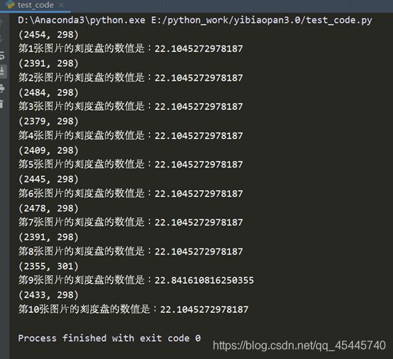 关于精度的问题,要调整画的那个指针的长度,线段的起点,即圆心的位置,指针的粗细等等,都会影响到读数的精度
