九、RISC-V SoC外设——SPI接口 代码讲解
上一篇博文中注释了RISC-V SoC的GPIO外设模块,现在来介绍SPI外设模块。
另外,在最后一个章节中会上传额外添加详细注释的工程代码,完全开源,如有需要可自行下载。
目录
0 RISC-V SoC注解系列文章目录
1. 结构
2. SPI模块
2.1 基础知识
2.2 输入和输出端口
2.3 SPI代码注解
参考:
0 RISC-V SoC注解系列文章目录
零、RISC-V SoC软核笔记详解——前言
一、RISC-V SoC内核注解——取指
二、RISC-V SoC内核注解——译码
三、RISC-V SoC内核注解——执行
四、RISC-V SoC内核注解——除法(试商法)
五、RISC-V SoC内核注解——中断
六、RISC-V SoC内核注解——通用寄存器
七、RISC-V SoC内核注解——总线
八、RISC-V SoC外设注解——GPIO
九、RISC-V SoC外设注解——SPI接口
十、RISC-V SoC外设注解——timer定时器
十一、RISC-V SoC外设注解——UART模块(终篇)
1. 结构
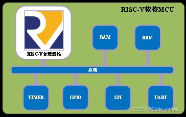
如下图,SPI模块也是通过总线与内核进行交互的。
2. SPI模块
2.1 基础知识
- SPI是串行外设接口(Serial Peripheral Interface)的缩写,是一种高速的,全双工,同步的通信总线。
- SPI通讯协议的优点是支持全双工通信,通讯方式较为简单,且相对数据传输速率较快;缺点是没有指定的流控制,没有应答机制确认数据是否接收。
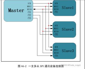
- 一主多从(无论有多少个从设备,都共同使用这3条总线;而每个从设备都有独立的这一条 CS_N 信号线,低电平有效)如下图所示:
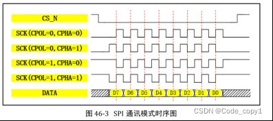
CPOL/CPHA及通讯模式
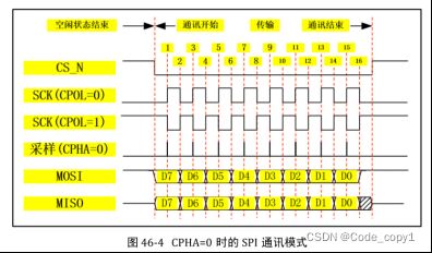
SPI通讯协议一共有四种通讯模式,模式 0、模式 1、模式 2 以及模式 3,这 4 种模式分别由时钟极性(CPOL,Clock Polarity)和时钟相位(CPHA,Clock Phase)来定义,其中CPOL参数规定了空闲状态(CS_N 为高电平,设备未被选中)时SCK时钟信号的电平状态,CPHA规定了数据采样是在 SCK 时钟的奇数边沿还是偶数边沿。
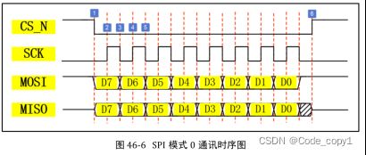
SPI 基本通讯过程
下图表示的是主机视角的通讯时序。SCK、MOSI、CS_N 信号均由主机控制产生,SCK 是时钟信号,用以同步数据,MOSI 是主机输出从机输入信号,主机通过此信号线传输数据给从机,CS_N 为片选信号,用以选定从机设备,低电平有效;而 MISO 的信号由从机产生,主机通过该信号线读取从机的数据。MOSI 与 MISO 的信号只在 CS_N 为低电平的时候才有效,在 SCK 的每个时钟周期 MOSI 和 MISO 传输一位数据。
2.2 输入和输出端口
    input wire clk,
    input wire rst,

    input wire[31:0] data_i,
    input wire[31:0] addr_i,
    input wire we_i,

    output reg[31:0] data_o,//通过总线,将SPI模块中的寄存器数据输出到内核中

//这4个信号,是SPI模块(主)与外设们(从)之间的交互
    output reg spi_mosi,             // spi控制器输出、spi设备输入信号
    input wire spi_miso,             // spi控制器输入、spi设备输出信号
    output wire spi_ss,              // spi设备片选,选择哪一个外设
output reg spi_clk // spi设备时钟,最大频率为输入clk的一半(根据外设来判定时钟频率) 2.3 SPI代码注解
Step1:定义三个寄存器
SPI_CTRL:配置SPI协议的传输模式、使能片选信号;
SPI_DATA:存放主机写入从机和从机返回主机的数据;
SPI_STATUS:标识SPI传输的工作状态(忙或不忙),嵌入式开发中,可通过读该寄存器来判断数据传输是否完成,如果未完成,则不开始下一轮数据传输。
localparam SPI_CTRL   = 4'h0;    // spi_ctrl寄存器地址偏移
localparam SPI_DATA   = 4'h4;    // spi_data寄存器地址偏移
localparam SPI_STATUS = 4'h8;    // spi_status寄存器地址偏移

// spi控制寄存器
// addr: 0x00
// [0]: 1: enable, 0: disable
// [1]: CPOL
// [2]: CPHA
// [3]: select slave, 1: select, 0: deselect 就是SPI的片选信号
// [15:8]: clk div
reg[31:0] spi_ctrl;
// spi数据寄存器
// addr: 0x04
// [7:0] cmd or inout data
reg[31:0] spi_data;
// spi状态寄存器
// addr: 0x08
// [0]: 1: busy, 0: idle
reg[31:0] spi_status; Step2:产生SPI驱动(分频)时钟
写一个计数器clk_cnt来分频,以此产生分频时钟spi_clk;
再写一个计数器spi_clk_edge_cnt,对分频时钟spi_clk的边沿进行计数,以此区分奇数沿和偶数沿,并在数据传输完毕时,将分频时钟spi_clk复位;
// 对输入时钟进行计数
always @ (posedge clk) begin
    if (rst == 1'b0) begin
        clk_cnt <= 9'h0;
    end else if (en == 1'b1) begin
        if (clk_cnt == div_cnt) begin
            clk_cnt <= 9'h0;
        end else begin
            clk_cnt <= clk_cnt + 1'b1;
        end
    end else begin
        clk_cnt <= 9'h0;
    end
end

// 对spi clk沿进行计数
// 每当计数到分频值时产生一个上升沿脉冲
always @ (posedge clk) begin
    if (rst == 1'b0) begin
        spi_clk_edge_cnt <= 5'h0;
        spi_clk_edge_level <= 1'b0;
    end else if (en == 1'b1) begin
        // 计数达到分频值
        if (clk_cnt == div_cnt) begin
            if (spi_clk_edge_cnt == 5'd17) begin
                spi_clk_edge_cnt <= 5'h0;
                spi_clk_edge_level <= 1'b0;
            end else begin
                spi_clk_edge_cnt <= spi_clk_edge_cnt + 1'b1;
                spi_clk_edge_level <= 1'b1;
            end
        end else begin
            spi_clk_edge_level <= 1'b0;
        end
    end else begin
        spi_clk_edge_cnt <= 5'h0;
        spi_clk_edge_level <= 1'b0;
    end
end Step3:利用分频时钟spi_clk的变化沿放置、采样数据。
SPI接口,模式0中,主机只需要负责:
- 在奇数沿采集从机输出的数据(从机采集数据由具体的外设来负责,只需确保主机和从机在同一个协议模式下工作即可);
- 在偶数沿放置写入从机的数据。
对应代码如下:
// bit序列
always @ (posedge clk) begin
    if (rst == 1'b0) begin
        spi_clk <= 1'b0;
        rdata <= 8'h0;
        spi_mosi <= 1'b0;
        bit_index <= 4'h0;
    end else begin
        if (en) begin
            if (spi_clk_edge_level == 1'b1) begin
                case (spi_clk_edge_cnt)
                    // 第奇数个时钟沿
                    1, 3, 5, 7, 9, 11, 13, 15: begin
                        spi_clk <= ~spi_clk;
                        if (spi_ctrl[2] == 1'b1) begin //CPHA == 1;偶数沿采样,奇数沿放数据
                            spi_mosi <= spi_data[bit_index];   // 送出1bit数据 先送高位
                            bit_index <= bit_index - 1'b1;
                        end else begin  //CPHA == 0;奇数沿采样,偶数沿放数据
                            rdata <= {rdata[6:0], spi_miso};   // 读1bit数据
                        end
                    end
                    // 第偶数个时钟沿
                    2, 4, 6, 8, 10, 12, 14, 16: begin
                        spi_clk <= ~spi_clk;
                        if (spi_ctrl[2] == 1'b1) begin  //CPHA == 1;偶数沿采样,奇数沿放数据
                            rdata <= {rdata[6:0], spi_miso};   // 读1bit数据
                        end else begin  //CPHA == 0;奇数沿采样,偶数沿放数据
                            spi_mosi <= spi_data[bit_index];   // 送出1bit数据
                            bit_index <= bit_index - 1'b1;
                        end
                    end
                    17: begin
                        spi_clk <= spi_ctrl[1]; //传送完8bit数据之后 将spi_clk复位
                    end
                endcase
            end
        end else begin
            // 初始状态
            spi_clk <= spi_ctrl[1];
            if (spi_ctrl[2] == 1'b0) begin //CPHA == spi_ctrl[2] == 1'b0 奇数沿采样
                spi_mosi <= spi_data[7];           // 送出最高位数据
                bit_index <= 4'h6;
            end else begin  //spi_ctrl[2] == 1'b1 偶数沿采样
                bit_index <= 4'h7;
            end
        end
    end
end
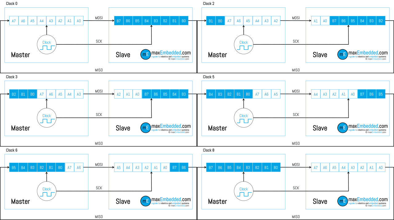
主机数据MOSI写入从机的同时,也会从 从机中读出数据MOSI。
Step4:写SPI外设寄存器
- 根据外设寄存器地址,C语言通过总线写寄存器;
- 更新spi_status寄存器,以表明当前的数据传输状态(是否写完成);
- 发送完成后done == 1'b1,更新数据寄存器spi_data <= {24'h0, rdata};
// write reg
    always @ (posedge clk) begin
        if (rst == 1'b0) begin
            spi_ctrl <= 32'h0;
            spi_data <= 32'h0;
            spi_status <= 32'h0;
        end else begin
            spi_status[0] <= en;
            if (we_i == 1'b1) begin
                case (addr_i[3:0])
                    SPI_CTRL: begin
                        spi_ctrl <= data_i;
                    end
                    SPI_DATA: begin
                        spi_data <= data_i;
                    end
                    default: begin

                    end
                endcase
            end else begin
                spi_ctrl[0] <= 1'b0;
                // 发送完成后更新数据寄存器
                if (done == 1'b1) begin
                    spi_data <= {24'h0, rdata};
                end
            end
        end
end Step5:读SPI外设寄存器
根据外设寄存器地址,嵌入式C语言通过总线读寄存器;
// read reg
always @ (*) begin
    if (rst == 1'b0) begin
        data_o = 32'h0;
    end else begin
        case (addr_i[3:0])
            SPI_CTRL: begin
                data_o = spi_ctrl;
            end
            SPI_DATA: begin
                data_o = spi_data;
            end
            SPI_STATUS: begin
                data_o = spi_status;
            end
            default: begin
                data_o = 32'h0;
            end
        endcase
    end
end 