ti ds90ub953 与ds90ub954 、ds90ub933的调试总结
ti ds90ub953 与ds90ub954 的调试总结
ti的953与954是很好用的进行图像传输的芯片,它们可以通过外部的mode管脚进行模式配置,然后只需要简单的几个寄存器的配置就可以进行图像传输。还可以通过954的iic去配置953的寄存器,甚至通过954的iic去控制953的iic来配置与953相连的sensor的初始化。
以下是调试时参考的ti官网上面的datasheet
http://www.ti.com/lit/ds/symlink/ds90ub953a-q1.pdf
http://www.ti.com/lit/ds/symlink/ds90ub954-q1.pdf
http://www.ti.com/lit/an/snla267a/snla267a.pdf
接下来开始调试:
1:首先配置iic的slave addr 这个是通过外部管脚IDX进行配置的如下图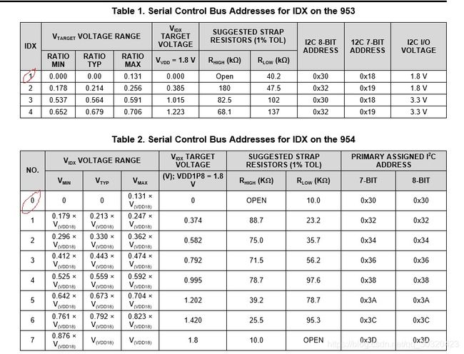
红色框是我的选择地址0x30
2:953 954之间图像进行传输的时候要选择传输模式,两个模式要一致才可以进行传输,模式的选择默认是通过外部管脚mode in进行配置的,但也可以通过设置寄存器来进行选择。模式的选择分为两大类,csi模式和raw模式。953 954在这两个模式下都可以进行图像的传输,同时954的raw模式可以与913,933进行进行传输,953的raw模式是dvp模式她还可以和943, 914进行图像传输。
953模式配置管脚如下图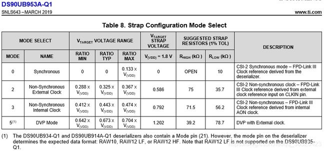
954模式配置管脚如下图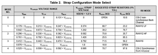
在csi模式下分为同步模式(synchronous)和非同步模式(non synchronous),在non synchronous模式下有分外部时钟输入给953的模式和953内部时钟模式。
在synchronous模式下是954的外部时钟提供给953 954工作使用。对于mode 管脚的配置953如上图的table 8选择 mode 0,对于954如上图table 2 选择 mode 4。时钟的提供如下图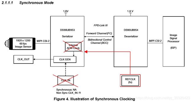
在non synchronous 模式下是953的外部时钟或者内部产生时钟提供给954使用。对于mode管脚的配置,953如上图的table 8选择mode2,使用外部时钟,选择mode 3,内部时钟。对于954如上图的table 2 选择mode 0.
使用外部时钟如下图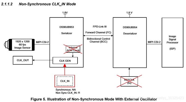
使用内部时钟如下图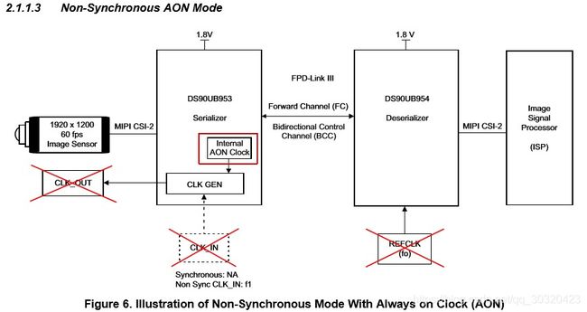
在raw模式下我选择的是raw10模式,953mode管脚配置为上图table 8的mode 5,954mode管脚配置为上图table 2的mode 3. 953配置为dvp模式时必须使用外部时钟,并且外部时钟必须与 csi输入数据同步。这里我给953的时钟频率与csi输入的数据pix clk一致。
3: 对于寄存器的配置
对于954的寄存器配置在不同模式下都是一样的如下:
iic_writeByte(ds90ub954_addr, 0x4c, 0x01);
iic_writeByte(ds90ub954_addr, 0x32, 0x01);
iic_writeByte(ds90ub954_addr, 0x33, 0x33);
iic_writeByte(ds90ub954_addr, 0x20, 0x20);
输出模式配置为1 lane 持续时钟模式
对于953的寄存器配置在csi 模式下如下:
iic_writeByte(ds90ub953_addr, 0x02, 0x03);
输入为1 lane模式,默认的是4 lane csi模式
对于953的寄存器配置在dvp模式下如下:
iic_writeByte(ds90ub953_addr, 0x02, 0x03);
iic_writeByte(ds90ub953_addr, 0x03, 0x15);//该寄存器可以配置953的输出模式
iic_writeByte(ds90ub953_addr, 0x04, 0x05);//该寄存器配置dvp的模式,raw10
iic_writeByte(ds90ub953_addr, 0x05, 0x1b);//dvp模式下,clk_div 必须为 1
iic_writeByte(ds90ub953_addr, 0x10, 0x18);
iic_writeByte(ds90ub953_addr, 0x11, 0x2b);
4:调试过程中的一些确认方式。
首先是要确保953 954两块芯片link上了,也就是 954的pass 管脚和lock管脚输出高电平。
如果link上了,读取954的0x5b寄存器的值应该是953的slave addr的值。
可以读取954的 0x73 0x74 line count 寄存器和0x75 0x76 line len寄存器来确认接收到的数据的大小是否与953发送过来的是否一致。
在调试过程中在csi synchronous模式下调通了,但是后面增加了953 954之间连线的长度后,953 954又link不上了,后面改为了non-synchoronous模式后又可以了。不知道为什么会出现这样的现象,初步怀疑是两种模式的时钟频率的原因。
调试时953是与fpga连接的,所以没有设置sensor的初始化部分
5:在调试ds90ub925 ,ds90ub926的时候,只需要外部配置管脚配置好后,不需要对925 926进行初始化就可以进行数据的传输
以上部分照搬作者:https://blog.csdn.net/qq_30320423/article/details/101159808十分感谢
ds90ub954、ds90ub953,ds90ub923补充:
1.ds90ub954、ds90ub953都有内部图形生成器,可直接输出自定义颜色的图像。
2.ds90ub954支持dvp模式可以传输10bit和12bit的数据。可直接和ds90ub933对接,目前调试的时候发现不需要设置ds90ub933的寄存器,我的理解是ds90ub954设置好了会反馈到ds90ub933进行配置,配置的寄存器基于上面的修改了954dvp模式选择raw10,
设置数据高低8位,修改了输出的数据类型为0x1e-yuv422,修改了954 fv lv的输入极性,目前933输入接入了行场信号,看手册好像说可以不需要(欢迎指导)。
3.ds90ub954、ds90ub953貌似也可以支持dvp模式。但是我们在调试的时候没有调通(可能当时我没太搞懂造成的,没有设置对fv lv的极性,高低8位953没看到哪里可以设置,感觉按照现在的配置应该也可以接入(欢迎指导交流))。
附1:926 输出默认图像
i2c_write 0x02 0x58 0x66 0x03
i2c_write 0x02 0x58 0x67 0x06
i2c_write 0x02 0x58 0x66 0x07
i2c_write 0x02 0x58 0x67 0x20
i2c_write 0x02 0x58 0x66 0x08
i2c_write 0x02 0x58 0x67 0x03
i2c_write 0x02 0x58 0x66 0x09
i2c_write 0x02 0x58 0x67 0x1e
i2c_write 0x02 0x58 0x66 0x04
i2c_write 0x02 0x58 0x67 0x98
i2c_write 0x02 0x58 0x66 0x05
i2c_write 0x02 0x58 0x67 0xd4
i2c_write 0x02 0x58 0x66 0x06
i2c_write 0x02 0x58 0x67 0x20
i2c_write 0x02 0x58 0x66 0x0c
i2c_write 0x02 0x58 0x67 0xd8
i2c_write 0x02 0x58 0x66 0x0d
i2c_write 0x02 0x58 0x67 0x23
i2c_write 0x02 0x58 0x66 0x0a
i2c_write 0x02 0x58 0x67 0x0a
i2c_write 0x02 0x58 0x66 0x0b
i2c_write 0x02 0x58 0x67 0x02
i2c_write 0x02 0x58 0x66 0x0e
i2c_write 0x02 0x58 0x67 0x03
i2c_write 0x02 0x58 0x65 0x03
i2c_write 0x02 0x58 0x39 0x02
i2c_write 0x02 0x58 0x64 0x11
附1:953 输出默认图像
IN=$1
#board.devAddr = 0x30
# # CSI sel and CSI enable
# i2c_write 0x02 0x30 0x32 0x01
# time.sleep(0.5
# i2c_write 0x02 0x30 0x33 0x01
# time.sleep(0.5
# enable pat gen
#i2c_write 0x02 0x30
i2c_write 0x02 0x30 0xB0 0x00
i2c_write 0x02 0x30 0xB1 0x01
i2c_write 0x02 0x30 0xB2 $IN #enable pattern generator
i2c_write 0x02 0x30 0xB1 0x02
i2c_write 0x02 0x30 0xB2 0x37 #fixed color pattern 8 color bars block size of 5
i2c_write 0x02 0x30 0xB1 0x03
i2c_write 0x02 0x30 0xB2 0x1e #CSI Data Identifier (0x24 = RGB888 0x2C = RAW12 0x2B = RAW10)
i2c_write 0x02 0x30 0xB1 0x04
i2c_write 0x02 0x30 0xB2 0x16 #line size (15:8)
i2c_write 0x02 0x30 0xB1 0x05
i2c_write 0x02 0x30 0xB2 0x80 #line size (7:0)
i2c_write 0x02 0x30 0xB1 0x06
i2c_write 0x02 0x30 0xB2 0x02 #bar size (15:8)
i2c_write 0x02 0x30 0xB1 0x07
i2c_write 0x02 0x30 0xB2 0xd0 #bar size (7:0)
i2c_write 0x02 0x30 0xB1 0x08
i2c_write 0x02 0x30 0xB2 0x02 #active lines per frame (15:8)
i2c_write 0x02 0x30 0xB1 0x09
i2c_write 0x02 0x30 0xB2 0xd0 #active lines per frame (7:0)
i2c_write 0x02 0x30 0xB1 0x0a
i2c_write 0x02 0x30 0xB2 0x04 #total lines per frame (15:8)
i2c_write 0x02 0x30 0xB1 0x0b
i2c_write 0x02 0x30 0xB2 0x1a #total lines per frame (7:0)
i2c_write 0x02 0x30 0xB1 0x0c
i2c_write 0x02 0x30 0xB2 0x0c #line period (15:8)
i2c_write 0x02 0x30 0xB1 0x0d
i2c_write 0x02 0x30 0xB2 0x67 #line period (7:0)
i2c_write 0x02 0x30 0xB1 0x0e
i2c_write 0x02 0x30 0xB2 0x21 #vertical back porch
i2c_write 0x02 0x30 0xB1 0x0f
i2c_write 0x02 0x30 0xB2 0x0a #vertical front porch
#
i2c_write 0x02 0x30 0xB1 0x10
i2c_write 0x02 0x30 0xB2 0x11 #1st byte of fixed color
i2c_write 0x02 0x30 0xB1 0x11
i2c_write 0x02 0x30 0xB2 0x22 #2nd byte of fixed color
i2c_write 0x02 0x30 0xB1 0x12
i2c_write 0x02 0x30 0xB2 0x33 #3rd byte of fixed color
i2c_write 0x02 0x30 0xB1 0x13
i2c_write 0x02 0x30 0xB2 0x44 #4th byte of fixed color
i2c_write 0x02 0x30 0xB1 0x14
i2c_write 0x02 0x30 0xB2 0x55 #5th byte of fixed color
i2c_write 0x02 0x30 0xB1 0x15
i2c_write 0x02 0x30 0xB2 0x66 #6th byte of fixed color
i2c_write 0x02 0x30 0xB1 0x16
i2c_write 0x02 0x30 0xB2 0x77 #7th byte of fixed color
i2c_write 0x02 0x30 0xB1 0x17
i2c_write 0x02 0x30 0xB2 0x88 #8th byte of fixed color
i2c_write 0x02 0x30 0xB1 0x18
i2c_write 0x02 0x30 0xB2 0x88 #9th byte of fixed color
i2c_write 0x02 0x30 0xB1 0x19
i2c_write 0x02 0x30 0xB2 0x99 #10th byte of fixed color
i2c_write 0x02 0x30 0xB1 0x1A
i2c_write 0x02 0x30 0xB2 0xaa #11th byte of fixed color
i2c_write 0x02 0x30 0xB1 0x1B
i2c_write 0x02 0x30 0xB1 0xbb #12th byte of fixed color
i2c_write 0x02 0x30 0xB1 0x1C
i2c_write 0x02 0x30 0xB2 0xcc #13th byte of fixed color
i2c_write 0x02 0x30 0xB1 0x1D
i2c_write 0x02 0x30 0xB2 0xdd #14th byte of fixed color
i2c_write 0x02 0x30 0xB1 0x1E
i2c_write 0x02 0x30 0xB2 0xee #15th byte of fixed color
i2c_write 0x02 0x30 0xB1 0x1F
i2c_write 0x02 0x30 0xB2 0xff #16th byte of fixed color
以上为个人的理解与调试总结,如有错误欢迎指正。