【论文阅读】Multi-Modal Fusion Transformer for End-to-End Autonomous Driving
-
参考与前言 resource
代码:https://github.com/autonomousvision/transfuser
作者自己的博客:https://autonomousvision.github.io/transfuser/
论文地址:http://www.cvlibs.net/publications/Prakash2021CVPR.pdf
博客园外链(因为那边没广告&主题比较优美 hhhh):https://www.cnblogs.com/kin-zhang/articles/15685464.html
1. Motivation
问题场景
主要是因为受限相机和激光雷达的各自缺点而出的这个文章 → 真的和当时自身想法的改进贴想的是一样的… 但是能力有限我做不出来 lol
这是一个要解决的问题:

在这里,相机可能看得到交通灯,激光雷达可以看到红色区域的车,所以在将两者结合后 自身就知道不应该在此时立刻右转。也就是对自身的整个3D场景进行建模
问题 → 贡献
- 怎样把多传感器之间的信息做结合
- 但是基于1的基础上,他们又可以有自己的独立运行感知
- 怎样的融合手段能达到最好的效果
Contribution
证明:现有的融合方式并不能解决提出的问题场景,十字路口无保护转弯/鬼探头
提出:TransFuser 解决上面提到的三个问题 —— 结合,又不丧失各自的独立运行,得到好的效果 → incorporate the global context of the 3D scene into the feature extraction layers of different modalities

-
我寻思着鬼探头他们也没解决吧 毕竟鬼探头 LiDAR&相机 也看不到
-
这个different modalities emmm 没看懂是个啥,能通俗点理解成 构建了一下车身周围的3D信息而不缺失吗…
- 感觉好像也不对,因为车身周围的信息LiDAR就能构建,应该是不止物体信息 还有其他的信息 比如红绿灯、停车线等等等
modalities是指不同的传感器
用sensor不好嘛 emmm我知道为什么了:多模态的概念,不同的数据输入
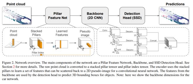
2. Method
整体网络框架:

- 融合传感器的 Multi-Model Fusion Transformaer
- auto-regressive waypoint prediction network
- 应该说的是右下角那块?
2.1 输入
LiDAR PointCloud
将点云转成2-bin柱状图 (然后偷摸去查了一下他们的 reference 45 PRECOG: PREdiction Conditioned On Goals in Visual Multi-Agent Settings 十分眼熟)
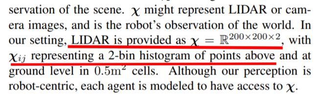
reference 45的截图 (200x200x2)但实际此文中是256x256x2
-
看懂了,不是200x200 而是人为给了 z轴高度为2米,2米以下压一层,2米以上压一层,压一层后直接统计对应区间内的点云个数,做一个最大值的平均操作使得数据都是<1的,最后把这两层和在一起256x256x2 → 此点可有进步
这个完全就直接200x200了啊 从代码里看的话def lidar_to_histogram_features(lidar, crop=256): """ Convert LiDAR point cloud into 2-bin histogram over 256x256 grid """ def splat_points(point_cloud): # 256 x 256 grid pixels_per_meter = 8 hist_max_per_pixel = 5 x_meters_max = 16 y_meters_max = 32 xbins = np.linspace(-2*x_meters_max, 2*x_meters_max+1, 2*x_meters_max*pixels_per_meter+1) ybins = np.linspace(-y_meters_max, 0, y_meters_max*pixels_per_meter+1) hist = np.histogramdd(point_cloud[...,:2], bins=(xbins, ybins))[0] hist[hist>hist_max_per_pixel] = hist_max_per_pixel overhead_splat = hist/hist_max_per_pixel return overhead_splat below = lidar[lidar[...,2]<=2] above = lidar[lidar[...,2]>2] below_features = splat_points(below) above_features = splat_points(above) features = np.stack([below_features, above_features], axis=-1) features = np.transpose(features, (2, 0, 1)).astype(np.float32) return features温馨提示:numpy.histogramdd
-
below = lidar[lidar[...,2]<=2]这一步压完之后就是2D了,这样不会丧失几何信息吗?恒哥:嗯嗯,确实没几何信息了;这样处理只有统计信息
工程上 pillows maxpooling中这步也有信息损失 [信息损失就是在这里发生的]:
-
车辆前方32m,左右16m 范围点云加入考虑,然后就是一个32x32m的了,以0.125作为分辨率,那么整个像素值为256x256了

此文原文
- 咦 竟然没有车后的点云哎 奇怪了 不需要吗?
相机 RGB
FOV:100度,收到的RGB是400x300的,然后转成256x256的
震惊的是:只用了一个相机哎!想想lbc, wor哪个不是前向环绕一圈 180度的 hhh
2.2 输出
输出直接在BEV鸟瞰空间中,以自身车为中心,一系列时间内的路径点 { w t = ( x t , y t ) } t = 1 T \left\{\mathbf{w}_{t}=\left(x_{t}, y_{t}\right)\right\}_{t=1}^{T} {wt=(xt,yt)}t=1T;文中使用的是T=4
-
论文详情

2.3 框架
-
为什么这两者的融合不能直接拿外参进行标定 外参标后不就可以对应到了两者的空间位置嘛?
是因为必须要选一个作为主视角训练吗,RGB不够多吗? 几何距离信息也缺失 -
原来作者的博客里也写了这种外参投影的方式,并说明了 缺点:due to the lack of global context since features are aggregated from a local region in the projected 2D or 3D space.
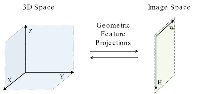
先前关于传感器融合的工作主要集中在相机和 LiDAR 传感器之间基于几何的融合。 在这种方法中,3D 空间(激光雷达点云)中的点被投影到图像空间(相机输入)中的像素,并从投影位置聚合信息。 特别是,将与这些投影位置对应的特征(使用卷积神经网络提取)组合在一起。 这在上图中称为几何特征投影。 这已被证明在视觉任务上非常有效,例如物体检测、运动预测和深度估计,但尚未在端到端驾驶的背景下进行广泛探索。

在上图中,对于图像中的交通灯区域(以黄色显示),几何融合聚合了 LiDAR 点云中蓝色区域的特征,因为这些点投影到图像空间中的黄色区域。 然而,为了安全地在十字路口导航,必须从 LiDAR 点云中的红色区域聚合特征,因为它与从左向右移动的车辆重叠。
-
但是 但是 如果以点云为主不就行了? 这一点好奇怪啊,明明点云信息有那一部分,难道是说作者完全只是把点云投到图片上,图片以外的点云直接去掉了?
-
woc 还真是,直接把图片以外的点云卡掉来说明这个不行 这也太。。。
# 相机的配置
pixels_per_world = 8
w = 400
h = 300
fov = 100
F = w / (2 * np.tan(fov * np.pi / 360))
fy = F
fx = 1.1 * F
cam_height = 2.3

start_x = w // 2 - crop // 2
start_y = h // 2 - crop // 2
end_x = start_x + crop
end_y = start_y + crop

for i in range(lidar.shape[0]):
		# 相机尺寸外的点都不要了 只有在里面的 才进if
    if result[i][0] >= start_x and result[i][0] < end_x and result[i][1] >= start_y and result[i][1] < end_y:
        result[i][0] -= start_x
        result[i][1] -= start_y
        valid_lidar_points.append(lidar[i])
        valid_cam_points.append([int(result[i][0]), int(result[i][1])])
        bev_x = min(int((lidar[i][0] + 16) * pixels_per_world), crop-1)
        bev_y = min(int(lidar[i][1] * pixels_per_world), crop-1)
        valid_bev_points.append([bev_x, bev_y])
-
-
所以才提出了这样一种网络框架:
放大看图
Transformer
key idea主要是来源于:Attention is all you need 一文;本文每个层之间的 Transformer takes as input a sequence consisting of discrete tokens, each represented by a feature vector. The feature vector is supplemented by a positional encoding to incorporate positional inductive biases
总的来说就是 emmm 我用了这个attention的机制,然后主要是把双传感器信息进行 a positional encoding 得到 fecture vector
-
这里positional encoding是个啥 外参?
好的 我知道了 是因为需要前提知识,首先是positional encoding并不是我想的那种外参的positional 而是降维后的序列位置,详情可见此youtube链接解释 positional embading

其中的 M q ∈ R D f × D q , M k ∈ R D f × D k , M v ∈ R D f × D v \mathbf{M}^{q} \in \mathbb{R}^{D_{f} \times D_{q}}, \mathbf{M}^{k} \in \mathbb{R}^{D_{f} \times D_{k}},\mathbf{M}^{v} \in \mathbb{R}^{D_{f} \times D_{v}} Mq∈RDf×Dq,Mk∈RDf×Dk,Mv∈RDf×Dv 都是权重矩阵
attention weight由 Q , K \mathbf Q, \mathbf K Q,K 点积后给到 each query
A = softmax ( Q K T D k ) V (3) \mathbf{A}=\operatorname{softmax}\left(\frac{\mathbf{Q K}^{T}}{\sqrt{D_{k}}}\right) \mathbf{V} \tag{3} A=softmax(DkQKT)V(3)
-
上面这波对应代码:(好像都是一个套路 这些公式也都是来源 Attention is all you need 一文)
class SelfAttention(nn.Module):
    """
    A vanilla multi-head masked self-attention layer with a projection at the end.
    """

    def __init__(self, n_embd, n_head, attn_pdrop, resid_pdrop):
        super().__init__()
        assert n_embd % n_head == 0
        # key, query, value projections for all heads
        self.key = nn.Linear(n_embd, n_embd)
        self.query = nn.Linear(n_embd, n_embd)
        self.value = nn.Linear(n_embd, n_embd)
        # regularization
        self.attn_drop = nn.Dropout(attn_pdrop)
        self.resid_drop = nn.Dropout(resid_pdrop)
        # output projection
        self.proj = nn.Linear(n_embd, n_embd)
        self.n_head = n_head

    def forward(self, x):
        B, T, C = x.size()

        # calculate query, key, values for all heads in batch and move head forward to be the batch dim
        k = self.key(x).view(B, T, self.n_head, C // self.n_head).transpose(1, 2) # (B, nh, T, hs)
        q = self.query(x).view(B, T, self.n_head, C // self.n_head).transpose(1, 2) # (B, nh, T, hs)
        v = self.value(x).view(B, T, self.n_head, C // self.n_head).transpose(1, 2) # (B, nh, T, hs)

        # self-attend: (B, nh, T, hs) x (B, nh, hs, T) -> (B, nh, T, T)
        att = (q @ k.transpose(-2, -1)) * (1.0 / math.sqrt(k.size(-1)))
        att = F.softmax(att, dim=-1)
        att = self.attn_drop(att)
        y = att @ v # (B, nh, T, T) x (B, nh, T, hs) -> (B, nh, T, hs)
        y = y.transpose(1, 2).contiguous().view(B, T, C) # re-assemble all head outputs side by side

        # output projection
        y = self.resid_drop(self.proj(y))
        return y
最后 transformer 使用非线性的 transformation 去计算输出 features,所以 out 和 in 是同样的大小 shape
F out = MLP ( A ) + F in (4) \mathbf{F}^{\text {out }}=\operatorname{MLP}(\mathbf{A})+\mathbf{F}^{\text {in }} \tag{4} Fout =MLP(A)+Fin (4)
-
December 12, 2021 8:20 PM 等我去套娃 搞清楚transformers to image的东西
代码中的GPT可以参照这个教程,论文中的
Transformer论文逐段精读【论文精读】_哔哩哔哩_bilibili
ViT论文逐段精读【论文精读】_哔哩哔哩_bilibili
与 NLP 中的 token input 结构不同,我们对 gird structed feature map 进行操作。 与先前将 transformer 应用于图像的工作类似 [52, 10, 43, 20],我们将每个传感器的中间 feature map 视为一个集合而不是空间网格,并将集合的每个元素视为一个token。 图像和 LiDAR BEV 输入的卷积特征提取器在不同层对场景的不同方面进行编码。 因此,我们在整个编码器中以 multiple scales 来融合这些feature
每个传感器的feature map都会弄成一个3D tensor: H × W × C H \times W \times C H×W×C,所以对于 S S S 个不同的传感器信息,这些 feature 在一起成为一个长度为 ( S ∗ H ∗ W ) × C (S*H*W)\times C (S∗H∗W)×C 的序列,这样一来网络在训练时就可以推断不同的tokens的 spatial dependencies
使用 Linear 把当前速度也作为输入到维度 C 上的向量,在embeddings的时候加上去
self.vel_emb = nn.Linear(1, n_embd)
velocity_embeddings = self.vel_emb(velocity.unsqueeze(1)) # (B, C)
# add (learnable) positional embedding and velocity embedding for all tokens
x = self.drop(self.pos_emb + token_embeddings + velocity_embeddings.unsqueeze(1)) # (B, an * T, C)
简单总结一下:
- 尺寸输入:LiDAR 256x256x2 图片 256x256x3
- 经过conv + pool后得到的是64x64x64送到transformer进行编码,实际的方式也比较粗暴 处理后 直接emding全部相加走transformer
- 出来的尺寸还是一样的(其实不是一样的是输出之后做了一次x倍插值 interpolate)
然后直接加到了原数据上面
一直顺下去,就像框架图所示那样一共有4层,例如一个:
# fusion at (B, 64, 64, 64)
image_embd_layer1 = self.avgpool(image_features)
lidar_embd_layer1 = self.avgpool(lidar_features)
image_features_layer1, lidar_features_layer1 = self.transformer1(image_embd_layer1, lidar_embd_layer1, velocity)
image_features_layer1 = F.interpolate(image_features_layer1, scale_factor=8, mode='bilinear')
lidar_features_layer1 = F.interpolate(lidar_features_layer1, scale_factor=8, mode='bilinear')
image_features = image_features + image_features_layer1
lidar_features = lidar_features + lidar_features_layer1
Resnet Conv
这一块好像没啥说的,因为直接用的pytorch里面有的结构,不过image加载了预训练的权重
# image
self.features = models.resnet34(pretrained=True)

# LiDAR
self._model = models.resnet18()

# predict
pred_wp = model(fronts+lefts+rights+rears, lidars, target_point, gt_velocity)
然后把最后一层的fc全连接层去掉了,取而代之的是再外面联合的时候做了一层join,也就是框架图里的
# (avgpool): AdaptiveAvgPool2d(output_size=(1, 1)) 是两个resnet的输出地方
self.join = nn.Sequential(nn.Linear(512, 256), nn.ReLU(inplace=True), nn.Linear(256, 128), nn.ReLU(inplace=True), nn.Linear(128, 64), nn.ReLU(inplace=True), ).to(self.device)
# 最后输出的时候再用 decoder 从join 那边收到input_size=target,hidden_size=feature
# 然后输出output一个线性层
self.decoder = nn.GRUCell(input_size=2, hidden_size=64).to(self.device)
self.output = nn.Linear(64, 2).to(self.device)
3. Conclusion
其实实验部分也可以看看 以carla leaderboard提出的指标来对比的,值得一提的是做了ablation study 消融实验(俗称控制变量法)来证明multi-scale fusion、attention layers、positional embedding都是必要的
结论部分主要是 总结一下:我证明了现有的传感器融合方法来的模仿学习存在比较高的违规率(撞人 闯红灯啥的),我们提出了一种 Multi-Modal transfuser
Future work:基于我们的model flexible and generic,所以探索探索其他更多传感器融入应该也是很不错的,比如radar啥的
后话:这篇文章感觉网络介绍的很清晰,代码也基本对着一目了然 比wor代码轻量不少,后续应该会尝试跑一下