本篇解读2021CVPR旋转目标检测论文:ReDet:A Rotation-equivariant Detector for Aerial Object Detection。附上地址和源码链接:
论文下载地址
源码地址
这是本人组会上做的ppt。简单说创新点有两个:
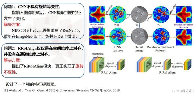
1)利用NIPS2019的e2cnn思想重写了ResNet50并命名为ReCNN,使得CNN具有旋转等变性。即当输入图像发生旋转时,CNN提取到的特征一样。
2)在经过e2cnn提取到图像的特征向量F(K*N,H,W)后,在通道维度上,可以理解为划分成N个组(N=4/8)代表4个方向或8个方向,而每组的子通道数为K。但RRoIAlign模块仅仅是对于不同朝向的物体在空间维度上进行了校正,但在通道维度上并不对齐,故作者设计了RiROIAlign模块在通道维度上和空间维度上均进行了对齐,从而得到了旋转不变性的特征。
总的来说:本文就是设计了一个非常强的特征提取器。
这块我也不理解,e2cnn太硬核了。只是说下:作者在写好ReCNN后,在ImageNet上重新训练并在测试数据集上微调。(羡慕有能力训练Backbone的人)。
在模型结构图中的意思是首先使用RRoiAlign模块进行了空间对齐,之后在循环交换各个通道,比如r=2,将Cn2通道值赋给Cn1,Cn1的值赋给Cnn…并在前后两个通道间执行双线性插值来计算当前通道像素值。(我在这里比较懵逼,所以去看了看源码)。源码位置:ReDet-master\mmdet\ops\riroi_align\src\riroi_align_kernel.cu。我尽量做到详细注释。不懂欢迎评论交流。
#include
#include
#include
#define PI 3.141592653
//CUDA是并行计算,即多线程计算。每个线程对应池化后一个ROI的一个像素点的计算。
//i代表为每个线程的id,n代表CUDA当前分配的总的线程数。
#define CUDA_1D_KERNEL_LOOP(i, n) \
for (int i = blockIdx.x * blockDim.x + threadIdx.x; i < n; \
i += blockDim.x * gridDim.x)
//块大小为1024.
#define THREADS_PER_BLOCK 1024
//根据块大小得到网格大小。
inline int GET_BLOCKS(const int N) {
int optimal_block_num = (N + THREADS_PER_BLOCK - 1) / THREADS_PER_BLOCK;
int max_block_num = 65000;
return min(optimal_block_num, max_block_num);
}
//双线性插值部分不贴了,网上注释挺多的。
template <typename scalar_t>
__device__ scalar_t bilinear_interpolate(const scalar_t *bottom_data,
const int height, const int width,
scalar_t y, scalar_t x)
/
}
template <typename scalar_t>
__global__ void RiROIAlignForward(const int nthreads, const scalar_t *bottom_data,
const scalar_t *bottom_rois,
const scalar_t spatial_scale,
const int sample_num, const int channels,
const int height, const int width,
const int pooled_height, const int pooled_width,
const int nOrientation,
scalar_t *top_data)
//介绍下各个参数的含义:
//*bottom_data: 是输入特征向量图(K,N,H,W)的展成一维数组后的指针。
//*bottom_rois:就是RPN建议出来的rois(cx,cy,w,h,theta)的一维数组指针;
//nOrientation: 代表将通道划分成4/8组
//*top_data:池化后特征图的指针。
// index:就是当前线程id,即池化后*top_data所对应的下标。
CUDA_1D_KERNEL_LOOP(index, nthreads) {
// (n, c, ph, pw) is an element in the pooled output
// 由于index是一维数组,为了计算方便,计算出一维数组对应的输出特征图的位置(n,c,o,ph,pw):即当前
//index对应第n张图像的第o组通道上的(ph,pw)位置。
int pw = index % pooled_width;
int ph = (index / pooled_width) % pooled_height;
int o = (index / pooled_width / pooled_height) % nOrientation;
int c = (index / pooled_width / pooled_height / nOrientation) % channels;
int n = index / pooled_width / pooled_height / nOrientation / channels;
// 取出roi框的下标。
const scalar_t* offset_bottom_rois = bottom_rois + n * 6;
int roi_batch_ind = offset_bottom_rois[0];
// 得到roi的(cx,cy,w,h,theta)
scalar_t roi_center_w = offset_bottom_rois[1] * spatial_scale;
scalar_t roi_center_h = offset_bottom_rois[2] * spatial_scale;
scalar_t roi_width = offset_bottom_rois[3] * spatial_scale;
scalar_t roi_height = offset_bottom_rois[4] * spatial_scale;
scalar_t theta = offset_bottom_rois[5];
// 得到roi的宽和高
roi_width = max(roi_width, (scalar_t)1.);
roi_height = max(roi_height, (scalar_t)1.);
// 得到在h方向需要插值的点的个数,比如池化为7*7大小:则77/7=10就是每个子块高为10; w方向同理。
scalar_t bin_size_h = static_cast<scalar_t>(roi_height) / static_cast<scalar_t>(pooled_height);
scalar_t bin_size_w = static_cast<scalar_t>(roi_width) / static_cast<scalar_t>(pooled_width);
// 对应论文 r = theta*N/(2*pi)公式,即得到当前roi在哪组通道
scalar_t ind_float = theta * nOrientation / (2 * PI);
// 将ind_float取整
int ind = floor(ind_float);
// 得到论文中公式9中的系数alpha值。
scalar_t l_var = ind_float - (scalar_t)ind;
scalar_t r_var = 1.0 - l_var;
// 得到ind开始旋转通道值(就是排除theta>2*pi情况。超出一圈取余数):
ind = (ind + nOrientation) % nOrientation;
// 得到需要调整通道的index。
// 比如 ind = 0, o = 0,则ind=0.此时 ind_rot = 0; ind_rot_plus = 1;
==含义就是 ind = 0朝向的物体 对于0号输出通道的计算需要 借助输入特征向量的0和1号通道的像素值。==
int ind_rot = (o - ind + nOrientation) % nOrientation;
int ind_rot_plus = (ind_rot + 1 + nOrientation) % nOrientation;
// 取出ind_rot和ind_rot_plus所对应像素值
const scalar_t* offset_bottom_data =
bottom_data + (roi_batch_ind * channels * nOrientation + c * nOrientation + ind_rot) * height * width;
const scalar_t* offset_bottom_data_plus =
bottom_data + (roi_batch_ind * channels * nOrientation + c * nOrientation + ind_rot_plus) * height * width;
// 双线性插值采样的数目,通常为2
int roi_bin_grid_h = (sample_num > 0)
? sample_num
: ceil(roi_height / pooled_height); // e.g., = 2
int roi_bin_grid_w =
(sample_num > 0) ? sample_num : ceil(roi_width / pooled_width);
// 将roi变成[xmin,ymin,theta]格式
scalar_t roi_start_h = -roi_height / 2.0;
scalar_t roi_start_w = -roi_width / 2.0;
scalar_t cosscalar_theta = cos(theta);
scalar_t sinscalar_theta = sin(theta);
// 确定采样点总数,最终取均值。
const scalar_t count = roi_bin_grid_h * roi_bin_grid_w; // e.g. = 4
scalar_t output_val = 0.;
// 循环遍历每个子块内的像素值,比如roi_w = 77, roi_h = 777, pooled_w=pooed_h=7.
//则每个子块为(77/7, 777/7)大小,即下面代码表示遍历每个子块内像素值的位置。
for (int iy = 0; iy < roi_bin_grid_h; iy++) { // e.g., iy = 0, 1
const scalar_t yy = roi_start_h + ph * bin_size_h +
static_cast<scalar_t>(iy + .5f) * bin_size_h /
static_cast<scalar_t>(roi_bin_grid_h); // e.g., 0.5, 1.5
for (int ix = 0; ix < roi_bin_grid_w; ix++) {
const scalar_t xx = roi_start_w + pw * bin_size_w +
static_cast<scalar_t>(ix + .5f) * bin_size_w /
static_cast<scalar_t>(roi_bin_grid_w);
// 将每个位置执行放射变换,得到旋转后位置
scalar_t x = xx * cosscalar_theta - yy * sinscalar_theta + roi_center_w;
scalar_t y = xx * sinscalar_theta + yy * cosscalar_theta + roi_center_h;
// 有了旋转位置(y,x)后,执行双线性插值得到 当前组通道的位置的像素值。
scalar_t val = bilinear_interpolate<scalar_t>(
offset_bottom_data, height, width, y, x);
scalar_t val_plus = bilinear_interpolate<scalar_t>(
offset_bottom_data_plus, height, width, y, x);
// 执行论文公式9中双线性插值。
output_val += r_var * val + l_var * val_plus;
}
}
// 取均值
output_val /= count;
// 将值放到对应输出特征图中index的像素值。
top_data[index] = output_val;
}
}
从代码可看出,并不是作者论文中所说的先 空间对齐在通道对齐。 作者在实现上将二者结合起来,即确定通道位置的像素值之后顺便执行了RRoIAlign。
如果还是觉得蒙,我这里给出一个示例,自己手推了一下运行过程。也是ppt。
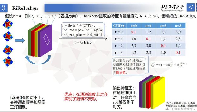
假设N=4,即划分成4组通道,对应代码中的nOrientation。r即ind,o代表池化后特征向量的通道下标。以表格为例,当r=1时,o=1时候,即将输入通道的0和1号通道像素值拿去做RiRoiAlign,并将计算得到像素值放到o=1号位置,即实现了通道对齐。就是循环编码过程。
感觉RiRoiAlign本质上是让不同朝向的物体在通道维度上放到了一个相对的参考系下,让不同朝向的物体从自身角度看,通道位置和自身朝向始终对齐。从而实现了真正意义上旋转不变性。若有问题欢迎+vx:wulele2541612007,拉你进群探讨交流。