ADI Blackfin DSP处理器-BF533的开发详解15:RS232串口的实现(含源代码)
硬件准备
ADSP-EDU-BF533:BF533开发板
AD-HP530ICE:ADI DSP仿真器
软件准备
Visual DSP++软件
硬件链接
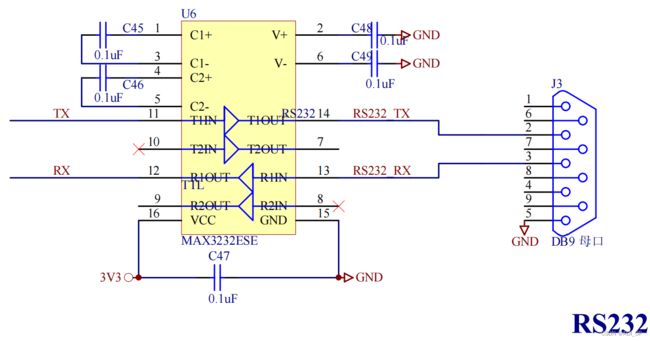
硬件设计原理图
实现原理
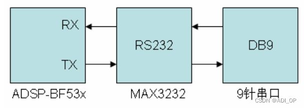
ADSP-EDU-BF533 开发板上设计了一个 RS232 接口,该接口通过 ADSP-BF53x 上的 UART 接口,扩展 RS232协议的芯片实现。通过串口延长线连接计算机可实现串口通讯功能。
UART 接口的通讯波特率是通过系统时钟分频实现的,系统时钟是通过输入晶振频率通过 PLL 后实现的,板卡上采用的晶振频率为 25MHz,具体波特率配置可以参考之前的 UART 接口介绍。
硬件连接示意图
代码实现功能
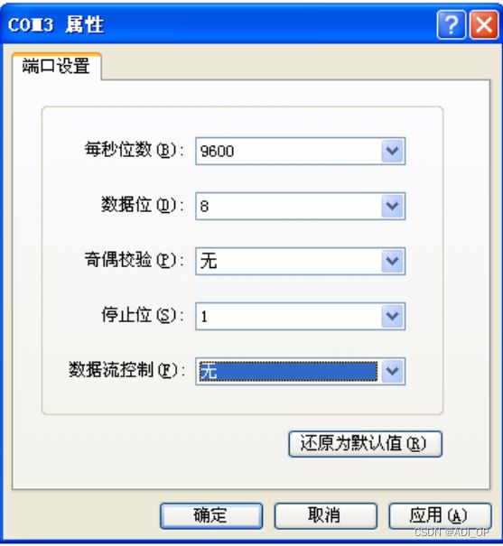
代码实现了 UART 接口的自动波特率检测功能,运行 Windows 上自带的超级中断软件,其路径在:“开始”菜单 ->所有程序->附件->通讯->超级终端。将超级终端设置的波特率为 9600。编译并运行 VisualDSP++ 5.0 工程文件
BF53x_RS232.dpj 的代码,打开超级中断窗口,通过计算机键盘输入”@”,这时板卡会自动识别当前超级终端通讯的波特率,与当前超级终端建立连接,并将超级中断发送的键值返回打印在超级终端窗口上。
测试步骤
1. 将仿真器(ICE)与 ADSP-EDU-BF53x 开发板和计算机连接好。
2. 先给 ADSP-EDU-BF53x 开发板上电,再为仿真器(ICE)上电。
3. 运行 VisualDSP++ 5.0 软件,选择合适的 BF533 的 session 将仿真器与软件连接。
4. 加载 VisualDSP++ 5.0 工程文件 BF53x_RS232.dpj,编译并全速运行。
5. 打开 Windows 自带的超级中断软件,按下图设置,点确定后建立连接。
6. 通过计算机键盘输入”@”,这时板卡会自动识别当前超级终端通讯的波特率,与当前超级终端建立连接,并将超级中断发送的键值返回打印在超级终端窗口上。
通过计算机键盘输入数据,超级终端窗口上打印当前按键信息。

超级终端输入“@”后,通过键盘输入的信息。
程序源码
#include
#include “uartlib.h”
#include “sicnames.h”
/*****************************************************************************
*
- Example requires a simple hello-world string.
- Initialize on-chip SRAM at boot time accordingly.
****************************************************************************/
.section data1;
.byte sHead[] = 13,10,‘-------------------------------’,
13,10,‘ADSP-BF533 Blackfin is speaking’,
13,10,‘(DL =’,0;
.byte sTail[] = ‘)’,
13,10,‘-------------------------------’,
13,10,0;
.byte sEcho[] = ‘Type any character. The Blackfin UART’,
13,10,'returns the echo> ',0;
.align 4;
.var aEchoFifo[16];
/*****************************************************************************
*
- Main program starts here!
****************************************************************************/
.section L1_code;
.global _main;
_main:
[--sp] = rets;
/*****************************************************************************
*
- First of all, initialize p0 to UART_GCTL register address.
- p0 must not be changed within this example
****************************************************************************/
p0.l = lo(UART_GCTL);
p0.h = hi(UART_GCTL);

call uart_autobaud;
/*****************************************************************************
*
- r0 holds the timer period value, now.
- Apply formula DL = PERIOD / (16 x 8 bits) and call uart_init that writes
- the result to the two 8-bit DL registers (DLH:DLL).
****************************************************************************/
r0 >>= 7;

call uart_init;
/*****************************************************************************
*
- Transmit a Hello World string and the content of the DL registers.
****************************************************************************/
p1.l = sHead;
p1.h = sHead;
call uart_puts;
/*****************************************************************************
*
- Note that r0 still contains the DLH:DLL value
****************************************************************************/
call uart_putreg;

p1.l = sTail;
p1.h = sTail;
call uart_puts;
/*****************************************************************************
*
- Wait until operation has finished completely. This is optional.
****************************************************************************/
call uart_wait4temt;
/*****************************************************************************
*
- Transmit another string, but use interrupt mode, this time.
- First TX interrupt channel must be assigned and enabled.
- Assign to EVT9.
- p3 points to the NULL-terminated string.
- Important: if you enable all three UART interrupts channels, it is
- recommended to keep this order of priorities:
- PRIORITY(Error) >= PRIORITY(RX) >= PRIORITY(TX)
****************************************************************************/
p1.l = lo(IMASK);
p1.h = hi(IMASK);

p3.l = sEcho;
p3.h = sEcho;
/*****************************************************************************
*
- Register TX service routine at EVT9.
****************************************************************************/
r0.l = isr_uart_tx;
r0.h = isr_uart_tx;
[p1 + EVT9 - IMASK] = r0;
/*****************************************************************************
*
- Unmask EVT9 interrupt.
****************************************************************************/
r0 = [p1 + IMASK - IMASK];
bitset(r0, bitpos(EVT_IVG9));
[p1 + IMASK - IMASK] = r0;
/*****************************************************************************
*
- Enable UART TX interrupt and assign it to EVT9.
- Constants used below are defined in “sicnames.h” header.
****************************************************************************/
p1.l = lo(SIC_IMASK);
p1.h = hi(SIC_IMASK);

r0.l = lo(IVG_SPT0_ERROR(15) | IVG_PPI_ERROR(15)  | IVG_DMA_ERROR(15)  | IVG_PLL_WAKEUP(15));
r0.h = hi(IVG_RTC(15)        | IVG_UART_ERROR(15) | IVG_SPT1_ERROR(15) | IVG_SPI_ERROR(15));
[p1 + SIC_IAR0 - SIC_IMASK] = r0;
r0.l = lo(IVG_SPT1_RX(15)    | IVG_SPT0_TX(15)    | IVG_SPT0_RX(15)    | IVG_PPI(15));
r0.h = hi(IVG_UART_TX( 9)    | IVG_UART_RX(16)    | IVG_SPI(15)        | IVG_SPT1_TX(15));
[p1 + SIC_IAR1 - SIC_IMASK] = r0;
r0.l = lo(IVG_PFA(15)        | IVG_TIMER2(15)     | IVG_TIMER1(15)     | IVG_TIMER0(15));
r0.h = hi(IVG_SWDT(15)       | IVG_MEMDMA1(15)    | IVG_MEMDMA0(15)    | IVG_PFB(15));
[p1 + SIC_IAR2 - SIC_IMASK] = r0;

r0.l = lo(IRQ_UART_TX);
r0.h = hi(IRQ_UART_TX);
[p1 + SIC_IMASK - SIC_IMASK] = r0;
/*****************************************************************************
*
- Enable Interrupt Nesting.
****************************************************************************/
[--sp] = reti;
/*****************************************************************************
*
- Finally enable interrupts inside UART module, by setting proper bits
- in the IER register. It is good programming style to clear potential
- UART interrupt latches in advance, by reading RBR, LSR and IIR.
- Setting the ETBEI bit automatically fires a TX interrupt request.
****************************************************************************/
r0 = w[p0+UART_RBR-UART_GCTL] (z);
r0 = w[p0+UART_LSR-UART_GCTL] (z);
r0 = w[p0+UART_IIR-UART_GCTL] (z);

r0 = ETBEI;
w[p0+UART_IER-UART_GCTL] = r0;
/*****************************************************************************
*
- Wait until operation has finished completely. Again, this is optional.
****************************************************************************/
call uart_wait4temt;
/*****************************************************************************
*
- Disable UART TX interrupt again, and enable UART RX interrupt and UART
- Line Error Interrupt.
- Simply echo all received characters back to TX.
- Disable nesting during the setup.
****************************************************************************/
reti = [sp++];

p1.l = lo(IMASK);
p1.h = hi(IMASK);
/*****************************************************************************
*
- i0 and i1 are used to implement a little FIFO
****************************************************************************/
i0.l = aEchoFifo;
i0.h = aEchoFifo;

i1 = i0;
b0 = i0;
b1 = i0;
l0 = length(aEchoFifo);
l1 = l0;
/*****************************************************************************
*
- Register RX service routine at EVT8 and error routine to EVT7.
****************************************************************************/
r0.l = isr_uart_error;
r0.h = isr_uart_error;
[p1 + EVT7 - IMASK] = r0;

r0.l = isr_uart_rx;
r0.h = isr_uart_rx;
[p1 + EVT8 - IMASK] = r0;
/*****************************************************************************
*
- Mask EVT9 interrupt and unmask EVT7 and EVT8.
****************************************************************************/
r0 = [p1 + IMASK - IMASK];
bitclr(r0, bitpos(EVT_IVG9));
bitset(r0, bitpos(EVT_IVG7));
bitset(r0, bitpos(EVT_IVG8));
[p1 + IMASK - IMASK] = r0;
/*****************************************************************************
*
- Enable and assign interrupts.
****************************************************************************/
p1.l = lo(SIC_IMASK);
p1.h = hi(SIC_IMASK);

r0.l = lo(IVG_SPT0_ERROR(15) | IVG_PPI_ERROR(15)  | IVG_DMA_ERROR(15)  | IVG_PLL_WAKEUP(15));
r0.h = hi(IVG_RTC(15)        | IVG_UART_ERROR( 7) | IVG_SPT1_ERROR(15) | IVG_SPI_ERROR(15));
[p1 + SIC_IAR0 - SIC_IMASK] = r0;
r0.l = lo(IVG_SPT1_RX(15)    | IVG_SPT0_TX(15)    | IVG_SPT0_RX(15)    | IVG_PPI(15));
r0.h = hi(IVG_UART_TX(15)    | IVG_UART_RX( 8)    | IVG_SPI(15)        | IVG_SPT1_TX(15));
[p1 + SIC_IAR1 - SIC_IMASK] = r0;
r0.l = lo(IVG_PFA(15)        | IVG_TIMER2(15)     | IVG_TIMER1(15)     | IVG_TIMER0(15));
r0.h = hi(IVG_SWDT(15)       | IVG_MEMDMA1(15)    | IVG_MEMDMA0(15)    | IVG_PFB(15));
[p1 + SIC_IAR2 - SIC_IMASK] = r0;

r0.l = lo(IRQ_UART_RX | IRQ_UART_ERROR);
r0.h = hi(IRQ_UART_RX | IRQ_UART_ERROR);
[p1 + SIC_IMASK - SIC_IMASK] = r0;
/*****************************************************************************
*
- Enable Interrupt Nesting.
****************************************************************************/
[--sp] = reti;
/*****************************************************************************
*
- Finally enable interrupts inside UART module, by setting proper bits
- in the IER register. It is good programming style to clear potential
- UART interrupt latches in advance, by reading RBR, LSR and IIR.
****************************************************************************/
r0 = w[p0+UART_RBR-UART_GCTL] (z);
r0 = w[p0+UART_LSR-UART_GCTL] (z);
r0 = w[p0+UART_IIR-UART_GCTL] (z);

r0 = ELSI | ERBFI;
w[p0+UART_IER-UART_GCTL] = r0;
/*****************************************************************************
*
- The following endless loop tests whether data is ready in the aEchoFifo
- and trasnmits it, if required. The FIFO is filled by the UART RX ISR.
****************************************************************************/
echo:
r0 = i0;
r1 = i1;
CC = r0 == r1;
if CC jump echo;

	r0 = [i1++];
	call uart_putc;

jump echo;
_main.end: nop;
/*****************************************************************************
*
- UART TX Interrupt Service Rouine.
- Load next byte from p3 pointer and moves it to THR register until
- p3 points to NULL character. Note that a write to THR clears the
- TX interrupt request.
****************************************************************************/
isr_uart_tx:
[--sp] = r0;

r0 = b[p3++] (z);
CC = r0 == 0;

if CC jump isr_tx_done;

w[p0+UART_THR-UART_GCTL] = r0;

r0 = [sp++];

nop;

ssync;
rti;
/*****************************************************************************
*
- Once a NULL character was detected, the transmission should stop.
- There is a need to clear the TX interrupt request. Since we don’t
- want to write to THR again, we can clear the request by reading the
- IIR register. Note that system design needs to ensure that neigher
- an UART RX or Line Status interrupt should be pending!
- Note the double ssync instruction, required due to system latencies.
****************************************************************************/
isr_tx_done:
r0 = w[p0+UART_IIR-UART_GCTL] (z);

r0 = [sp++];

ssync;
ssync;

rti;
isr_uart_tx.end:
/*****************************************************************************
*
- UART RX Interrupt Service Rouine.
- When new data is received this ISR puts the new data into the aEchoFifo.
- Special handling is required for carriage return and backspace.
- Note that reading RBR clears the interrupt request.
****************************************************************************/
isr_uart_rx:
[--sp] = r0;
[--sp] = r1;

r0 = w[p0+UART_RBR-UART_GCTL] (z);

[i0++] = r0;

r1 = 8;		// backspace
CC = r0 == r1;
if !CC jump isr10;

	r1 = 32 (z); // blank
	[i0++] = r1;

	r1 = 8 (z); // another backspace
	[i0++] = r1;
isr10:
r1 = 13;	// carriage return
CC = r0 == r1;
if !CC jump isr20;

	r1 = 10 (z); // line feed
	[i0++] = r1;
isr20:
r1 = [sp++];
r0 = [sp++];

ssync;
rti;
isr_uart_rx.end:
/*****************************************************************************
*
- UART Error/Line Status Interrupt Service Rouine.
- If an error is reported by the UART Line Status, then this ISR reads
- the LSR register to determine the cause of the error (and to clear the
- interrupt request).
- To indicate the error a 0xFF character will be written to the FIFO.
****************************************************************************/
isr_uart_error:
[--sp] = r0;

r0 = w[p0+UART_LSR-UART_GCTL] (z);

r0 = 0xFF (z);
[i0++] = r0;

r0 = [sp++];
ssync;
rti;
isr_uart_error.end: